Working with Networking
Networking Management allows configuration of the ESA network settings such as, host name, default gateway, name servers, and so on. You can also configure SNMP settings, network bind services, and network firewall.
From the ESA CLI Manager, navigate to Networking to manage your network settings.
The following figure shows the Networking Management screen.

| Option | Description |
|---|
| Network Settings | Customize the network configuration settings for your appliance. |
| SNMP Configuration | Allow a remote machine to query different performance status of the appliance, such as start the service, set listening address, show or set community string, or refresh the service. |
| Bind Services/ Addresses | Specify the network address or addresses for management and Web Services. |
| Network Troubleshooting Tools | Troubleshoot network and connectivity problems using the following Linux commands – Ping, TCPing, TraceRoute, MTR, TCPDump, SysLog, and Show MAC. |
| Network Firewall | Customize firewall rules for the network traffic. |
1 - Configuring Network Settings
When this option is selected, network configuration details added during installation are displayed. The network connection for the appliance are displayed. You can modify the network configuration as per the requirements.

Changing Hostname
The hostname of the appliance can be changed.Ensure that the hostname does not contain the dot(.) special character.
To change the hostname:
Login to the Appliance CLI Manager.
Navigate to Networking > Network Settings.
Select Hostname and select Edit.
In the Set Hostname field, enter a new hostname.
Select OK.
The hostname is changed.
Configuring Management IP Address
You can configure the management IP address for your appliance from the networking screen.
To configure the management IP address:
Login to the Appliance CLI Manager.
Navigate to Networking > Network Settings.
Select Management IP and select Edit.
In the Enter IP field, enter the IP address for the management NIC.
In the Enter Netmask field, enter the subnet for the management NIC.
Select OK.
The management IP is configured.
Configuring Default Route
The default route is a setting that defines the packet forwarding rule for a specific route. This parameter is required only if the appliance is on a different subnet than the Web UI or for the NTP service connection. If necessary, then request the default gateway address from your network administrator and set this parameter accordingly.
The default route is a setting that defines the packet forwarding rule for a specific route. The default route is the first IP address of the subnet for the management interface.
To configure the default route:
Login to the Appliance CLI Manager.
Navigate to Networking > Network Settings.
Select Default Route and press Edit.
Enter the default route and select Apply.
Configuring Domain Name
You can configure the domain name for your appliance from the networking screen.
To configure the domain name:
Login to the Appliance CLI Manager.
Navigate to Networking > Network Settings.
Select Domain Name and select Edit.
In the Set Domain Name field, enter the domain name.
Select Apply.
The domain name is configured.
Configuring Search Domain
You can configure a domain name that is used as in the domain search list.
To configure the search domain:
Login to the Appliance CLI Manager.
Navigate to Networking > Network Settings.
Select Search Domains and select Edit.
In the Search Domains dialog box, select Edit.
In the Edit search domain field, enter the domain name and select OK.
Configuring Name Server
You can configure the IP addresses for your domain name.
To configure the domain IP address:
Login to the Appliance CLI Manager.
Navigate to Networking > Network Settings.
Select Name Servers and select Edit.
In the Domain Name Servers dialog box, select Edit to modify the server IP address.
In the Add new nameserver field, enter the domain IP address and select OK.
The IP address for the domain is configured.
Assigning a Default Gateway to the NIC
To assign a default gateway to the NIC:
Login to the Appliance CLI Manager.
Navigate to Networking > Network Settings.
Select Interfaces and select Edit.
The Network Interfaces dialog box appears.
Select the interface for which you want to add a default gateway.
Select Edit.
Select Gateway.
The Gateway Settings dialog box appears.
In the Set Default Gateway for Interface ethMNG field, enter the Gateway IP address and select Apply.
Selecting Management NIC
When you have multiple NICs, you can specify the NIC that functions as a management interface.
To select the management NIC:
Login to the Appliance CLI Manager.
Navigate to Networking > Network Settings.
Select Management interface and select Edit.
Select the required NIC.
Select Select.
The management NIC is changed.
Changing the Management IP on ethMNG
Follow these instructions to change the management IP on ethMNG. Be aware, changes to IP addresses are immediate. Any changes to the management IP, on ethMNG, while you are connected to CLI Manager or Web UI will cause the session to disconnect.
To change the management IP on ethMNG:
Login to the Appliance CLI Manager.
Navigate to Networking > Network Settings.
Select Interfaces and select Edit.
The Network Interfaces screen appears.
Select ethMNG and click Edit.
Select the network type and select Update.
In the Interface Settings dialog box, select Edit.
Enter the IP address and net mask.
Select OK.
At the prompt, press ENTER to confirm.
The IP address is updated, and the Address Management screen appears.
Identifying an Interface
To identify an interface:
Login to the Appliance CLI Manager.
Navigate to Networking > Network Settings.
Select Interfaces and select Edit.
The Network Interfaces screen appears.
Select the network interface and select Blink.
This causes an LED on the NIC to blink and the Network Interfaces screen appears.
Adding a service interface address
From ESA v9.0.0.0, the default IP addresses assigned to the docker interfaces are between 172.17.0.0/16 and 172.18.0.0/16. Ensure that the IP addresses assigned to the docker interface must not conflict with your organization’s private/internal IP addresses.
For more information about reconfiguring the docker interface addresses, refer to Configuring the IP address for the Docker Interface.
Be aware, changes to IP addresses are immediate.
To add a service interface address:
Login to the Appliance CLI Manager.
Navigate to Networking > Network Settings.
Select Interfaces and select Edit.
The Network Interfaces screen appears.
Navigate to the service interface to which you want to add an address and select Update.
Select Add.
At the prompt, type the IP address and the netmask.
Press ENTER.
The address is added, and the Address Management screen appears.
2 - Configuring SNMP
The Simple Network Management Protocol (SNMP) is used for monitoring appliances in a network. It consists of two entities, namely, an agent and a manager that work in a client-server mode. The manager performs the role of the server and agent acts as the client. Managers collect and process information about the network provided by the client. For more information about SNMP, refer to the following link.
http://www.net-snmp.org/
In Protegrity appliances, you can use this protocol to query the performance figures of an appliance. Typically, the ESA acts as a manager that monitors other appliances or Linux systems on the network. In ESA, the SNMP can be used in the following two methods:
snmpd: The snmpd is an agent that waits for and responds to requests sent by the SNMP manager. The requests are processed, the necessary information is collected, the requested operation is performed, and the results are sent to the manager. You can run basic SNMP commands, such as, snmpstart, snmpget, snmpwalk, snmpsync, and so on. In a typical scenario, an ESA monitors and requests a status report from another appliance on the network, such as, DSG or ESA. By default, the snmpd requests are communicated over the UDP port 161.
In the Appliance CLI Manager, navigate to Networking > SNMP Configuration > Protegrity SNMPD Settings to configure the snmpd settings. The snmpd.conf file in the /etc/snmp directory contains the configuration settings of the SNMP service.

snmptrapd: The snmptrapd is a service that sends messages to the manager in the form of traps. The SNMP traps are alert messages that are configured in the manager in a way that an event occurring at the client immediately triggers a report to the manager. In a typical scenario, you can create a trap in ESA to cold-start a system on the network in case of a power issue. By default, the snmptrapd requests are sent over the UDP port 162. Unlike snmpd, in the snmptrapd service, the agent proactively sends reports to the manager based on the traps that are configured.
In the CLI Manager, navigate to Networking > SNMP Configuration > Protegrity SNMPTRAPD Settings to configure the snmptrapd settings. The snmptrapd.conf file in the /etc/snmp directory can be edited to configure SNMP traps on ESA.

The following table describes the different settings that you configure for snmpd and snmptrapd services.
| Setting | Description | Applicable to SNMPD | Applicable to SNMPTRAPD | Notes |
| Managing service | Start, stop, or restart the service | ✓ | ✓ | Ensure that the SNMP service is
running. On the Web UI, navigate to System → Services tab to check the status of the service. |
| Set listening address | Set the port to accept SNMP requests | ✓ | ✓ | - The default port for SNMPD is
UDP
161 - The default port for SNMPTRAPD is
UDP
162
NoteYou can change the listening address only
once. |
| Set DTLS/TLS listening port | Configure SNMP on DTLS over UDP or SNMP on TLS over
TCP | ✓ | | The default listening port for SNMPD is set to
TCP 10161. |
| Set community string | String comprising of user id and password to access the
statistics of another device | ✓ | | |
The SNMPv1 is used as default a protocol, but you can also configure SNMPv2 and SNMPv3 to monitor the status and collect information from network devices. The SNMPv3 protocol supports the following two security models:
- User Security Model (USM)
- Transport Security Model (TSM)
2.1 - Configuring SNMPv3 as a USM Model
Configuring SNMPv3 as a USM Model:
From the CLI manager navigate to Administration > OS Console.
The command prompt appears.
Perform the following steps to comment the rocommunity string.
Edit the snmpd.conf using a text editor.
Prepend a # to comment the rocommunity string.
Save the changes.
Run the following command to set the path for the snmpd.conf file.
export datarootdir=/usr/share
Stop the SNMP daemon using the following command:
Add a user with read-only permissions using the following command:
net-snmp-create-v3-user -ro -A <authorization password> -a MD5 -X <authorization password> -x DES snmpuser
For example,
net-snmp-create-v3-user -ro -A snmpuser123 -a MD5 -X snmpuser123 -x DES snmpuser
Start the SNMP daemon using the following command:
Verify if SNMPv1 is disabled using the following command:
snmpwalk -v 1 -c public <hostname or IP address>
Verify if SNMPv3 is enabled using the following command:
snmpwalk -u <username> [-A (authphrase)] [-a (MD5|SHA)] [-x DES] [-X (privaphrase)] (ipaddress)[:(dest_port)] [oid]
For example,
snmpwalk -u snmpuser -A snmpuser123 -a MD5 -X snmpuser123 -x DES -l authPriv 127.0.0.1 -v3
Unset the variable assigned to the snmpd.conf file using the following command.
2.2 - Configuring SNMPv3 as a TSM Model
Configuring SNMPv3 as a TSM Model:
From the CLI manager navigate to Administration > OS Console.
The command prompt appears.
Set up the CA certificates, Server certificates, Client certificates, and Server key on the server using the following commands:
ln -s /etc/ksa/certificates/CA.pem /etc/snmp/tls/ca-certs/CA.crt

ln -s /etc/ksa/certificates/server.pem /etc/snmp/tls/certs/server.crt

ln -s /etc/ksa/certificates/client.pem /etc/snmp/tls/certs/client.crt

ln -s /etc/ksa/certificates/mng/server.key /etc/ksa/certificates/server.key
Change the mode of the server.key file under /etc/ksa/certificates/ directory to read only using the following command:
chmod 600 /etc/ksa/certificates/server.key
Edit the snmpd.conf file under /etc/ksa directory.
Append the following configuration in the snmpd.conf file.
[snmp] localCert server
[snmp] trustCert CA
certSecName 10 client --sn <username>
Trouser -s tsm "< username>" AuthPriv
Alternatively, you can also use a field from the certificate using the –-cn flag as a username as follows:
certSecName 10 client –cn
Trouser –s tsm “Protegrity Client” AuthPriv
To use fingerprint as a certificate identifier, execute the following command:
net-snmp-cert showcerts --fingerprint
11`
Restart the SNMP daemon using the following command:
/etc/init.d/snmpd restart
You can also restart the SNMP service using the ESA Web UI.
Deploy the certificates on the client side.
3 - Working with Bind Services and Addresses
The Bind Services/Addresses tool allows for separating the Web services from their management, Web UI and SSH. You can specify the network cards that will be used for Web management and Web services. For example, the DSG appliance uses the ethMNG interface for Web UI and the ethSRV interface for enabling communication with different applications in an enterprise. This article provides instructions for selecting network interfaces for management and services.
Ensure that all the NICs added to the appliance are configured in the Network Settings screen.
3.1 - Binding Interface for Management
If you have multiple NICs, you can specify the NIC that functions as a management interface.
To bind the management NIC:
Login to the CLI Manager.
Navigate to Networking > Bind Services/Address.
Enter the root password and select OK.

Select Management and choose Select.
In the interface for ethMNG, select OK.
Choose Select and press ENTER.
The NIC for Management is assigned.
Select Done.
A message Successfully done appears and the NIC for service requests are assigned.
Navigate to Administration > OS Console.
Enter the root password and select OK.
Run the netstat -tunlp command to verify the status of the NICs.

3.2 - Binding Interface for Services
If you have multiple service NICs, you can specify the NICs that will function to accept the Web service requests on port 8443.
To bind the service NIC:
Login to the CLI Manager.
Navigate to Networking > Bind Services/Address.
Enter the root password and select OK.
Select Service and choose Select.
A list of service interfaces with their IP addresses is displayed.
Select the required interface(s) and select OK.
The following message appears.

Choose Yes and press ENTER.
Select Done.
A message Successfully done appears and the NIC for service requests are assigned.
Navigate to Administration > OS Console.
Enter the root password and select OK.
Run the netstat -tunlp command to verify the status of the NICs.

4 - Using Network Troubleshooting Tools
Using the Network Troubleshooting Tools, you can check the health of your network and troubleshoot problems. This tool is composed of several utilities that allow you to test the integrity of you network. The following table describes the utilities that make up the Network Utilities tool.
Table 1. Network Utilities
Name | Using this tool you can... | How… |
Ping | Tests whether a specific Host is accessible across the
network. | In the Address field, type the IP
address that you want to test. Press
ENTER. |
TCPing | Tests whether a specific TCP port on a Host is
accessible across the network. | In the Address field, type the IP
address. In the Port field, type the
port number. Select OK. |
TraceRoute | Tests the path of a packet from one machine to another.
Returns timing information and the path of the packet. | At the prompt, type the IP address or Host name of the
destination machine. Select
OK. |
MTR | Tests the path of a packet and returns the list of
routers traversed and some statistics about each. | At the prompt, type the IP address or Host
name. Select OK. |
TCPDump | Tests network traffic, and examines all packets going
through the machine. | To filter information, by network interface, protocol,
Host, or port, type the criteria in the corresponding text
boxes. Select OK. |
SysLog | Sends syslog messages. Can be used to test syslog
connectivity. | In the Address field, enter the
IP address of the remote machine the syslogs will be sent
to. In the Port field, enter a port
number the remote machine is listening to. In the
Message field, enter a test message. Select
OK. On the remote machine, check if
the syslog was successfully sent. Note that the appliance
uses UDP syslog, so there is no way to validate whether the syslog
server is accessible. |
Show MAC | Finds out the MAC address for a given IP address.
Detects IP collision. | At the prompt, type the IP address or Host
name. Select OK. |
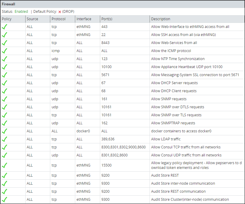
5 - Managing Firewall Settings
Protegrity internal firewall provides a way to allow or restrict inbound access from the outside to Protegrity Appliances. Using the Network Firewall tool you can manage your Firewall settings. For example, you can allow access to the management-network interface only from a specific machine while denying access to all other machines.
To improve security in the ESA, the firewall in v9.2.0.0 is upgraded to use the nftables framework instead of the iptables framework. The nftables framework helps remedy issues, including those relating to scalability and performance.
The iptables framework allows the user to configure IP packet filter rules. The iptables framework has multiple pre-defined tables and base chains, that define the treatment of the network traffic packets. With the iptables framework, you must configure every single rule. You cannot combine the rules because they have several base chains.
The nftables framework is the successor of the iptables framework. With the nftables framework, there are no pre-defined tables or chains that define the network traffic. It uses simple syntax, combines multiple rules, and one rule can contain multiple actions. You can export the data related to the rules and chains to json or xml using the nft userspace utility.
Verifying the nftables
This section provides the steps to verify the nftables.
To verify the nftables:
Log in to the CLI Manager.
Navigate to Administration > OS Console.
Enter the root password and select OK.
Run the command nft list ruleset.
The nftables rules appear.
Listing the Rules
Using the Rules List option, you can view the available firewall rules.
To view the details of the rule:
Log in to the CLI Manager.
Navigate to Networking > Network Firewall.
Enter the root password and select OK.
The following screen appears.

From the menu, select Rules List to view the list of rules.
A list of rules appear.
Select a rule from the list and click More.
The policy, protocol, source IP address, interface, port, and description appear.
Click Delete to delete a selected rule. Once confirmed, the rule is deleted.
Log in to the Web UI.
Navigate to System > Information to view the rules.
Reordering the Rules List
Using the Reorder Rules List option, you can reorder the list of rules. With buttons Move up and Move down you can move the selected rule. When done, click Apply for the changes to take effect.
The order of the specified rules are important. When reordering the firewall rules, take into account that rules which are in the beginning of the list are of the first priority. Thus, if there are conflicting rules in the list, the one which is the first in the list is applied.
Specifying the Default Policy
The default policy determines what to do on packets that do not match any existing rule. Using the Specify Default Policy option, you can set the default policy for the input chains. You can specify one of the following options:
- Accept - Let the traffic pass through.
- Drop - Remove the packet from the wire and generate no error packet.
If not specified by any rule, then the incoming packet will be dropped as the default policy. If specified by a rule, then the incoming packet will be allowed/denied or dropped depending on the policy of the rule.
Adding a New Rule
Every new rule specifies the criteria for matching packets and the action required. You can add a new rule using the Add New Rule option. This section explains how to add a firewall rule.
Adding a new rule is a multi-stage process that includes:
- Specifying an action to be taken for matching incoming traffic:
- Accept - Allow the packets.
- Drop - Remove the packet from the wire and generate no error packet.
- Reject - Remove the packet from the wire and return an error packet.
- Specifying the local service for this rule.
- Specifying the local network interface. It can be any or selected interface..
- Specifying the remote machine criteria.
- Providing a description for the rule. This is optional.
When a Firewall rule is added, it is added to the end of the Firewall list. If there is a conflicting rule in the beginning of the list, then the new rule may be ignored by the Firewall. Thus, it is recommended to move the new rule somewhere to the beginning of the Firewall rules list.
Adding a New Rule with the Predefined List of Functionality
Follow these instructions to add a new rule with the predefined list of functionality:
Select a policy for the rule, accept, drop, or reject, which will define how a package from the specific machine will be treated by the appliance Firewall.
Click Next.
Specify what will be affected by the rule. Two options are available: to specify the affected functionality list, in this case, you do not need to specify the ports since they are already predefined, or to specify the protocol and the port.
Select the local service affected by the rule. You can select one or more items to be affected by the firewall rule.
Click Next.
If you want to have a number of similar rules, then you can specify multiple items from the functionality list. Thus, for example, if you want to allow access from a certain machine to the appliance LDAP, SNMP, High Availability, SSH Management, or Web Services Management, you can specify these items in the list.
Click Manually.
In the following dialog box, select a protocol for the rule. You can select between TCP, UDP, ICMP, or any.
In the following screen, specify the port number and click Next.
In the following screen you are prompted to specify an interface. Select between ethMNG (Ethernet management interface), ethSRV0 (Ethernet security service interface), ethSRV1, or select Any.
In the following screen you are prompted to specify the remote machine. You can specify between single/IP with subnet or domain name.
When you select Single, you will be asked to specify the IP in the following screen.
When you select IP with Subnet, you will be asked to specify the IP first, and then to specify the subnet.
When you select Domain Name, you will be asked to specify the domain name.
When you have specified the remote machine, the Summary screen appears. You can enter the description of your rule if necessary.
Click Confirm to save the changes.
Click OK in the confirmation message listing the rules that will be added to the Rules list.
Disabling/Enabling the Firewall Rules
Using the Disable/Enable Firewall option, you can start your firewall. All rules that are available in the firewall rules list will be affected by the firewall when it is enabled. All new rules added to the list will be affected by the firewall. You can also restart, start, or stop the firewall using ESA Web UI.
Resetting the Firewall Settings
Using the Reset Firewall Settings option, you can delete all firewall rules. If you use this option, then the firewall default policy becomes accept and the firewall is enabled.
If you require additional security, then change the default policy and add the necessary rules immediately after you reset the firewall.
6 - Using the Management Interface Settings
Using the Management Interface Settings option, you can specify the network interface that will be used for management (ethMNG). By default, the first network interface is used for management (ethMNG). The first management Ethernet is the one that is on-board.

If you change the network interface, then you are asked to reboot the ESA for the changes to take effect.
Note: The MAC address is stored in the appliance configuration. If the machine boots or reboots and this MAC address cannot be found, then the default, which is the first network card, will be applied.
7 - Ports Allowlist
On the Proxy Authentication screen of the Web UI, you can add multiple AD servers for retrieving users. The AD servers are added as URLs that contain the IP address/domain name and the listening port number. You can restrict the ports on which the LDAP listens to by maintaining a port allowlist. This ensures that only those ports that are trusted in the organization are mentioned in the URLs.
On the CLI Manager, navigate to Networking > Ports Allowlist to set a list of trusted ports. By default, port 389 is added to the allowlist.
The following figure illustrates the Ports Allowlist screen.

This setting is applicable only to the ports entered in the Proxy Authentication screen of the Web UI.
Viewing list of allowed ports
You can view the list of ports that are specified in the allowlist.
On the CLI Manager, navigate to Networking > Ports Allowlist.
Enter the root credentials.
Select List allowed ports.
The list of allowed ports appears.
Adding ports to the allowlist
Ensure that multiple port numbers are comma-delimited and do not contain space between them.
On the CLI Manager, navigate to Networking > Ports Allowlist.
Enter the root credentials.
Select Add Ports.
Enter the required ports and select OK.
A confirmation message appears.