The Web UI is a web-based environment for managing status, policy, administration,networking, and so on. The options that you perform using the CLI manager can also be performed from the Web UI.
This is the multi-page printable view of this section. Click here to print.
Web User Interface (Web UI) Management
Describes the operations performed using the Web User Interface
- 1: Working with the Web UI
- 2: Description of ESA Web UI
- 3: Working with System
- 3.1: Working with Services
- 3.2: Viewing information, statistics, and graphs
- 3.3: Working with Trusted Appliances Cluster
- 3.4: Working with Backup and restore
- 3.4.1: Working with OS Full Backup and Restore
- 3.4.2: Backing up the data
- 3.4.3: Backing up custom files
- 3.4.4: Exporting the custom files
- 3.4.5: Importing the custom files
- 3.4.6: Working with the custom files
- 3.4.7: Restoring configurations
- 3.4.8: Viewing Export/Import logs
- 3.5: Scheduling appliance tasks
- 4: Viewing the logs
- 5: Working with Settings
- 5.1: Working with Antivirus
- 5.1.1: Customizing Antivirus Scan Options
- 5.1.2: Scheduling Antivirus Scan
- 5.1.3: Updating the Antivirus Database
- 5.1.4: Working with Antivirus Logs
- 5.2: Configuring Appliance Two Factor Authentication
- 5.2.1: Working with Automatic Per-User Shared-Secret
- 5.2.2: Working with Host-Based Shared-Secret
- 5.2.3: Working with Remote Authentication Dial-up Service (RADIUS) Authentication
- 5.2.4: Working with Shared-Secret Lifecycle
- 5.2.5: Logging in Using Appliance Two Factor Authentication
- 5.2.6: Disabling Appliance Two Factor Authentication
- 5.3: Working with Configuration Files
- 5.4: Working with File Integrity
- 5.5: Managing File Uploads
- 5.6: Configuring Date and Time
- 5.7: Configuring Email
- 5.8: Configuring Network Settings
- 5.8.1: Managing Network Interfaces
- 5.8.2: NIC Bonding
- 5.9: Configuring Web Settings
- 5.9.1: General Settings
- 5.9.2: Session Management
- 5.9.3: Shell in a box settings
- 5.9.4: SSL cipher settings
- 5.9.5: Updating a protocol from the ESA Web UI
- 5.10: Working with Secure Shell (SSH) Keys
- 6: Managing Appliance Users
- 7: Password Policy for all appliance users
1 - Working with the Web UI
Accessing the Web User Interface
The following screen displays the ESA Web UI.
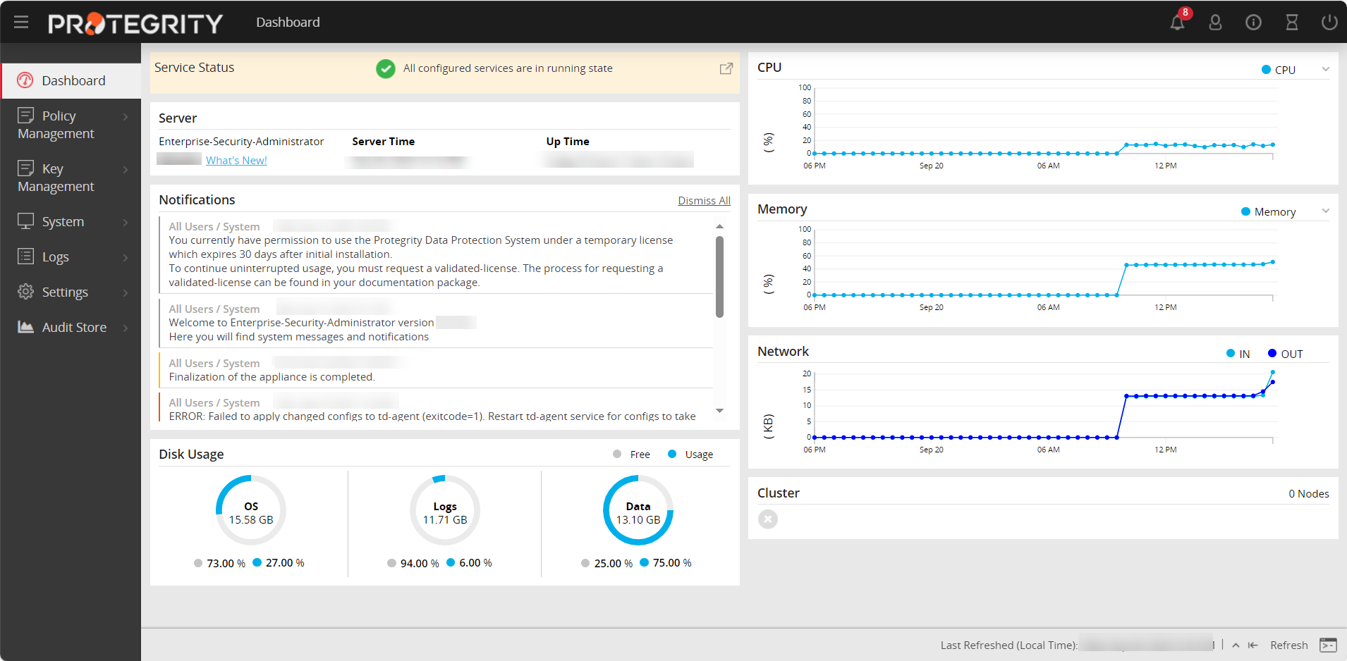
The following table describes the details of options available on the Web UI menu.
| Options | Description |
|---|---|
| Dashboard | View user notifications, disk usage, alerts, server details, memory / CPU / network utilization, and cluster status |
| Policy Management | Manage creating and deploying policies. For more information about keys, refer Policy Management. |
| Key Management | Manage master data. For more information about keys, refer to the Key Management. |
| System | Configure Trusted Appliances Cluster, set up backup and restore, view system statistics, graphs, information, and manage services. |
| Logs | View logs that are generated for web services. |
| Settings | Configure network settings, set up certificates, manage users, roles, and licenses. |
| Audit Store | Manage the repository for all audit data and logs. For more information about the Audit Store, refer Audit Store. View dashboards that display information using graphs and charts for a quick understanding of the protect, unprotect, and reportect transactions performed. For more information about dashboards, refer Dashboards. |
The following figure describes the icons that are visible on the ESA Web UI.
| Icon | Description |
|---|---|
 | Download support logs, view product documentation, and view the version information about the ESA and its components. |
 | Extend session timeout |
 | Notifications and alerts |
 | Edit profile or sign out of the profile |
 | Power off or restart the system |
Logging into the ESA Web UI
Log in to the ESA Web User Interface (Web UI) to manage the appliance settings and monitor your appliance.
- When you login through the CLI or the Web UI for the first time, with the password policy enabled, the Update Password screen appears. It is recommended that you change the password since the administrator sets the initial password.
- It is recommended to configure your browser settings such that passwords are not saved. If you save the password, then on your next login you would start the session as a previously logged-in user.
The following screen displays the login screen of the Web UI.
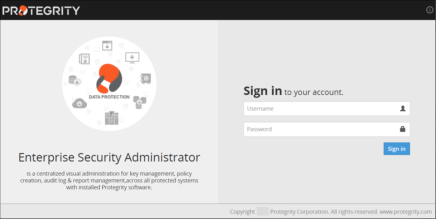
To log into the ESA Web UI:
- From your web browser, type the Management IP address for your ESA using HTTPS protocol, for example, https://10.0.0.185/.The Web Interface splash screen appears.
- Enter your user credentials.If the credentials are approved, then the ESA Dashboard appears.
Viewing user notifications
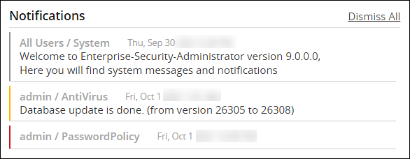
There is a message at the top of the screen with the number of notifications that appear on this page and other web pages. If you click on the notification, then it is directed to the Services and Status screen.
Alternatively, you can store the messages in the Audit Store and use Discover to view the detailed logs.
You can delete the messages after reading them.
The messages that are older than a year are automatically deleted from the User Notification list, but retained in the logs.
On the User Notifications area of the ESA, the notifications and events occurring on the appliances communicating with it are also visible.
For the notifications to appear on the ESA, ensure that same set of client key pair are present on the ESA and the appliances that communicate with the ESA.For more information about certificates, refer Certificate Management.
Scheduled tasks generate some of these messages. To view a list of scheduled tasks that generate these messages, navigate to System > Task Scheduler.
Logging out of the ESA Web UI
There are two ways to log off the ESA Web UI.
- Log off as a user, while the ESA continues to run.
- Restart or shut down the ESA.
In case of cloud platforms, such as, Azure, AWS or GCP, the instances run the appliance.
To log out as a user:
Click the second icon that appears on the right of the ESA Toolbar.
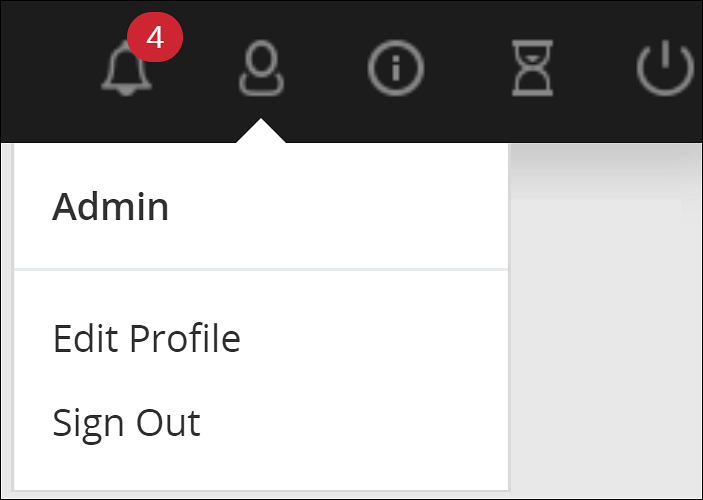
Click Sign Out.
The login screen appears.
Shutting down the ESA
The Reboot option shuts down the ESA and restarts it again. Users will need to login again when the authentication screen appears.
With cloud platforms such as Azure, AWS, or GCP, the instances run the appliance. Powering off the instance from the cloud console may not shut down the ESA gracefully. It is recommended to power off from the CLI Manager or Web UI.
To shut down the ESA:
Click the last icon from ESA Toolbar.
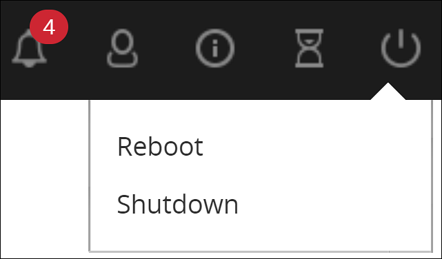
Click Shutdown.
Enter your password to confirm.
Provide the reason for the shut down and click OK.
The ESA server shuts down. The Web UI screen may continue to display on the window; however, the Web UI does not work.
2 - Description of ESA Web UI
Describes the Web User Interface
The ESA Web UI appears upon successful login. This page shows the Host to which you are attached, IP address, and the current user logged on.
This operation might require a few minutes to begin.
The different menu options are given in the following table.
| Option | Using this navigation menu you can | Applicable to |
|---|---|---|
| Dashboard | A view-only window, which provides status at a glance – service, server, notifications, disk usage, and graphical representation of CPU, memory, and network usage. | All |
| Policy Management | Used to create data stores, data elements, masks, roles, keys, and deploy a policy. | ESA |
| Key Management | Used to view information, rotate, or change the key states of the Master Key, Repository Key, and Data Store Keys. View information for the active Key Store or switch the Key Store. | ESA |
| System |
| All |
| Logs | Used to view logs for separate tasks such as web services engine, policy management, DFSFP, and Appliance. | ESA |
| Settings |
| All |
| Audit Store | A repository for all audit data and logs. It is used to initialize analytics, view and analyze Insight dashboards, and manage cluster. | ESA |
| Cloud Gateway | Used to create certificate, tunnel, service, Rules for traffic flow management, add DSG nodes to cluster, monitor cluster health, view logs. | DSG |
The following graphic illustrates the different panes in the ESA Web UI.
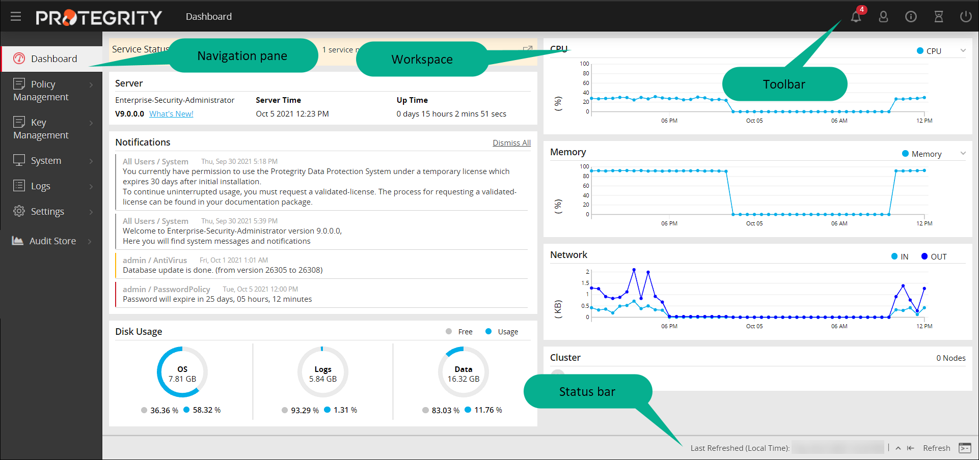
| Component | Description |
|---|---|
| Navigation Pane | The number of options in the navigation menu depends on the installed ESA. The functionality is also restricted based on the user permissions. You could have read-write or read-only permissions for certain options. Using the different options, you can create a policy, add a user, run a few security checks such as file integrity or scan for virus, review or change the network settings, among others. |
| Workspace | This window on the right includes either displayed information or fields where information needs to be added. When an option is selected, the resulting window appears. |
| Status Bar | The bar at the bottom displays the last refresh activity time. Also, if you click the rectangle a separate ESA CLI screen opens. All these options are available in the CLI screen as well. |
| Toolbar | This bar at the top displays the name of the currently open window on the left and icons on the right. |
The details of the icons in the toolbar is as follows:
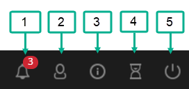
| Component | Icon Name | Description |
|---|---|---|
| 1 | Notification | The number is the total number of unopened messages for you. |
| 2 | User | Change your password or log out as a user. ESA continues to run. |
| 3 | Help | Download the file(s) that are required by Protegrity Support for troubleshooting, view the product documentation, and view the version information about the ESA and its components. |
| 4 | Session | Extend the session without timing out. You have to enter your credentials again to login. |
| 5 | Power Option | Reboot or shut down the ESA, after ensuring that the ESA is not being used. |
Support
The Help option on the toolbar, allows you to download information about the status of the ESA and other services that is sometimes required by Protegrity Services to troubleshoot.
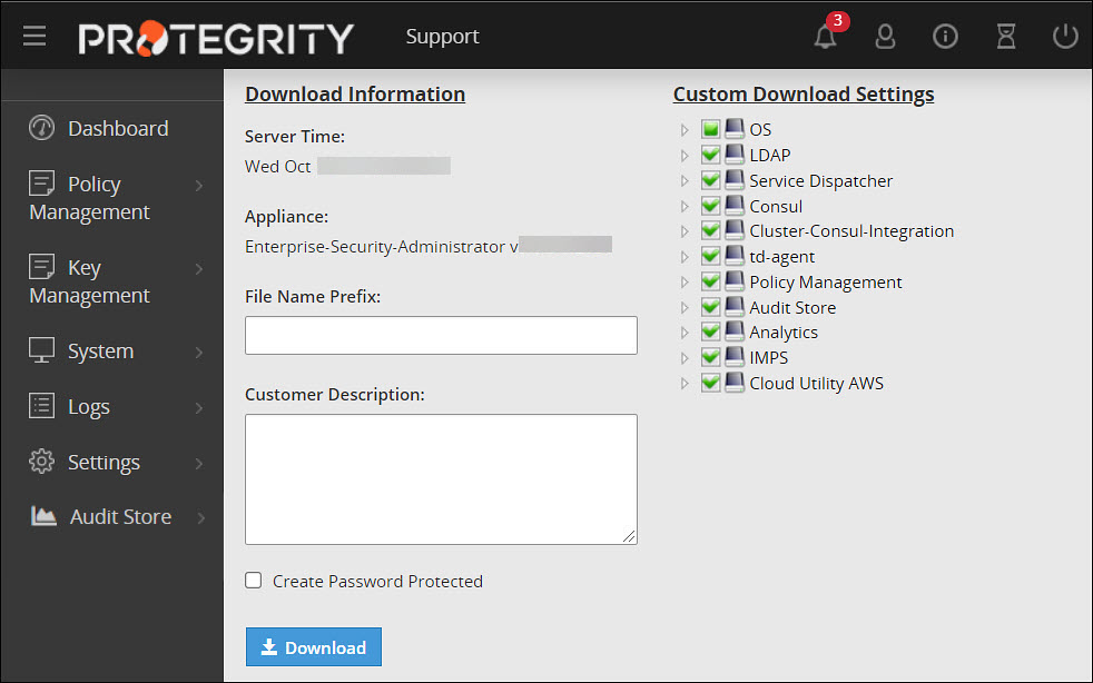
Check the boxes that you require and optionally provide a prefix to the automatically generated file name. You may optionally add a description and protect the resulting zip file and all the xml files inside with a password.
Viewing Version of the Installed Components of the ESA
The  > About option on the toolbar allows you to view the version information about the ESA and its components.
The following figure shows the version information of the installed components of the ESA.
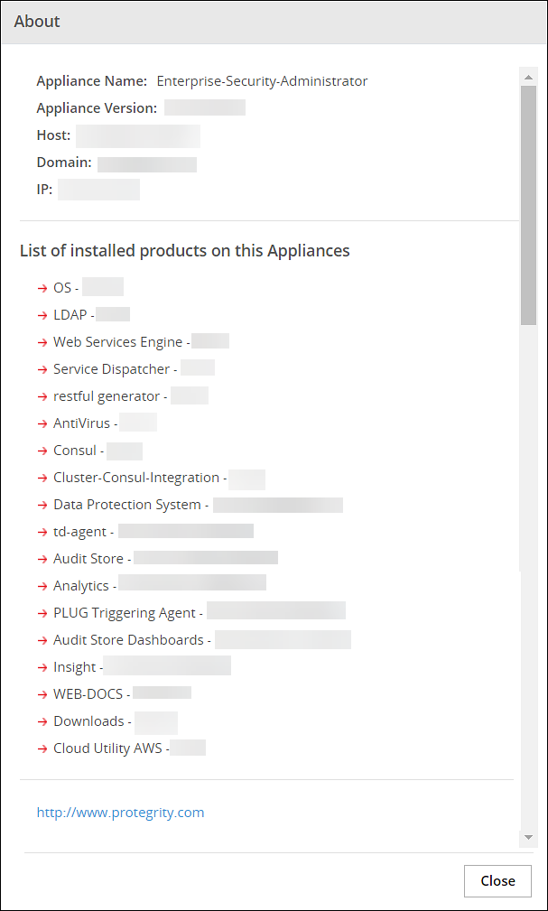
For example, you can view the version of the Data Protection System (DPS) that is being used.
Extending Timeout from ESA
The following icons are available on the top right corner of the ESA Web UI page.

The hourglass icon enables you to extend the working time for the ESA. To extend the timeout for the ESA Web UI, click on the hourglass icon.
A message appears mentioning Session timeout extended successfully.
3 - Working with System
Describes the system information page
The System Information navigation folder includes all information about the appliance listed below.
- Services and their statuses
- The hardware and software information
- Performance statistics
- Graphs
- Real-time graphs
- Appliance logs
System option available on the left pane provides the following options:
| System Options | Description |
|---|---|
| Services | View and manage OS, logging and reporting, policy management and other miscellaneous services. |
| Information | View the health of the system. |
| Trusted Appliances Cluster | View the status of trusted appliances clusters and saved files. |
| System Statistics | View the performance of the hardware and networks. |
| Backup and Restore | Take backups of files and restore these, as well as take backups of full OS and log files. |
| Task Scheduler | Schedule tasks to run in the background such as anti-virus scans and password policy checks, among others. |
| Graphs | View how the system is running in a graphical form. |
3.1 - Working with Services
Describes the services section on the Web UI
You can manually start, restart, and stop services in the appliance. You can act upon all services at once, or select specific ones.
In the System > Services page, the tabs list the available services and their statuses. The Information tab appears with the system information like the hardware information, system properties, system status, and open ports.
Although the services can be started or stopped from the Web UI, the start/stop/restart action is restricted for some services. These services can be operated from the OS Console.Run the following command to start/stop/restart a service.
/etc/init.d/<service_name> stop/start/restart
For example, to start the docker service, run the following command.
/etc/init.d/docker start
If you stop the Service Dispatcher service from the Web UI, you might not be able to access ESA from the Web browser. Hence, it recommended to stop the Service Dispatcher service from the CLI Manager only.
Web Interface Auto-Refresh Mode
You can set the auto-refresh mode to refresh the necessary information according to a set time interval. The Auto-Refresh is available in the status bar that show the dynamically changing status information, such as status and logs. Thus, for example, an Auto Refresh pane is available in System > Services, at the bottom of the page.
The Auto-Refresh pane is not shown by default. You should click the Auto-Refresh button to view the pane.
To modify the auto-refresh mode, from the Appliance Web Interface, select the necessary value in the Auto-Refresh drop-down list. The refresh is applied in accordance with the set time.
3.2 - Viewing information, statistics, and graphs
Describes the detailed information, statistics, and graphs
Viewing System Information
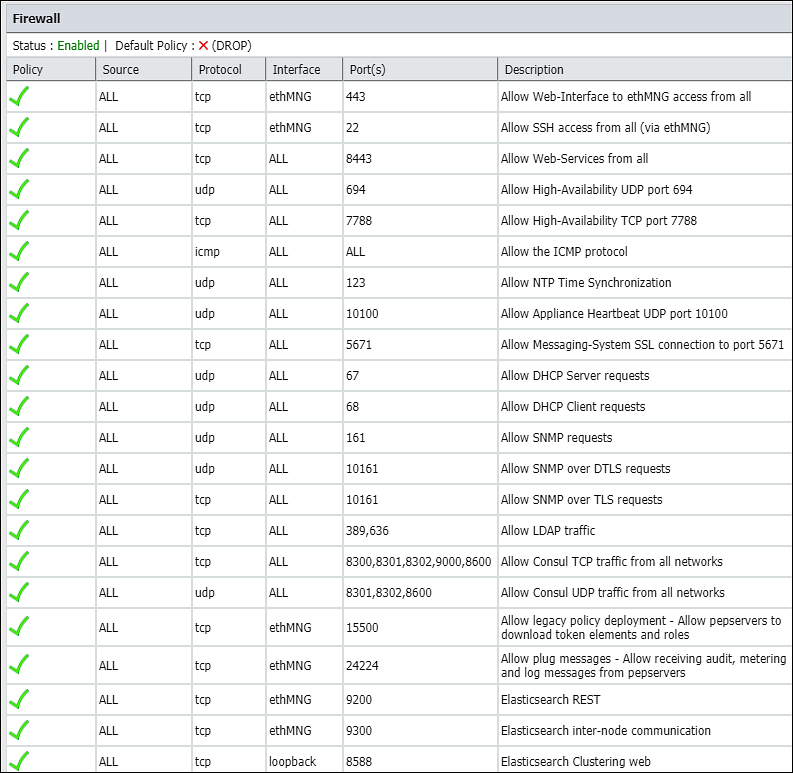
All hardware information, system properties, system statuses, open ports and firewall rules are listed in the Information tab.
The information is organized into sections called Hardware, System Properties, System Status, Open Ports, and Firewall.
Hardware section includes information on system, chipset, processors, and amount of total RAM.
System Properties section appears with information on current Appliance, logging server, and directory server.
System Status section lists such properties as data and time, boot time, up time, number of logged in users, and average load.
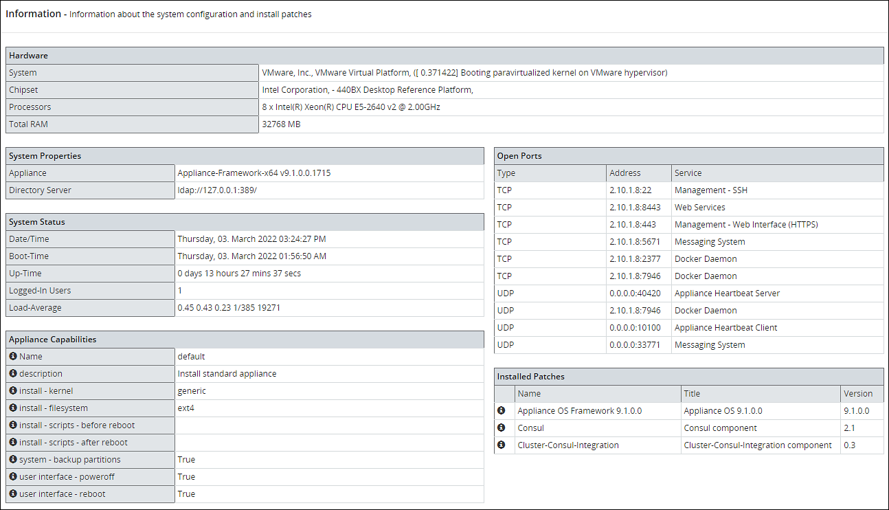
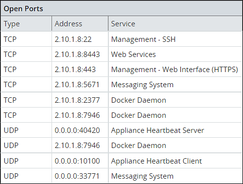
Open Ports section lists types, addresses, and names of services that are running.
Firewall section in System > Information lists all firewall rules, firewall status (enabled/disabled), and the default policy (drop/accept) which determines what to do on packets that do not match any existing rule.
Viewing System Statistics
Using System > System Statistics, you can view performance statistics to assess system usage and efficiency. The Performance page refreshes itself every few seconds and shows the statistics in real time.
The Performance page shows system information:
- Hardware - System, chipset, processors, total RAM
- System Status - Date/time, boot time, up-time, users connected, load average
- Networking - Interface, address, bytes sent/received, packets sent/received
- Partitions - Partition name and size, used and avail
- Kernel - Idle time, kernel time, I/O time, user time
- Memory - Memory total, swap cached, and inactive, among others
You can customize the page refresh rate, so that you are viewing the latest information at any time.
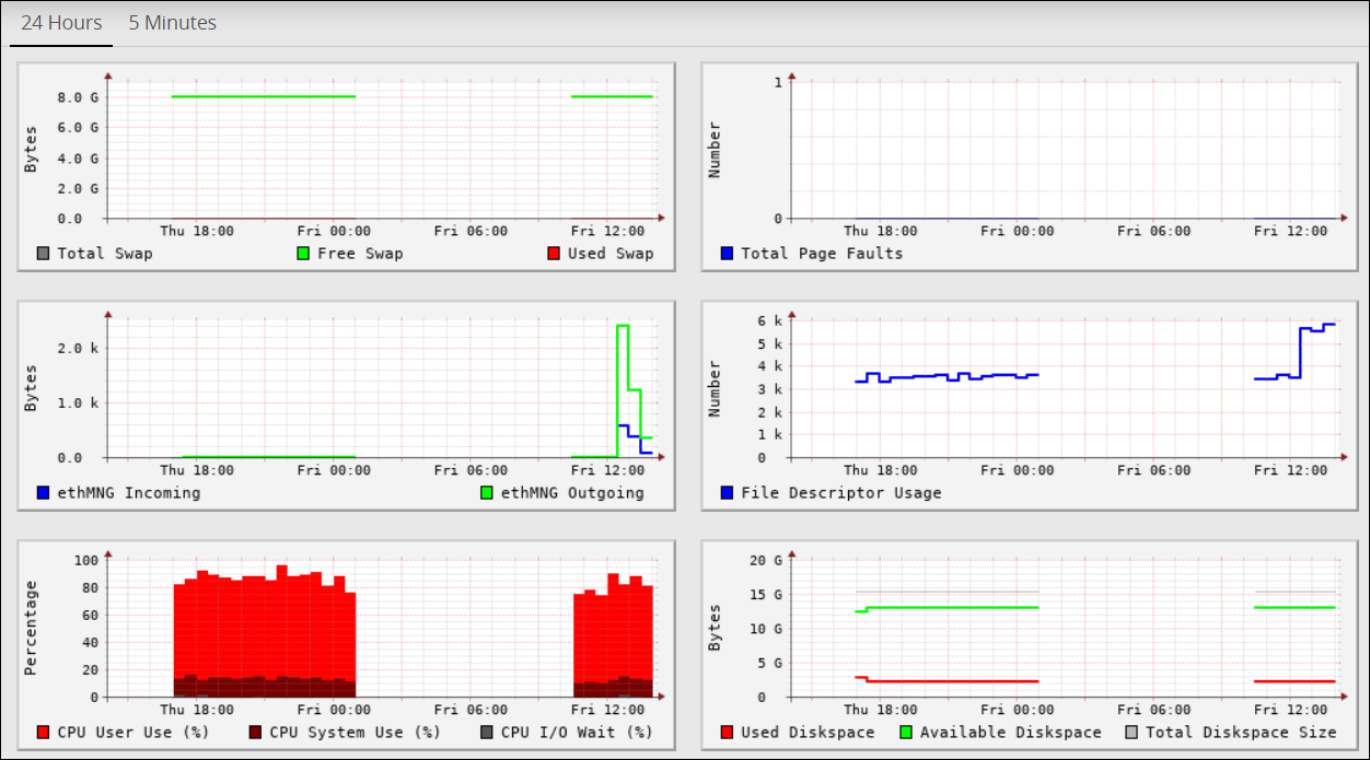
Viewing Performance Graphs
Using System > Graphs, you can view performance graphs and real-time graphs in addition to statistics. In the Performance tab you can view a graphical representation of performance statistics from the past 5 minutes or past 24 hours for these items:
- CPU application use - % CPU I/O wait, CPU system use
- Total RAM - Free RAM, used RAM
- Total Swap - Free Swap, used Swap
- Free RAM
- Used RAM
- System CPU usage
- Application CPU use, %
- Log space used - Log space available, log space total
- Application data used - Application data available space, application data total size
- Total page faults
- File descriptor usage
- ethMNG incoming/ethMNG outgoing
- ethSRV0 incoming/ethSRV0 outgoing
- ethSRV1 incoming/ethSRV1 outgoing
In the Realtime Graphs tab you can monitor current state of performance statistics for these items:
- CPU usage
- Memory Status - free and used RAM
The following figure illustrates the Realtime Graphs tab.
3.3 - Working with Trusted Appliances Cluster
Overview of the services for Trusted Appliances Cluster
The Clustering menu becomes available in the appliance Web Interface, System > Trusted Appliance Cluster. The status of the cluster is by default updated every minute, and it can be configured using Cluster Service Interval, available in the CLI Manager.
Status tab appears with the information on nodes which are in the cluster. In the Filter drop-down combo box, you can filter the nodes by the name, address and label.
In the Display drop-down combo box, you can select to display node summary, top 10 CPU consumers, top 10 Memory consumers, free disk report, TCP/UDP network information, system information, and display ALL.
Saved Files tab appears with the files that were saved in the CLI Manager. These files show the status of the appliance cluster node or the result of the command run on the cluster.
3.4 - Working with Backup and restore
Describes the procedure to back up and restore
The backup process copies or archives data. The restore process ensures that the original data is restored if data corruption occurs.
You can back up and restore configurations and the operating system from the Backup/Restore page. It is recommended to have a backup of all system configurations.
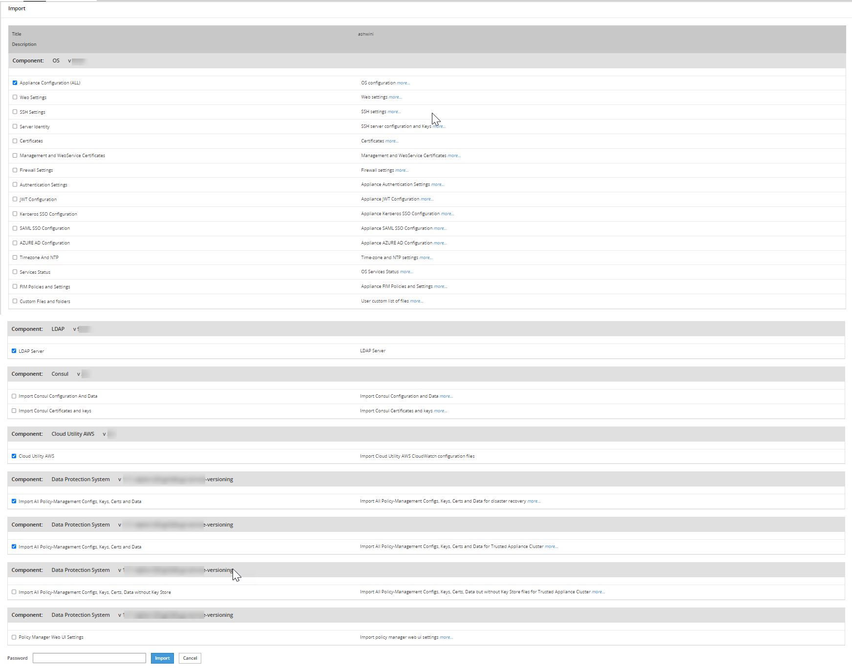
The Backup/Restore page includes Export, Import, OS Full, and Log Files tabs, which you can use to create configuration backups and restore them later.
Using Export, you can also export a configuration to a trusted appliances cluster, and schedule periodic replication of the configuration on all nodes that are in the trusted appliances cluster. Using export this way, you can periodically update the configuration on all, or just necessary nodes of the cluster.
Using Import, you can restore the created backups of the product configurations and appliance OS core configuration.
Using Full OS Backup, you can create backup of the entire appliance OS.
The Full OS Backup/Restore features of the Protegrity appliances is not available on the cloud platform.
3.4.1 - Working with OS Full Backup and Restore
Describes the procedure to back up and restore the entire OS
It is recommended to perform the full OS back up before any important system changes, such as appliance upgrade or creating a cluster, among others.
This option is available only for the on-premise deployments. It is not available for virtual machines created using an OVA template and cloud-based virtual machines.
Backing up the appliance OS
The backup process may take several minutes to complete.
Perform the following steps to back up the appliance OS.
Log in to the Appliance Web UI.
Proceed to System > Backup > Restore.
Navigate to the O.S Full tab and click Backup.
A confirmation message appears.
Press ENTER.
The Backup Center screen appears and the OS backup process is initiated.
Navigate to Appliance Dashboard.A notification O.S Backup has been initiated appears. After the backup is complete, a notification O.S Backup has been completed appears.
Restoring the appliance OS
Use caution when restoring the appliance OS. Consider a scenario where it is necessary to restore a full OS backup that includes the external Key Store data. If the external Key Store is not working, then the HubController service does not start after the restore process.
Perform the following steps to restore the appliance OS.
- Login to the Appliance Web UI.
- Proceed to System > Backup & Restore.
- Navigate to the O.S Full tab and click Restore.A message that the restore process is initiated appears.
- Select OK.The restore process starts and the system restarts after the process is completed.
- Log in to the appliance and navigate to Appliance Dashboard.A notification O.S Restore has been completed appears.
3.4.2 - Backing up the data
Describes the procedure to back up data using the export feature
Using the Export tab, you can create backups of the product configurations and/or appliance OS core configuration.
Before you begin
Starting from the Big Data Protector 7.2.0 release, the HDFS File Protector (HDFSFP) is deprecated. The HDFSFP-related sections are retained to ensure coverage for using an older version of Big Data Protector with the ESA 7.2.0.
If you plan to use ESAs in a Trusted Appliances Cluster, and you are using HDFSFP with the DFSFP patch installed on the ESA, then ensure that you clear the DFSFP_Export check box when exporting the configurations from the ESA, which will be designated as the Master ESA.
In addition, for the Slave ESAs, ensure that the HDFSFP datastore is not defined and the HDFSFP service is not added.
The HDFSFP data from the Master ESA should be backed up to a file and moved to a backup repository outside the ESA. This will help in retaining the data related to HDFSFP, in cases of any failures.
Backing up configuration to local file
Perform the following steps to backup the configuration to local file.
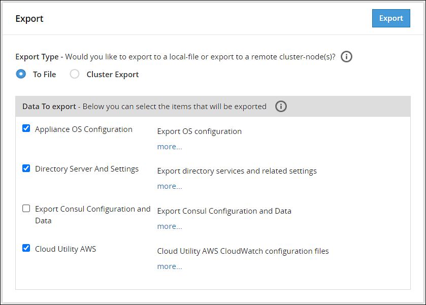
- Navigate to System > Backup & Restore > Export.
- In the Export Type area, select To File radio button.
- In the Data To export area, select the items to be exported.Click more.. for the description of every item.
- Click Export.The Output File screen appears.
- Enter information in the following fields:
- Output File: Name of the file.
If you want to replace an existing file on the system with this file, click the Overwrite existing file check box. - Password: Password for the file.
- Export Description: Information about the file.
- Output File: Name of the file.
- Click Confirm.A message
Export operation has been completed successfullyappears. The created configuration is saved to your system.
Exporting Configuration to Cluster
You can export your appliance configuration to the trusted appliances cluster, which your appliance belongs to. The procedure of creating the backup is almost the same as exporting to a file.
You need to define what configurations to export, and which nodes in the cluster receive the configuration. You do not need to import the files as is required when backing up the selected configuration. The configuration will be automatically replicated on the selected nodes when you export the configuration to the cluster.
When you are exporting data from one ESA to other, ensure that you run separate tasks to export the LDAP settings first and then the OS settings.
When exporting configurations to cluster nodes (from primary ESA to secondary ESAs), ensure to not select the following options in the Data To Export section:
- SSH Settings
- Certificates
- Management and WebService Certificates
- Import All Policy-Management Configs, Keys, Certs, Data but without Key Store files for Trusted Appliance Cluster
Important: Scheduled tasks are not replicated as part of cluster export.
For information about copying Insight certificates across systems, refer to Rotating Insight certificates.
Perform the following steps to export a configuration to a trusted appliances cluster.
Log in to the primary ESA using the admin credentials.
Navigate to System > Backup & Restore > Export.
In the Export Type area, select the To Cluster radio button.
In the Data to Export, select the items that you want to export from your machine and import to the cluster nodes.
Click Next.
In the Source Cluster Nodes, select the nodes that will run this task.
Specify the nodes by label or select individual nodes.
Click Next.
In the Target Cluster Nodes, select the nodes where the configuration needs to be exported. Specify them by label or select individual nodes. Select to show command line, if necessary.
Click Review.
The New Task screen appears.
Enter the required information in the following sections.
- Basic Properties
- Frequencies
- Restriction
- Logging
Click Save.
A dialog box to enter the root password appears.
Enter the root password and click OK.
The scheduled task is created.
Navigate to System > Task Scheduler.
Select the created task and click Run Now! to run the scheduled task immediately.
A confirmation dialog box appears. Click Ok.
The configurations are exported to the selected cluster nodes.
3.4.3 - Backing up custom files
Describes the procedure to back up custom files using the export feature
In the ESA, you can export or import the files that cannot be exported using the cluster export task. The custom set of files include configuration files, library files, directories containing files, and any other files. On the ESA Web UI, navigate to Settings > System > Files to view the customer.custom file. That file contains the list of files to include for export and import.
The following figure displays a sample snippet of the customer.custom file.
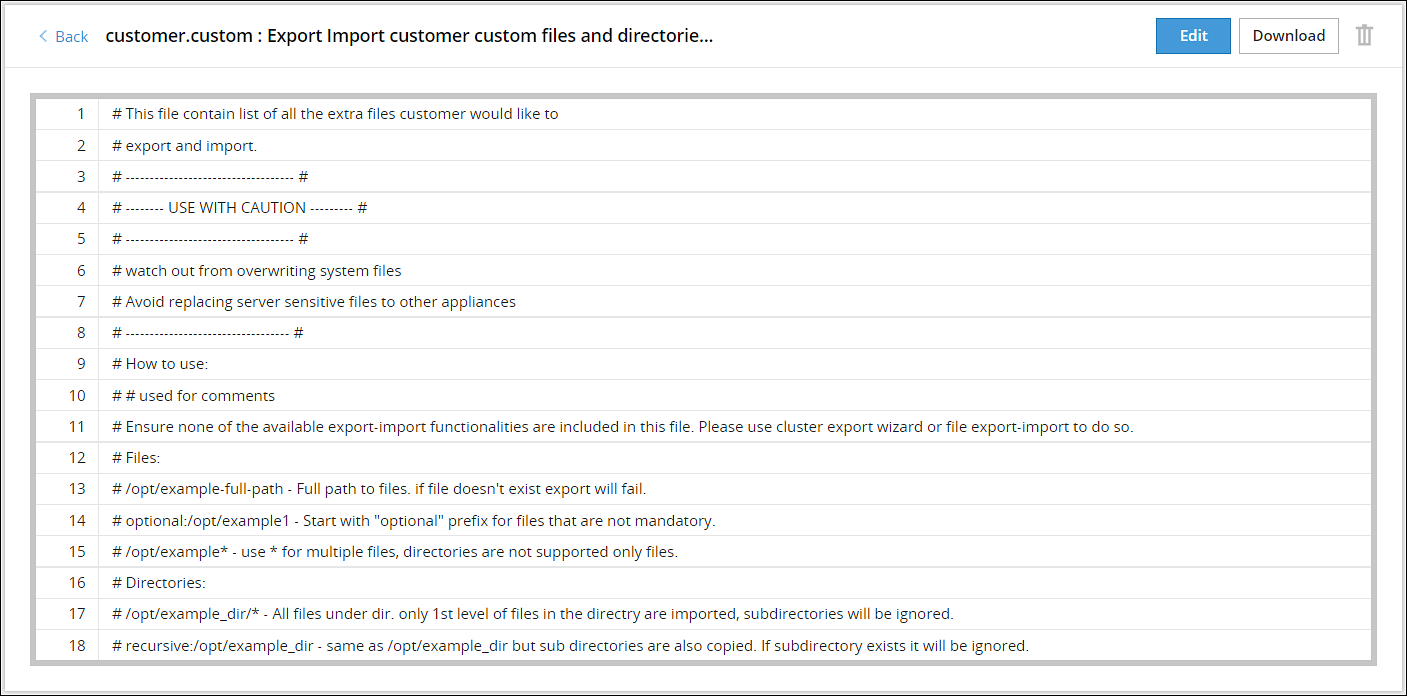
If you include a file, then you must specify the full path of the file. The following snippet explains the format for exporting a file.
/<directory path>/<filename>.<extension>
For example, to export the abc.txt file that is present in the test directory, you must add the following line in the customer.custom file.
/test/abc.txt
If the file does not exist, then an error message appears and the import export process terminates. In this case, you can add the prefix optional to the file path in the customer.custom file. This ensures that if the file does not exist, then the import export process continues without terminating abruptly.
If the file exists and the prefix optional is added, then the file is exported to the other node.For example, if the file 123.txt is present in the test directory, then it is exported to the other node. If the file does not exist, then the export of this file is skipped and the other files are exported.optional:/abc/test/123.txt
For more information about exporting files, refer Editing the customer.custom File.
If you include a directory, then you must specify the full path for the directory. All the files present within the directory are exported. The following snippet explains the format for exporting all the files in a directory.
/<directory path>/*
For example, to export a directory test_dir that is present in the /opt directory, add the following line in the customer.custom file.
/opt/test_dir/*
You can also include all the files present under the subdirectories for export. If you prefix the directory path with the value recursive, then all the files within the subdirectories are also exported.
For example, to export all the subdirectories present in the test_dir directory, add the following line in the customer.custom file.
recursive:/opt/test_dir/
For more information about exporting directories, refer to the section Editing the customer.custom File to Include Directories.
You must export the custom files before importing them to a file or on the other nodes on a cluster.
3.4.4 - Exporting the custom files
Describes the procedure to export the customer.custom file to a local file or to a cluster
Perform the following steps to export the customer.custom file to a local file or to a cluster.
Exporting the customer.custom file to a local file
- Navigate to System > Backup & Restore > Export.
- In the Export Type area, select To File.
- In the Data To Export area, select Appliance OS Configuration.
- Click Export.The Output file screen appears.
- Enter the name of the file in the Export Name text box.
- Enter the required password in the Password text box.
- Click Confirm.The message Export operation has been completed successfully appears.
- Click the Done button.The file is exported and is stored in the
/products/exportsdirectory.
- On the CLI Manager, navigate to Administration > Backup/Restore Center > Export data/configurations to a local file.
- Select Appliance OS Configuration and select OK.A screen to enter the export information appears.
- Enter the required name of the file in the Export Name text box.
- Enter the required password in the Password and Confirm text boxes.
- Select OK.
- Select Done after the export operation completes.
Exporting the customer.custom file on a cluster
On the Web UI, navigate to System > Backup & Restore > Export.
In the Export Type area, select Cluster Export option.
If the configurations must be exported to a different ESA, then clear the Certificates check box. If you import the ESA Management and WebService Certificates from a different node in the cluster, then rotate the Insight certificates after the import is complete. For rotating the Insight certificates, use the steps from Rotating Insight certificates.
Click Start Wizard.
Select User custom list of files in the Data To Import tab.
Click Next.
Select the required options in the Source Cluster Nodes tab and click Next.
Select the required options in the Target Cluster Nodes tab and click Review.
Enter the required data in the Basic Properties, Frequency, Logging, and Restriction areas.For more information about the task details, refer Schedule Appliance Tasks. The message Export operation has been completed successfully appears.
Click Save.A File saved message appears.
- On the CLI Manager, navigate to Administration > Backup/Restore Center > Export data/configurations to remote appliance(s).
- Select the required file or configuration to export and select OK.
- Enter the required password for the file or configuration.
- Select Custom Files and folders and select OK.
- Enter the required credentials for the target appliance on the Target Appliance(s) screen.
- Select OK.The custom files and configurations are exported to the target node.
- Click Save.
3.4.5 - Importing the custom files
Describes the procedure to import the customer.custom file to a local file or to a cluster
Perform the following steps to import the customer.custom file to a local file.
Importing the customer.custom file to a local file
- On the Web UI, navigate to System > Backup & Restore > Import.
- From the dropdown menu, select the exported file.
- Click Import.
- On the following screen, select Custom Files and folders.
- Enter the password for the file in the Password text box and click Import.
The message File
has been imported successfully appears. - Click Done.
- On the CLI Manager, navigate to Administration > Backup/Restore Center > Import configurations from a local file.The Select an item to import screen appears.
- Select the required file or configuration to export and select OK.The contents of the file appear.
- Select OK.
- Enter the required password on the following screen and select OK.
- Select the required components.
Warning: Ensure to select each component individually.
- Select OK.The file import process starts.
- Select Done after the import process completes.
3.4.6 - Working with the custom files
Describes the procedure to edit the customer.custom file or directory
Editing the customer.custom file
Administration privileges are required for editing the customer.custom file.
This section describes the various options that are applicable when you export a file.
Consider the following scenarios for exporting a file:
- Include a file abc.txt present in the /opt/test directory.
- Include all the file extensions that start with abc in the /opt/test/check directory.
- Include multiple files using regular expressions.
To edit the customer.custom file from the Web UI:
- On the Web UI, navigate to Settings > System > Files.
- Click Edit beside the customer.custom file.
- Configure the following settings to export the file.
#To include the abc.txt file /opt/test/abc.text #If the file does not exist, skip the export of the file optional:/opt/test/pqr.txt #To include all text files /opt/test/*.txt #To include all the files extensions for file abc present in the /opt/test/check directory /opt/test/check/abc.* #To include files file1.txt, file2.txt, file3.txt, file4.txt, and file5.txt /opt/test/file[1-5].txt - Click Save.
It is recommended to use the Cluster export task to export Appliance Configuration settings, SSH settings, Firewall settings, LDAP settings, and HA settings. Do not import Insight certificates using Certificates, rotate the Insight certificates using the steps from Rotating Insight certificates.If the files exist at the target location, then they are overwritten.
Editing the customer.custom File to Include Directories
This section describes the various options that are applicable when you export a file.
Consider the following scenarios for exporting files in a directory:
- Export files is the directory abc_dir present in the /opt/test directory
- Export all the files present in subdirectories under the abc_dir directory
Ensure that the files mentioned in the customer.custom file are not specified in the exclude file.For more information about the exclude file, refer to the section Editing the Exclude File.
To edit the customer.custom file from the Web UI:
On the Web UI, navigate to Settings > System > Files.
Click Edit beside to the customer.custom file.The following is a snippet listing the sample settings for exporting a directory.
#To include all the files present in the abc directory
/opt/test/abc_dir/*
#To include all the files in the subdirectories present in the abc_dir directory
recursive:/opt/test/abc_dir
If you have a Key Store configured with ESA, then you can export the Key Store libraries and files using the customer.custom file. The following is a sample snippet listing the settings for exporting a Key Store directory.
#To include all the files present in the Safeguard directory
/opt/safeguard/*
#To include all the files present in the Safenet directory
/usr/safenet/*
The following is a sample snippet listing the settings for exporting the self-signed certificates.
#To include all the files present in the Certificates directory
/etc/ksa/certificates
Click Save.
Editing the customer.custom File to include files
The library files and other settings that are not exported using the cluster export task can be addressed using the customer.custom file.
Ensure that the files mentioned in the customer.custom file are not specified in the exclude file.For more information about the exclude file, refer to the section Editing the Exclude File.
To edit the customer.custom file from the Web UI:
On the Web UI, navigate to Settings > System > Files.
Click Edit beside to the customer.custom file.If you have a Key Store configured with ESA, then you can export the Key Store libraries and files using the customer.custom file. The following is a sample snippet listing the settings for exporting a Key Store directory.
#To include all the files present in the Safeguard directory
/opt/safeguard/*
#To include all the files present in the Safenet directory
/usr/safenet/*
The following is a sample snippet listing the settings for exporting the self-signed certificates.
#To include all the files present in the Certificates directory
/etc/ksa/certificates
Click Save.
Editing the exclude files
The exclude file contains the list of system files and directories that you don’t want to export. You can access the exclude file from the CLI Manager only. The exclude file is present in the /opt/ExportImport/filelist directory.
- A user which has root privileges is required to edit the exclude file, as it lists the system directories that you cannot import.
- If a file or directory is present in both the exclude file and the customer.custom file, then the file or directory is not exported.
The following directories are in the exclude file:
- /etc
- /usr
- /sys
- /proc
- /dev
- /run
- /srv
- /boot
- /mnt
- /OS_bak
- /opt_bak
The list of files mentioned in the exclude file affect only the customer.custom file and not the standard cluster export tasks.
If you want to export or import files, then ensure that these files are not listed in the exclude file.
To edit the exclude file:
- On the CLI Manager, navigate to Administration > OS Console.
- Navigate to the
/opt/ExportImport/filelist/directory. - Edit the exclude file using an editor.
- Perform the required changes.
- Save the changes.
3.4.7 - Restoring configurations
Describes the procedure to restore the backup configurations
Using the Import tab, you can restore the created backups of the product configurations and appliance OS core configuration. Using the Import tab, you also can upload a configuration file saved on your local machine to the appliance. You can also download a configuration file from the appliance and save it to your local machine.
Using the Import tab, you also can:
- Upload a configuration file saved on your local machine to the appliance.
- Download a configuration file from the appliance and save it to your local machine.
Before importing
Before importing the configuration files, ensure that the required products are installed in the appliance. For example, if you are importing files related to Consul Configuration and Data, ensure that the Consul product is installed in the appliance.
When you import files or configurations on an appliance from another appliance, different settings such as, firewall, SSH, or OS are imported. During this import, the settings on the target appliance might change. This might cause a product or component on the target appliance to stop functioning. Thus, after an import of the file or settings is completed, ensure that the settings, such as, ports, SSH, and firewall on the target machine are compatible with the latest features and components.For example, new features, such as, Consul are added to v7.1 MR2. When you import the settings from the previous versions, the settings in v7.1 MR2, such as, firewall or ports are overridden. So, you must ensure that the rules are added for the functioning of the new features.
When you import files or configurations, ensure that each component is selected individually.
Restoring configuration from backup
To restore a configuration from backup:
Navigate to the System > Backup & Restore.
Navigate to the Import tab, select a saved configuration from the list and click Import.
Choose specific components from the exported configuration if you do not want to restore the whole package.
If the configurations must be imported on a different ESA, then clear the Certificates check box. If you import the ESA Management and WebService Certificates from a different node in the cluster, then rotate the Insight certificates after the import is complete. For rotating the Insight certificates, use the steps from Rotating Insight certificates.
In the Password field, enter the password for the exported file and click Import.
3.4.8 - Viewing Export/Import logs
Procedure to view the saved logs
When you export or import files using the Web UI, the operation log is saved automatically. These log files are displayed in Log Files tab. You can view, delete, or download the log files.
When you export or import files using the CLI Manager, the details of the files are logged.
3.5 - Scheduling appliance tasks
Describes the scheduled tasks
Navigating to System > Task Scheduler you can schedule appliance tasks to run automatically. You can create or manage tasks from the ESA Web UI.
3.5.1 - Viewing the scheduler page
Describes the scheduler page
The following figure illustrates the default scheduled tasks that are available after you install the ESA.

The Scheduler page displays the list of available tasks.
To edit a task, click Edit. Click Save and then click Apply and enter the root password after performing the required changes.
To delete a task, select the required task and click Remove. Then, click Apply and enter the root password to remove the task.
On the ESA Web UI, navigate to Audit Store > Dashboard > Discover screen to view the logs of a scheduled task.
For creating a scheduled task, the following parameters are required.
- Basic properties
- Customizing frequency
- Execution
- Restrictions
- Logging
The following tasks must be enabled on any one ESA in the Audit Store cluster. Enabling the tasks on multiple nodes will result in a loss of data. If these scheduler task jobs are enabled on an ESA that was removed, then enable these tasks on another ESA in the Audit Store cluster.
- Update Policy Status Dashboard
- Update Protector Status Dashboard
Basic properties
In the Basic Properties section, you must specify the basic and mandatory attributes of the new task. The following table lists the basic attributes that you need to specify.
| Attribute | Description |
|---|---|
| Name | A unique numeric identifier must be assigned. |
| Description | The task displayed name, which should also be unique. |
| Frequency | You can specify the frequency of the task: |
Customizing frequency
In the Frequency section of the new scheduled task, you can customize the frequency of the task execution. The following table lists the frequency parameters which you can additionally define.
| Attribute | Description | Notes |
|---|---|---|
| Minutes | Defines the minutes when the task will be executed: | Every minute is the default. You can select several options, or clear the selection. For example, you can select to execute the task on the first, second, and 9th minute of the hour. |
| Days | Defines the day of the month when the task will be executed | Every day is the default. You can select several options, or clear the selection. |
| Days of the week | Defines the day of the week when the task will be executed: | Every DOW (day of week) is the default. You can select several options, or clear the selection. |
| Hours | Defines the hour when the task will be executed | Every hour is the default. You can select several options, or clear the selection. If you select *, then the task will be executed each hour.If you select */6, then the task will be executed every six hours at 0, 6, 12, and 18. |
| Month | Defines the month when the task will be executed | Every month is the default. You can select several options, or clear the selection. If you select *, then the task will be executed each month. |
The Description field of Frequency section will be automatically populated with the frequency details that you specified in the fields mentioned in the following table. Task Next Run will hint when the task next run will occur.
Execution
In the Command Line section, you need to specify the command which will be executed, and the user who will execute this command. You can optionally specify the command parameters separately.
Command LineIn the Command Line edit field, specify a command that will be executed. Each command can include the following items:
- The task script/executable command.
- User name to execute the task is optional.
- Parameters to the script as part of the command is optional, can be specified separately in the Parameters section.
ParametersUsing the Parameters section, you can specify the command parameters separately.
You can add as many parameters as you need using the Add Param button, and remove the unnecessary ones by clicking the Remove button.
For each new parameter you need to enter Name (any), Type (option), and Text (any).
Each parameter can be of text (default) and system type. If you specify system, then the parameter will be actually a script that will be executed, and its output will be given as the parameter.
UsernameIn the Username edit field, specify the user who owns the task. If not specified, then tasks run as root.
Only root, local_admin, and ptycluster users are applicable.
Restrictions
In a Trusted Appliance cluster, Restrictions allow you to choose the sites on which the scheduled tasks will be executed. The following table lists the restrictions that you can select.
| Attribute | Description |
|---|---|
| On master site | The scheduled tasks are executed on the Master site |
| On non-master site | The scheduled tasks are executed on the non-Master site |
If you select both the options, On master site and On non-master site, then the scheduled task is executed on both sites.
Logging
In the Logging section, you should specify the logging details explained in the table below:
| Logging Detail | Description | Notes |
|---|---|---|
| Show command line in logs? | Select a check-box to show the command line in the logs. | It is advisable not to select this option if the command includes sensitive data, such as passwords. |
| SysLogLog Server | Define the following details: | You should configure these fields to be able to easily analyze the incoming logs. Specifies whether to send an event to the Log Server (ESA) and the severity: No event, Lowest, Low, Medium, High, Critical for failed/success task execution. |
| Log File | Specify the files names where the success and failed operations are logged. | Specifies whether to store the task execution details in local log files. You can specify to use the same file for successful and failed events. These files will be located in /var/log. You can also examine the success and failed logs in the Appliance Logs, in the appliance Web Interface. |
3.5.2 - Creating a scheduled task
Describes the procedure to create a scheduled task
Perform the following steps to create a scheduled task.
- On the ESA Web UI, navigate to System > Task Scheduler.
- Click New Task. The New Task screen appears.
- Enter the required information in the Basic Properties section.For more information about the basic properties, refer here.
- Enter the required information in the Frequencies section.For more information about customizing frequencies, refer here.
- Enter the required information in the Command Line section.For more information about executing command line, refer here.
- Enter the required information in the Restrictions section.For more information about restrictions, refer here.
- Enter the required information in the Logging section.For more information about logging, refer here.
- Click Save.A new scheduled task is created.
- Click Apply to apply the modifications to the task.A dialog box to enter the root user password appears.
- Enter the root password and click OK.The scheduled task is now operational.
Running the task
After completing the steps, select the required task and click Run Now to run the scheduled task immediately.
Additionally, you can create a scheduled task, for exporting a configuration to a trusted appliances cluster using System > Backup/Restore > Export.
3.5.3 - Scheduling Configuration Export to Cluster Tasks
Describes the procedure to schedule configuration export to a cluster task
You can schedule configuration export tasks to periodically replicate a specified configuration on the necessary cluster nodes.
The procedure of creating a configuration export task is almost the same as exporting a configuration to the cluster. The is a slight difference between these processes. In exporting a configuration to the cluster, it is a one-time procedure which the user needs to run manually. A scheduled task makes periodic updates and can be run a number of times in accordance with the schedule that the user specifies.
To schedule a configuration export to a trusted appliances cluster:
From the ESA Web UI, navigate to System > Backup & Restore > Export.
Under Export, select the Cluster Export radio button.
If the configurations must be exported on a different ESA, then clear the Certificates check box during the export. If you import the ESA Management and WebService Certificates from a different node in the cluster, then rotate the Insight certificates after the import is complete. For rotating the Insight certificates, use the steps from Rotating Insight certificates.
Click Start Wizard.
The Wizard - Export Cluster screen appears.
In the Data to import, customize the items that you need to export from this machine and imported to the cluster nodes.
Click Next.
In the Source Cluster Nodes, select the nodes that will run this task.
You can specify them by label or select individual nodes.
Click Next.
In the Target Cluster Nodes, select the nodes to import the data.
Click Review.
The New Task screen appears.
Enter the required information in the following sections.
- Basic Properties
- Frequencies
- Command Line
- Restriction
- Logging
Click Save.
A new scheduled task is created.Click Apply to apply the modifications to the task.
A dialog box to enter the root user password appears.Enter the root password and click OK.
The scheduled task is operational.Click Run Now to run the scheduled task immediately.
3.5.4 - Deleting a scheduled task
Describes the procedure to delete a scheduled task
Perform the following steps to delete a scheduled task:
- From the ESA Web UI, navigate to System > Task Scheduler.The Task Scheduler page displays the list of available tasks.
- Select the required task.
- Click Remove.A confirmation message to remove the scheduled task appears.
- Click OK.
- Click Apply to save the changes.
- Enter the root password and select Ok.The task is deleted successfully.
4 - Viewing the logs
To view the logs in the Logs screen
Based on the products installed, you can view the logs in the Logs screen. Based on the components installed in ESA, the following are the logs are generated in the following screens:
- Web Services Engine
- Service Dispatcher
- Appliance Logs
The information icon on the screen displays the order in which the new logs appear. If the new logs appear on top, you can scroll down through the screen the view the previously generated logs.
Viewing Web Services Engine Logs
In the Web Services screen, you can view the logs for all the Web services requests on ports, such as, 443 or 8443.
The Web Services logs are classified as follows:
- HTTP Server Logs
- SOAP Module Logs
The following figure illustrates the HTTP Server Logs.

Navigate to Logs > Web Services Engine > Web Services HTTP Server Logs to view the HTTP Server logs.
Viewing Service Dispatcher Logs
You can view the logs for the Service Dispatcher under Logs > Service Dispatcher > Service Dispatcher Logs.
The following figure illustrates the service dispatcher logs.

Viewing Appliance Logs
You can view logs of the events occurring in the appliance under Logs > Appliance. The Appliance Logs page lists logs for each event and provides options for managing the logs. The logs files (.log extension) that are in the /var/log directory appear on the appliance logs screen. The logs can be categorized as all appliance component logs, installation logs, patch logs, kernel logs, and so on.
Current Event Logs are the most informative appliance logs and are displayed by default when you proceed to the Appliance Logs page. Depending on the logging level configuration (set in the appropriate configuration files of the appliance components), the Current Event Logs display the events in accordance with the selected level of severity (No logging, SEVERE, WARNING, INFO, CONFIG, ALL).
Based on the configuration set for the logs, they are rotated periodically.
The following figures illustrate the appliance logs.

The following table describes the actions you can perform on the appliance logs.
| Action | Description |
|---|---|
| Print the logs | |
| Download | Download the logs to a specific directory |
| Refresh | Refresh the logs |
| Save a copy | Save a copy of the current log with a timestamp |
| Purge Log | Clear the logs |
If the logs are rotated, the following message appears.Logs have been rotated. Do you want to continue with new logs?
Select OK to view the new logs generated.
For more information about configuring log rotation and log retention, refer here.
5 - Working with Settings
Describes the settings which can be configured using the ESA Web UI
The Settings menu on the ESA Web UI allows you to configure various features, such as, antivirus, two-factor authentication, networking, file management, user management, and licences.
5.1 - Working with Antivirus
Describes the operations which can be performed using the AntiVirus option
The Antivirus program uses ClamAV, an open source and cross-platform Antivirus engine designed to detect malicious Trojan, virus, and malware threats. A single file or directory, or the whole system can be scanned. Infected file or files are logged and can be deleted or moved to a different location, as required.
You can use Antivirus to perform the following functions:
- Schedule the scans or run these on demand.
- Update the virus data signature or database files, or run the update on demand.
- View the logs generated for every virus found.
Simple user interfaces and standard configurations for both Web UI and CLI of the Appliance make viewing logs, running scans, or updating the virus signature file easy.
FIPS mode and Antivirus
If the FIPS mode is enabled, then the Antivirus is disabled on the appliance.

For more information on the FIPS Mode, refer here.
5.1.1 - Customizing Antivirus Scan Options
Describes the procedure to customize an Antivirus scan
In the Antivirus section, you can customize the scan by setting the following options:
- Action: Ignore the scan result, move the file to a separate directory, or delete the infected files
- Recursive: Implement and scan directories, sub-directories, and files
- Scan Directory: Specify the directory
To customize Antivirus scan options:
Navigate to Settings > Security > Antivirus.
Click Options.
Choose the required options and click Apply.A message
Option changes are accepted!appears.
5.1.2 - Scheduling Antivirus Scan
Describes the procedure to schedule an Antivirus scan
An Antivirus scan can be scheduled only from the Web UI.
Navigate to System > Task Scheduler.
Search Anti-Virus system scan.If it is present, then scanning is already scheduled.Verify the Frequency and update if required.
If Antivirus system scan is not present, then follow these steps:
a. Click +New Task.
b. Add the details, such as the Name, Description, and Frequency.
c. Add the command line steps, and Logging details.
Click Save at the top right of the window.
The Antivirus scanning automatically begins at the scheduled time and logs are saved.
5.1.3 - Updating the Antivirus Database
Describes the procedure to update the Antivirus database
You must update the Antivirus database or the signature files frequently. This ensures the Antivirus is updated so it can pick up any new threats to the appliance. The Antivirus database can either be updated from the official ClamAV website, local websites, mirrors, or using the signature files. The signature files are downloaded from the website and uploaded on the ESA Web UI. The following are the Antivirus signature database files that must be downloaded:
- main.cvd
- daily.cvd
- bytecode.cvd
The Antivirus signature database files can be updated in one of the following two ways:
- SSH/HTTP/HTTPS/FTP
- Official website/mirror/local sites
It is recommended that you update the signature database files directly from the official website.
Updating the Antivirus Database Manually
Perform the following steps to update the Antivirus database.
On the ESA Web UI, navigate to Settings > Security > Antivirus.
Click Database Update > Settings.
Select one of the following settings.
| Settings | Description |
|---|---|
| Local/remote mirror server | Server containing the database update. Enter the URL of the server in Input the target URL text box. |
| Official website through HTTP proxy server | Proxy server of ClamAV containing the database update. Enter the following information: |
| Local directory | Local directory where the updated database signature files, such as, main.cvd, daily.cvd and bytecode.cvd are stored. Enter the directory path in Input the target directory text box. |
| Remote host | Host containing the updated database signature files. Connect to this host using an SSH, HTTP, HTTPS, or FTP connection. Enter information in the required fields to establish a connection with the remote host. |
- Select Confirm.The database update is initiated.
Updating the Antivirus Signature Files Manually
In case network is not available or the Internet is disconnected, you can manually update the signature database files. The signature files are downloaded from the website and placed in a local directory. The following are the Antivirus signature database files that must be downloaded:
- main.cvd
- daily.cvd
- bytecode.cvd
It is recommended that you update the signature database files directly from the official website.
Perform the following steps to manually update the Antivirus database signature files.
Download the Antivirus signature database files: main.cvd, daily.cvd, and bytecode.cvd.
On the CLI Manager, navigate to Administration > OS Console.
Create the following directory in the appliance:
/home/admin/clam_update/Save the downloaded signature database files in the /home/admin/clam_update/ directory.
Scheduling Update of Antivirus Signature Files
Scheduling an update option is available only on the Web UI.
Go to System > Task Scheduler.
Select the Anti-Virus database update row.
Click Edit from the Scheduler task bar.For more information about scheduling appliance tasks, refer here.
Click Save at the top right corner of the workspace window.
5.1.4 - Working with Antivirus Logs
Describes the procedure to work with Antivirus logs
Log files are generated for all system and database activities. These logs are stored in the local log
file, runtime.log which is saved in the /etc/opt/Antivirus/ directory.
You can view and delete the local log files.
Viewing Antivirus Logs
The logs for the Antivirus can be viewed from the ESA Web UI. The logs consist of Antivirus database updates, scan results, infections found, and so on. These logs are also available on the Audit Store > Dashboard > Discover screen. You can view all logs, including those deleted, in the local file.
Perform the following steps to view logs.
- Navigate to Settings > Security > Antivirus.
- Click Log.
Deleting Logs from Local File Using the Web UI
Perform the following steps to delete logs from local file using the Web UI.
- Navigate to Settings > Security > Antivirus.
- Click Log.
- Click Purge.All existing logs in the local log file are deleted.
Viewing Logs from the CLI Manager
Perform the following steps to delete logs from local file using the CLI Manager.
- Navigate to Status and Logs > Appliance Logs.
- Select System event logs.
- Press View.
- From the list of available installed patches, select patches.
- Press Show.A detailed list of patch related logs are displayed on the ESA Server window.
Configuring Log Rotation and Log Retention
Perform the following steps to configure log rotation and log retention.
Append the following configuration to the /etc/logrotate.conf file:
/var/log/clamav/*.log
{ missingok monthly size 10M rotate 1 }
For periodic log rotation, run the following command:
cd /etc/opt/Antivirus/
mv /etc/opt/Antivirus/runtime.log /var/log/clamav
ln -s /var/log/clamav/runtime.log runtime.log
5.2 - Configuring Appliance Two Factor Authentication
Describes the procedure to configure two factor authentication settings
Two factor authentication is a verification process where two recognized factors are used to identify you before granting you access to a system or website. In addition to your password, you must correctly enter a different numeric one-time passcode or the verification code to finish the login process. This provides an extra layer of security to the traditional authentication method.
In order to provide this functionality, a trust is created between the appliance and the mobile device being used for authentication. The trust is simply a shared-secret or a graphic barcode that is generated by the system and is presented to the user upon first login.
There is an advantage of using the two-factor authentication feature. If a hacker manages to guess your password, then entry to your system is not possible. This is because a device is required to generate the verification code.
The verification code is a dynamic code that is generated by any smart device such as smartphone or tablet. The user enters the shared-secret or scans the barcode into the smart device, and from that moment onwards the smartphone generates a new verification-code every 30-60 seconds. The user is required to enter this verification code every time as part of the login process. For validating the one time password (OTP), ensure that the date and time on the ESA and your system are in sync.
Protegrity appliances and authenticators
There are a few requirements for using two factor authentication with Protegrity appliances.
- For validating one time passwords (OTP), the date and time on the ESA and the validating device must be in sync.
- Protegrity appliances only support use of the Google, Microsoft, or Radius Authenticator apps.
- Download the appropriate app on a mobile device, or any other TOTP-compatable device or application.
The Security Officer configures the Appliance Two Factor Authentication by any one of the following three methods:
Automatic per-user shared-secret is the default and recommended method. It allows having a separate shared-secret for each user, which is generated by the system for them. The shared-secret will be presented to the user upon the first login.
Radius Authentication is the authentication using the RADIUS protocol.
Host-based shared-secret allows a common shared-secret for all users, which can be specified and distributed to the users by the Security Officer. Host-based shared-secret method is useful to force the same secret code for multiple appliances in clustered environments.
5.2.1 - Working with Automatic Per-User Shared-Secret
Describes the procedure to Automatic Per-User Shared-Secret
Automatic per-user shared-secret is the default and recommended method for configuring two factor authentication. It allows having a separate shared-secret for each user, which is generated by the system for them. The shared-secret will be presented to the user upon the first login.
Configuring Two Factor Authentication with Automatic Per-User Shared-Secret
The following section describes how to configure two factor authentication using automatic per-user shared-secret.
Perform the following steps to configure two factor authentication with automatic per-user shared-secret.
From the ESA Web UI, navigate to Settings > Security > Two Factor Authentication.
Check the Enable Two-Factor-Authentication check box.
Select the Automatic per-user shared-secret option.
The following pane appears with the options to enable this authentication mode.

If required, then you can customize the message that will be presented to users upon their first login.
Check the Advanced Settings check box to display the Console Message button. By clicking Console Message, a new window appears where you can review and modify the message that will be presented to the user.

You can apply the following logging-settings in order to specify what to log:
- Log failed log-in attempts
- Log any successful log-ins
- Log only first-successful log-in
Click Apply to save the changes.
Logging in to the Web UI
Before beginning, be aware of time limits. When entering codes from the authenticator there is a time limit. Ensure codes are entered in the Enter Authentication code field within the displayed time limit.
The following section describes how to log in to the Web UI after configuring automatic per-user shared-secret.
Perform the following steps to login to the Web UI:
Navigate to the ESA Web UI login page.
In the Username and Password text boxes, enter the user credentials.
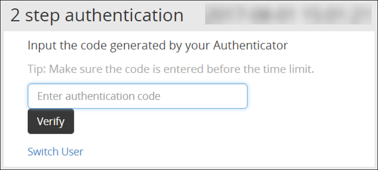
Click Sign in.The Two step authentication screen appears.

Scan the QR code using an authentication application.Alternatively, click the Can’t see QR code? link.A QR code gets generated and displayed below it as shown in the figure.

Enter the displayed code in the authentication app to generate One-time password.
In the Enter authentication code field box, enter the one-time password, and click Verify.
After the code is validated, the ESA home page appears.
5.2.2 - Working with Host-Based Shared-Secret
Describes the procedure to Host-Based Shared-Secret
Host-based shared-secret allows a common shared-secret for all users, which can be specified and distributed to the users by the Security Officer. Host-based shared-secret method is useful to force the same secret code for multiple appliances in clustered environments.
Configuring Two Factor Authentication with Host-Based Shared-Secret
The following section describes how to configure two factor authentication using host-based shared-secret.
Perform the following steps to configure Two Factor Authentication with Host-based shared-secret.
- On the ESA Web UI, navigate to Settings > Security > Two Factor Authentication.
- Check the Enable Two-Factor-Authentication check box.
- Select Host-based shared-secret from Authentication Mode.
- Click Modify.The Host-based shared-secret key appears.
If required, click Generate to modify the Host-based shared-secret key. Ensure that you note the Host-based shared-secret key to generate TOTP. - You can apply the following logging-settings in order to specify what to log:
- Log failed log-in attempts
- Log any successful log-ins
- Click Apply to save the changes. A confirmation message appears.
Logging in to the Web UI
Before beginning, be aware of time limits. When entering codes from the authenticator there is a time limit. Ensure codes are entered in the authenticator code box within the displayed time limit
The following section describes how to log in to the Web UI after configuring host-based shared-secret.
To login to the Web UI:
Navigate to the ESA Web UI login page.
In the Username and Password text boxes, enter the user credentials.
Click Sign in.
The 2 step authentication screen appears.

Use the Host-Based Shared-Secret key obtained from the configuration process to generate authentication code.
Enter the Host-Based Shared-Secret key in the authentication app to generate authentication code.
In the authenticator code box, enter the authentication code, and click Verify.
After the code is validated, the ESA home page appears.
5.2.3 - Working with Remote Authentication Dial-up Service (RADIUS) Authentication
Describes the procedure work with RADIUS Authentication
The Remote Authentication Dial-up Service (RADIUS) is a networking protocol for managing authentication, authorization, and accounting in a network. It defines a workflow for communication of information between the resources and services in a network. The RADIUS protocol uses the UDP transport layer for communication. The RADIUS protocol consists of two components, the RADIUS server and the RADIUS client. The server receives the authentication and authorization requests of users from the RADIUS clients. The communication between the RADIUS client and RADIUS server is authenticated using a shared secret key.
You can integrate the RADIUS protocol with an ESA for two-factor authentication. The following figure describes the implementation between ESA and the RADIUS server.

- The ESA is connected to the AD that contains user information.
- The ESA is a client to the RADIUS sever that contains the network and connection policies for the AD users. It also contains a RADIUS secret key to connect to the RADIUS server. The communication between the ESA and the RADIUS sever is through the Password Authentication Protocol (PAP).
- An OTP generator is configured with the RADIUS server. An OTP is generated for each user. Based on the secret key for each user, an OTP for the user is generated.
In ESA, the following two files are created as part of the RADIUS configuration:
- The dictionary file that contains the default list of attributes for the RADIUS server.
- The custom_attributes.json file that contains the customized list of attributes that you can provide to the RADIUS server.
Important : When assigning a role to the user, ensure that the Can Create JWT Token permission is assigned to the role.If the Can Create JWT Token permission is unassigned to the role of the required user, then remote authentication fails.To verify the Can Create JWT Token permission, from the ESA Web UI navigate to Settings > Users > Roles.
Configuring Radius Two-Factor Authentication
To configure Radius two-factor authentication:
On the ESA Web UI, navigate to Settings > Security > Two Factor Authentication.
Check the Enable Two-Factor-Authentication checkbox.
Select the Radius Server option as shown in the following figure.
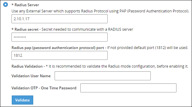
Type the IP address or the hostname of the RADIUS server in the Radius Server text box.
Type the secret key in the Radius Secret text box.
Type the port of the RADIUS server in the Radius port text box.Alternatively, the default port is 1812.
Type the username that connects to the RADIUS server in the Validation User Name text box.
Type the OTP code for the user in the Validation OTP text box.
Click Validate to validate the configuration.A message confirming the configuration appears.
Click Apply to apply the changes.
Logging in to the Web UI
Perform the following steps to login to the Web UI:
Open the ESA login page.
Type the user credentials in the Username and Password text boxes.
Click Sign-in.The following screen appears.
Type the OTP code and select Verify.After the OTP is validated, the ESA home page appears.
Editing the Radius Configuration Files
To edit the configuration files:
On the ESA Web UI, navigate to Settings > System.
Under OS-Radius Server tab, click Edit corresponding to the custom_attibutes.json or directory to edit the attributes.
If required, modify the attributes to the required values.
Click Save.The changes are saved.
Logging in to the CLI
Perform the following steps to login to CLI Manager:
Open the ESA CLI Manager.
Enter the user credentials.
Press ENTER .The following screen appears.
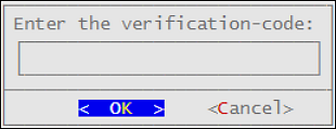
Type the verification code and select OK.After the code is validated, the main screen for the CLI Manager appears.
5.2.4 - Working with Shared-Secret Lifecycle
Describes the procedure work with shared-secret lifecycle
All users of appliance two factor authentication get a shared-secret for verification. This shared-secret for a user remains in the two factor authentication group list until it is manually deleted. Even if a user becomes ineligible to access the system, the username remains linked to the shared-secret.
This exception is valid for those users opting for per-user authentication.
If the same user or another user with the same name is again added to the system, then the user becomes eligible to use the already existing shared-secret.
To prevent this exception, ensure that an ineligible user is manually removed from the Two Factor Authentication group.
Revoking Shared-Secret for the User
The option to revoke shared-secret is useful when user needs to switch to another mobile device or the previous shared-secret cannot be retrieved from the earlier device.
Perform the following steps to revoke shared-secret for the user:
On the ESA Web UI, navigate to Settings > Security > Two Factor Authentication.
Ensure that the Enable Two-Factor-Authentication and Automatic per-user shared-secret checkbox are checked.
Inspect Users Shared Secrets area to identify user account to revoke.You can revoke users who have already logged in to the Appliance.
Click Revoke.
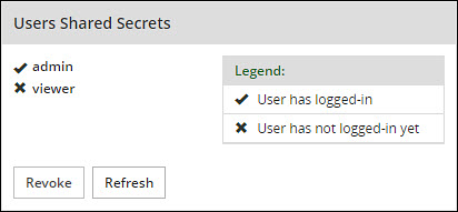
Select the user to discard by clicking the checkbox next to the username.
Click Apply to save the changes.A new shared-secret code will be created for the revoked user and is presented upon the next login.
5.2.5 - Logging in Using Appliance Two Factor Authentication
Describes the procedure to log in using the Two Factor Authentication
Perform the following steps to log in using Appliance Two Factor Authentication:
Navigate to ESA login page.
Enter your username.
Enter your password.
Click Sign in.After verification, a separate login dialog appears.

As a prerequisite, a new user must setup an account on Google Authenticator. Download the Google Authenticator app in your device and follow the instructions to create a new account.
Enter the shared-secret in your device.If the system is configured for per-user shared-secret, then this secret code is made available. If this is a web-session, then you are presented with a barcode and the applications that support it.
After you accept the shared-secret, the device displays a verification code.
Enter this verification code in the screen displayed in step 4.
Click Verify.
5.2.6 - Disabling Appliance Two Factor Authentication
Describes the procedure to disable the Two Factor Authentication
Perform the following steps to disable Two Factor Authentication:
Using the ESA Web UI, navigate to Settings > Security > Two Factor Authentication.
Clear the Enable Two-Factor-Authentication checkbox.
Click Apply to save the changes.
Disable Two Factor through local console
You can also disable two-factor authentication from the local console.You need to switch to OS console and execute the following command.
# /etc/opt/2FA/2fa.sh -–disable
5.3 - Working with Configuration Files
Describes the work with the configuration file
The Product Files screen displays the configuration files of all the products that are installed in ESA. You can view, modify, delete, upload, or download the configuration files from this screen. In the ESA Web UI, navigate to Settings > System > Files to view the configuration files.
The following table describes the different products and their respective configuration files that are available in ESA.
| Product | Configuration Files | Description |
| OS – Radius Server | Dictionary | Contains the dictionary translations for analyzing requests and generating responses for RADIUS server. |
| custom_attributes.json | Contains the configuration settings of the header data for the RADIUS server. | |
| OS –Export/Import | Customer.custom | Lists the custom files that can be exported or
imported. For more information about exporting custom files, refer here. |
| Audit Store-SMTP Config Files | smtp_config.json | Contains the SMTP configuration settings for sending email alerts. |
| smtp_config.json.example | Contains SMTP configuration settings and example values for sending email alerts. This is a template file. | |
| Policy Management – Member Source Service User Files | exampleusers.txt | Lists the users that can be used in policy. For more
information about policy users, refer Policy Management. |
| Policy Management – Member Source Service Group Files | examplegroups.txt | Lists the user groups that can be used in policy. For
more information about policy user groups, refer Policy Management.
. |
| Settings → System → Files → Downloads - Other files | contractual.htm | Lists all the third-party software licenses that are
utilized in ESA.NoteYou cannot modify the file. |
| Distributed Filesystem File Protector – Configuration Files | dfscacherefresh.cfg | Contains the DFSFP configuration settings such as, logging,
SSL, Security, and so on. For more information about the
dfscacherefresh.cfg file, refer to the
Protegrity Big Data Protector Guide 9.2.0.0
.NoteStarting
from the Big Data Protector 7.2.0 release, the HDFS File Protector
(HDFSFP) is deprecated. The HDFSFP-related sections are retained
to ensure coverage for using an older version of Big Data
Protector with the ESA 7.2.0. |
| Cloud Gateway –Settings | gateway.json | Lists the log level settings for Data Security Gateway. For more information about the
gateway.json file, refer to the Protegrity Data Security Gateway User Guide
3.2.0.0. |
| alliance.conf | Configuration file to direct syslog events between servers over TCP or UDP. |
The following figure illustrates various actions that you can perform on the Product Files screen.
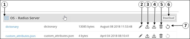
| Callout | Description | Action |
|---|---|---|
| 1 | Collapse/Expand | Collapse or expand to view the configuration files. |
| 2 | Edit | Edit the configuration file. |
| 3 | Upload | Upload a configuration file.Note: When you upload a file, it replaces the existing file in the system. |
| 4 | Download | Download the file to your local system. |
| 5 | Delete | Delete the file from the system. |
| 6 | Download | Download all the files of the product to your local system. |
| 7 | Reset | Reset the configuration to the previously saved settings. |
Viewing a Configuration File
You can view the contents of the configuration file from the Web UI. If the file size is greater than 5 MB, you must download the file to view the contents.
Perform the following steps to view a file:
Navigate to Settings > System > Files.The screen with the files appears.
Click on the required file. The contents of the file appear.
You can modify, download, or delete the file using the Edit, Download and Delete icon respectively.
Uploading a Configuration File
Configuration files can be uploaded using this option.For more information about the configuration files, refer Working with Configuration Files.
Perform the following steps to upload a file.
- Navigate to Settings > System > Files.The screen with the files appears.
- Click on the upload icon.The file browser icon appears.
- Select the configuration file and click Upload File.A confirmation message appears.
- Click Ok.A message confirming the upload appears.
Modifying a Configuration File
In addition to editing the file from the Files screen, you can also modify the content of the file from the view option. If you want to modify the content of a file whose size is greater than 5 MB, you must download the file to the local machine, modify the content, and then upload the file through the Web UI.
For instructions to download a configuration file, refer here.
Perform the following steps to modify a file.
- Navigate to Settings > System > Files.The screen with the files appears.
- Click on the required file.The contents of the file appear.
- Click the Edit to modify the file.
- Perform the required changes and click Save.A message confirming the changes appears.
Deleting a Configuration File
In addition to deleting the file from the Files screen, you can also delete the file from the view option. After you delete the file, an exclamation icon appears indicating that the file does not exist on the server. Using the reset functionality, you can restore the deleted file.
Perform the following steps to delete a file.
- Navigate to Settings > System > Files.The screen with the files appears.
- Click on the required file.The contents of the file appear.
- Click the Delete icon to modify the file.A message confirming the deletion appears.
- Select Yes.
Resetting a File
The Reset functionality is used to restore the changes that are done to your file. For every configuration file, the Reset icon is disabled. This icon is enabled when you perform any of the following changes:
- Modify the configuration file
- Delete the configuration file
When you modify or delete a file, the original file is backed up in the /etc/configuration-files-backup directory. For every modification, the file in the directory is overwritten. When you click the Reset icon, the file is retrieved from the directory and restored on the Files screen.
Perform the following steps to restore a file.
- Navigate to Settings > System > Files.The screen with the files appears.
- Click the Reset icon to restore a file.The file that is edited or deleted is restored.
Limits on resetting files
Only the changes that are performed on the files through the Web UI are backed up. Changes performed on the files through the CLI Manager are not backed up and cannot be restored.
5.4 - Working with File Integrity
Describes working with the file integrity option
The content modifications can be viewed by the Security Officer since the PCI specifications require that sensitive files and folders in the Appliance are monitored. This information contains password, certificate, and configuration files. The File Integrity Monitor makes a weekly check and all changes made to these files can be reviewed by authorized users.

To check file modifications at any given time, click Settings > Security > File Integrity > Check. The Security Officer views and accepts the changes, writing comments as necessary, in the comment box. Accepting changes means that the changes are removed from the viewable list. Changes cannot be rejected. You must not accept deletion of system files. These files must be available.
Only the last modification made to a file appears.
All the changes can also be viewed on the Audit Store > Dashboard > Discover screen. Another report shows all accepted changes. For more information about Discover, refer Discover.
Before applying a patch, it is recommended to check the files and accept the required changes under Settings > File Integrity > Check.
After installing the patches for appliances such as ESA or DSG, check the files and accept the required changes again under Settings > Security > File Integrity > Check.
5.5 - Managing File Uploads
Describes the procedure to manage file uploads
You can upload a patch file of any size from the File Upload screen in the ESA Web UI. The files uploaded from the Web UI are available in the /opt/products_uploads directory.
After the file is uploaded, in the Uploaded Files section, select the file to view the file information, download it, or delete it.
To upload a file:
Navigate to Settings > System > File Upload.The File Upload page appears.
In the File Selection section, click Choose File.The file upload dialog box appears.
Select the required file and click Open.
- You can only upload files with .pty and .tgz extensions.
- If the file uploaded exceeds the Max File Upload Size, then a password prompt appears. Only a user with the administrative role can perform this action. Enter the password and click Ok.
- By default, the Max File Upload Size value is set to 25 MB. To increase this value, refer here.
Click Upload.The file is uploaded to the
/opt/products_uploadslocation.- If a file contains spaces in its name, then it will be automatically replaced with underline character (_).
- The files are scanned by the internal AntiVirus before they are uploaded in the ESA.
- If the FIPS mode is enabled, then the anti-virus scan is skipped during the file upload.
- The SHA512 checksum value is validated during the upload process.
- If the network is interrupted while uploading the file, then the ESA retries to upload the file.The retry upload process is attempted ten times. Each attempt lasts for ten seconds.
After the file is uploaded successfully, then from the Uploaded Files area, choose the uploaded patch.The information for the selected patch appears.

Verifying uploaded file integrity
To verify the integrity of the uploaded file, validate the checksum values displayed on the screen with the checksum values of the downloaded patch file.You can obtain the checksum values from the My.Protegrity or contact Protegrity Support.
5.6 - Configuring Date and Time
Describes the procedure to configure date and time
You can use the Date/Time tab to change the date and time settings. To update the date and time, navigate to Settings > System > Date/Time.
The Date and Time screen with the Update Time Periodically option enabled is shown in the following figure.

The date and time options are described in the following table.
| Setting | Details | How to configure/change |
|---|---|---|
| Update Time Periodically | Synchronize the time with the specified NTP Server, upon boot and once an hour. | You can enable this option using Enable button and disable it using Disable. Only enable or disable NTP settings from the CLI Manager or the Web UI. |
| Current Appliance Date/Time | Manually synchronize the time with the specified NTP Server. You can use NTP Server synchronization only if NTP service is running. | You can force and restart time synchronization using Reset NTP Sync. You can display NTP analysis using NTP Query button. |
| Set Time Zone | Specify the time zone for your appliance. | Select your local time zone from the Set Time Zone list and click Set Time Zone. |
| Set Manually Date/Time (mm/dd/yyyy hh:mm) | Set the time manually. | Type the date and time using the format mm/dd/yyyy hh/mm. Click Set Date/Time.Note: The Set Manually Date/Time (mm/dd/yyyy hh:mm) text box appears only if the Update Time Periodically functionality is disabled. |
5.7 - Configuring Email
Describes the procedure to configure Email
The SMTP setting allows the system to send emails.

You can test that the email works by clicking Test. Error logs can be viewed on the Audit Store > Dashboard > Discover screen.
For more information about Discover, refer Working with Discover.
Some scripts run after you click Save.Ensure to save the details only when the connection is intact.

If the email address cannot be authenticated, then the Show Test Communication area displays the communication between the appliance and the SMTP server for debugging.
5.8 - Configuring Network Settings
Describes the procedure to configure the network settings
On the Network Settings screen, you can configure the network details for the ESA. The following table explains the different settings that can be configured.
Information in the following table is specific to the Web UI. For information on the same features and configuring them in the CLI, refer here.
| Setting | Details | How to configure/change |
|---|---|---|
| Hostname | The hostname is a unique name for a system or a node in a network.Ensure that the hostname does not contain the dot(.) special character. | Click Apply on the Web UI or change the hostname of the appliance from the Network Settings screen in the CLI Manager. |
| Management IP | The management IP, which is the IP address of the appliance, is defined through CLI Manager. | Select Blink to identify the interface. This will cause a LED on the NIC to blink and then click Change. |
| Default Route | The default route is an optional destination for all network traffic that does not belong to the LAN segment. For example, the IP address of your LAN router in the IP address format is 172.16.8.12. It is required only if the appliance is on a different subnet than the Appliance Web Interface. | Click Apply to set the default route. |
| Domain | The appliance domain name specified during appliance installation. | You can change it by specifying a new name and clicking Apply. |
| Search Domains | The appliance can belong to one domain and search an additional three domains. | You can add them using Add button. |
| Domain Name Servers | If your appliance uses domain names and IP addresses, then you must configure a domain name server (DNS) to help resolve Internet name addresses. The domain name should be for your local network, like Protegrity.com or math.mit.edu and the name servers should be IP addresses. The appliance can use up to three DNS servers for name resolving. Once you have configured a DNS, the system can be managed using an SSH connection. | You can add them using Add button, and remove them using Remove. You can specify them using Apply button. |
5.8.1 - Managing Network Interfaces
Describes the procedure to manage the network interfaces
Using Settings > Network > Network Settings, you can view appliance network interfaces names and addresses and add them from the Interfaces page.

Changes to IP addresses
Changes to IP addresses are immediate. Changes to the management IP (on ethMNG), while connected via SSH or the Appliance Web Interface, causes the session to disconnect.
Assigning an Address to an Interface
Perform the following steps to assign an address to an interface.
- Navigate to Settings > Network.
- Click Network Settings.The Interfaces page appears.
- Identify the interface on the appliance by clicking Blink for the interface you want to identify.Select a LED on the NIC that blinks to indicate that interface.
- In the Interface row, type the address and Net mask of the interface, and then click Add.
Assigning an Address to an Interface Using Web UI
Perform the following steps to assign an address to an interface.
- In the Web UI, navigate to Settings > Network > Network Settings.The Network Settings page appears.
- In the Network Interfaces area, select Add New IP in the Gateway column.
Ensure that the IP address for the NIC is added. - Enter the IP address of the default gateway and select OK.The default gateway for the interface is added.
5.8.2 - NIC Bonding
Describes the procedure to manage the NIC interfaces
The Network Interface Card (NIC) is a device through which appliances, such as ESA or DSG, on a network connect to each other. If the NIC stops functioning or is under maintenance, the connection is interrupted, and the appliance is unreachable. To mitigate the issues caused by the failure of a single network card, Protegrity leverages the NIC bonding feature for network redundancy and fault tolerance. In NIC bonding, multiple NICs are configured on a single appliance. You then bind the NICs to increase network redundancy. NIC bonding ensures that if one NIC fails, the requests are routed to the other bonded NICs. Thus, failure of a NIC does not affect the operation of the appliance. You can bond the configured NICs using different bonding modes.
Bonding Modes
The bonding modes determine how traffic is routed across the NICs. The MII monitoring (MIIMON) is a link monitoring feature that is used for inspecting the failure of NICs added to the appliance. The frequency of monitoring is 100 milliseconds. The following modes are available to bind NICs together:
- Mode 0/Balance Round Robin
- Mode 1/Active-backup
- Mode 2/Exclusive OR
- Mode 3/Broadcast
- Mode 4/Dynamic Link Aggregation
- Mode 5/Adaptive Transmit Load Balancing
- Mode 6/Adaptive Load Balancing
The following two bonding modes are supported for appliances:
- Mode 1/Active-backup policy: In this mode, multiple NICs, which are slaves, are configured on an appliance. However, only one slave is active at a time. The slave that accepts the requests is active and the other slaves are set as standby. When the active NIC stops functioning, the next available slave is set as active.
- Mode 6/Adaptive load balancing: In this mode, multiple NICs are configured on an appliance. All the NICs are active simultaneously. The traffic is distributed sequentially across all the NICs in a round-robin method. If a NIC is added or removed from the appliance, the traffic is redistributed accordingly among the available NICs. The incoming and outgoing traffic is load balanced and the MAC address of the actual NIC receives the request. The throughput achieved in this mode is high as compared to Mode 1/Active-backup policy.
Prerequisites
Ensure that you complete the following pre-requisites when binding interfaces:
- The IP address is assigned only to the NIC on which the bond is initiated. You must not assign an IP address to the other NICs.
- The NIC is not configured on an HA setup.
- The NICs are on the same network.
Creating a Bond
The following procedure describes the steps to create a bond between NICs. For more information about the bonding nodes, refer here.
Ensure that the IP address of the slave nodes are static.
Perform the following steps to create a bond.
On the Web UI, navigate to Settings > Network > Network Settings.The Network Settings screen appears.
Under the Network Interfaces area, click Create Bond corresponding to the interface on which you want to initiate the bond.The following screen appears.
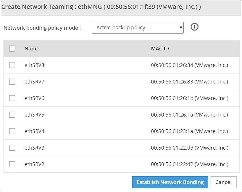
Ensure that the IP address is assigned to the interface on which you want to initiate the bond.
Select the following modes from the drop-down list:
- Active-backup policy
- Adaptive Load Balancing
Select the interfaces with which you want to create a bond.
Select Establish Network Bonding.A confirmation message appears.
Click OK.The bond is created, and the list appears on the Web UI.
Removing a Bond
Perform the following steps to remove a bond:
- On the Web UI, navigate to Settings > Network > Network Settings.The Network Settings screen appears with all the created bonds as shown in the following figure.
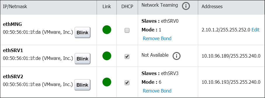
Under the Network Interfaces area, click Remove Bond corresponding to the interface on which the bonding is created.A confirmation screen appears.
Select OK.The bond is removed and the interfaces are visible on the IP/Network list.
Viewing a Bond
Using the DSG CLI Manager, you can view the bonds that are created between all the interfaces.
Perform the following steps to view a bond:
On the DSG CLI Manager, navigate to Networking > Network Settings.The Network Configuration Information Settings screen appears.
Navigate to Interface Bonding and select Edit.The Network Teaming screen displaying all the bonded interfaces appears as shown in the following figure.
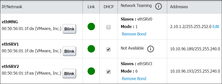
Resetting the Bond
You can reset all the bonds that are created for an appliance. When you reset the bonds, all the bonds created are disabled. The slave NICs are reset to their initial state, where you can configure the network settings for them separately.
Perform the following steps to reset all the bonds:
On the DSG CLI Manager, navigate to Networking > Network Settings.The Network Configuration Information Settings screen appears.
Navigate to Interface Bonding and select Edit.The Network Teaming screen displaying all the bonded interfaces appears.
Select Reset.The following screen appears.
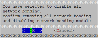
- Select OK.The bonding for all the interfaces is removed.
5.9 - Configuring Web Settings
Describes the procedure to configure the Web settings
Navigate to Settings > Network > Web settings, the Web Settings page contains the following sections:
- General Settings
- Session Management
- Shell In A Box Settings
- SSL Cipher Settings
5.9.1 - General Settings
Describes the General settings
The General Settings contains the following file upload configurations:
- Max File Upload Size
- File Upload Chunk Size
Increasing Maximum File Upload Size
By default, the maximum file upload size is set to 25 MB. You can increase the limit up to 4096 MB.
Perform the following steps to increase the maximum file upload size:
- From the ESA Web UI, proceed to Settings > Network > Web Settings.The Web Settings screen appears.

Move the Max File Upload Size slider to the right to increase the limit.
Click Update.
Increasing File Upload Chunk Size
By default, the file upload chunk size is set to 100 MB. You can increase the limit up to 512 MB.
Perform the following steps to increase the file upload chunk size:
- From the ESA Web UI, proceed to Settings > Network > Web Settings.The Web Settings screen appears.
Move the File Upload Chunk Size slider to the right to increase the limit.
Click Update.
5.9.2 - Session Management
Describes the procedure to manage the session
Only the admin user can extend the time using this option. The extended time becomes applicable to all users of the ESA.
Managing the session settings
Only the admin user can extend the time using this option. The extended time becomes applicable to all users of the ESA.
Perform the following steps to timeout using ESA Web UI option:
From the ESA Web UI, proceed to Settings > Network.
Click Web Settings.The following screen appears.

Move the Session Timeout slider to the right to increase the time, in minutes.
Click Update.
Fixing the Session Timeout
Perform the following steps to fix the session timeout.
There may be cases where the timeout session should be fixed, and the appliance logs out even if the session is an active session.
From the ESA Web UI, proceed to Settings > Network.
Click Web Settings.The following screen appears.
Move the Session Timeout slider to the right or left to increase or decrease the time, in minutes.
Select the Is hard timeout check box.
Click Update.
5.9.3 - Shell in a box settings
Describes the shell in a box settings
This setting allows a user with Appliance Web Manager permission to configure access to the Shell In A Box feature which is available through the Web UI. This setting applies to all the users that have access to the Web UI.
When enabled the users are able to view the CLI icon on the bottom right corner of the web page.
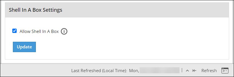
Perform the following steps to enable/disable Shell In A Box Settings.
From the ESA Web UI, proceed to Settings > Network.
Click Web Settings.The following screen appears.

To enable or disable the Shell In a Box Settings, select the Allow Shell In a Box check box.
Click Update.
5.9.4 - SSL cipher settings
Describes the SSL cipher settings
The ESA uses the OpenSSL library to encrypt and secure connections. You can configure an encrypted connection using the following two strings:
- SSL Protocols
- SSL Cipher Suites
The protocols and the list of ciphers supported by the ESA are included in the SSLProtocol and SSLCipherSuite strings respectively. The SSLProtocol supports SSL v2, SSL v3, TLS v1, TLS v1.1, TLS v1.2, and TLS v1.3 protocols.
To disable any protocol from the SSLProtocol string, prepend a hyphen (-) to the protocol. To disable any cipher suite from the SSLCipherSuite string, prepend an exclamation (!) to the cipher suite.
For more information about the OpenSSL library, refer to http://www.openssl.org/docs.
Using TLS v1.3
The TLS v1.3 protocol is introduced from v8.1.0.0. If you want to use this protocol, then ensure that you append the following cipher suite in the SSLCipherSuite text box.
TLS_AES_256_GCM_SHA384:TLS_CHACHA20_POLY1305_SHA256:TLS_AES_128_GCM_SHA256:ECDHE-RSA-AES128-GCM-SHA256:ECDHE-ECDSA-AES128-GCM-SHA256:ECDHE-RSA-AES256-GCM-SHA384:ECDHE-ECDSA-AES256-GCM-SHA384:DHE-RSA-AES128-GCM-SHA256:DHE-DSS-AES128-GCM-SHA256:kEDH+AESGCM:ECDHE-RSA-AES128-SHA256:ECDHE-ECDSA-AES128-SHA256:ECDHE-RSA-AES128-SHA:ECDHE-ECDSA-AES128-SHA:ECDHE-RSA-AES256-SHA384:ECDHE-ECDSA-AES256-SHA384:ECDHE-RSA-AES256-SHA:ECDHE-ECDSA-AES256-SHA:DHE-RSA-AES128-SHA256:DHE-RSA-AES128-SHA:DHE-DSS-AES128-SHA256:DHE-RSA-AES256-SHA256:DHE-DSS-AES256-SHA:DHE-RSA-AES256-SHA:AES128-GCM-SHA256:AES256-GCM-SHA384:AES128-SHA256:AES256-SHA256:AES128-SHA:AES256-SHA:AES:CAMELLIA:!aNULL:!eNULL:!EXPORT:!DES:!RC4:!MD5:!PSK:!aECDH:!EDH-DSS-DES-CBC3-SHA:!EDH-RSA-DES-CBC3-SHA:!KRB5-DES-CBC3-SHA
5.9.5 - Updating a protocol from the ESA Web UI
Describes the procedure to update a protocol using the ESA Web UI
Perform the following steps to update a protocol from the ESA Web UI:
In the ESA Web UI, navigate to Settings > Network > Web Settings.The Web Settings page appears.
Under SSL Cipher Settings tab, the SSLProtocol text box contains the value ALL-SSLv2-SSLv3.
Add
–to the required protocol.For example, to disable TLS1.1, type -TLSv1.1 in the SSLProtocol text box.

- Click Update to save the changes.
To re-enable TLSv1.1 using the Web UI, remove –TLSv1.1 from the SSLProtocol text box.
5.10 - Working with Secure Shell (SSH) Keys
Describes the procedure to configure the SSH Keys
The Secure Shell (SSH) is a network protocol that ensures an secure communication over unsecured network. A user connects to the SSH server using the SSH Client. The SSH protocol is comprised of a suite of utilities which provides high-level authentication encryption over unsecured communication channels.
A typical SSH setup consists of a host machine and a remote machine. A key pair is required to connect to the host machine through any remote machine. A key pair consists of a Public key and a Private key. The key pair allows the host machine to securely connect to the remote machine without entering a password for authentication.
For enhancing security, a Private key is secured using a passphrase. This ensures that only the rightful recipient can have access to the decrypted data. You can either generate key pairs or work with existing key pairs.
If you add a Private key without a passphrase, it is encrypted with a random passphrase. This passphrase is scrambled and stored.
If you choose a Private key with a passphrase, then the Private key is stored as it is. This passphrase is scrambled and stored.
For more information about generating the SSH key pairs, refer Adding a New Key.
The SSH protocol allows an authorized user to connect to the host machines from the remote machines. Both inbound communication and outbound communication are supported using the SSH protocol. An authorized user is a combination of an appliance user associated with a valid key pair. An authorized user must be listed as a valid recipient to connect using the SSH protocol.
The SSH protocol allows the authorized users to run tasks securely on the remote machine. When the users connect to the appliance using the SSH protocol, then the communication is known as inbound communication.
For more information about inbound SSH configuration, refer here.
When the users connect to a known host using their private keys, then the communication is known as outbound communication. The authorized users are allowed to initiate the SSH communication from the host.
For more information about outbound SSH configuration, refer here.
On the ESA Web UI, you can configure all the following standard aspects of SSH:
- Authorized Keys
- Identities Keys
- Known Hosts
SSH pane:With the SSH configuration Manager you can examine and manage the SSH configuration. The SSH keys can be configured in the Authentication Configuration pane on the ESA Web UI.
The following figure shows the SSH Configuration Manager pane.

Authentication Type:The SSH Server is configured in the following three ways:
- Password
- Public Key
- Password + publickey
| Authentication Type | Description |
|---|---|
| Password | In this authentication type, only the password is required for authentication to the SSH server. The public key is not required on the server for authentication. |
| Public Key | In this authentication type, the server requires only the public key for authentication. The password is not required for authentication. |
| Password + Public key | In this authentication type, the server can accept both, the keys and the password, for authentication. |
SSH Mode:
From the Web UI, navigate to Settings > Network > SSH. Using the SSH mode, restrictions for SSH connections can be set. The restrictions can be hardened or loosened based on the needs. There are four modes SSH mode types are shown below.
| Mode | SSH Server | SSH Client |
|---|---|---|
| Paranoid | Disable root access | Disable password authentication, that is, allow to connect only using public keys. Block connections to unknown hosts. |
| Standard | Disable root access | Allow password authentication. Allow connections to new (unknown) hosts, enforce SSH fingerprint of known hosts. |
| Open | Allow root access Accept connections using passwords and public keys. | Allow password authentication. Allow connection to all hosts – do not check hosts fingerprints. |
5.10.1 - Configuring the authentication type for SSH keys
Describes the procedure to configure the authentication type for SSH Keys
Perform the following steps to configure the SSH Key Authentication Type.
From the ESA Web UI, navigate to Settings > Network.The Network Settings pane appears.
Select the SSH tab.The SSH Configuration Manager pane appears.
Select the authentication type from the Authentication Type drop down menu.

Select the SSH mode from the SSH Mode drop down menu.
Click Apply.A message Configuration saved successfully appears.
5.10.2 - Configuring inbound communications
Describes the procedure to configure the inbound communication for SSH Keys
The users who are allowed to connect to the ESA using SSH are listed in the Authorized Keys (Inbound) tab.
The following screen shows the Authorized Keys.
")
Adding a New Key
An authorized key has to be created for a user or a machine to connect to an ESA on the host machine.
Perform the following steps to add a new key.
From the ESA Web UI, navigate to Settings > Network.The Network Settings pane appears
Select the SSH tab.The SSH Configuration Manager pane appears.
Select the Authorized Keys (Inbound) tab.
Click Add New Key.The Add New Authorized Key dialog box appears.
Select a user.
Select Generate new public key.
The Root password is required to create Authorized Key prompt appears. Enter the root password and click Ok.
If the private key is to be saved, then select Click To Download Private Key.The private key is saved to the local machine.
If the public key is to be saved, then select Click To Download Public Key.The public key is saved to the local machine.
Click Finish.The new authorized key is added.
Uploading a Key
You can assign a public key to a user by uploading the key from the Web UI.
Perform the following steps to upload a key.
From the ESA Web UI, navigate to Settings > Network.The Network Settings pane appears.
Select the SSH tab.The SSH Configuration Manager pane appears.
Select the Authorized Keys (Inbound) tab.
Click Add New Key.The Add New Authorized Key dialog box appears.
Select a user.
Select Upload public key.The file browser dialog box appears.
Select a public key file.
Click Open.
The Root password is required to create Authorized Key prompt appears. Enter the root password and click Ok.The key is assigned to the user.
Reusing public keys between users
The public key of one user can be assigned as a public key of another user.
Perform the following steps to upload an existing key.
From the ESA Web UI, navigate to Settings > Network.The Network Settings pane appears.
Select the SSH tab.The SSH Configuration Manager pane appears.
Select the Authorized Keys (Inbound) tab.
Click Add New Key.The Add New Authorized Key dialog box appears.
Select a user.
Select Choose from existing keys.
Select the public key.
The Root password is required to create Authorized Key prompt appears. Enter the root password and click Ok.The public key is assigned to the user.
Downloading a Public Key
From the Web UI, you can download the public of a user to the local machine.
Perform the following steps to download a key.
From the ESA Web UI, navigate to Settings > Network.The Network Settings pane appears.
Select the SSH tab.The SSH Configuration Manager pane appears.
Select the Authorized Keys (Inbound) tab.
Select a user.
Select Download Public Key.The public key is saved to the local directory.
Deleting an Authorized Key
You can remove a key from the authorized users list. Once the key is removed from the list, the remote machine will no longer be able to connect to the host machine.
Perform the following steps to delete an authorized key:
From the ESA Web UI, navigate to Settings > Network.The Network Settings pane appears
Select the SSH tab.The SSH Configuration Manager pane appears.
Select the Authorized Keys (Inbound) tab.
Select a user.
Select Delete Authorized Key.A message confirming the deletion appears.
Click Yes.
The Root password is required to delete Authorized Key prompt appears. Enter the root password and click Ok.The key is deleted from the authorized keys list.
Clearing all Authorized Keys
You can remove all the public keys from the authorized keys list.
Perform the following steps to clear all keys:
From the ESA Web UI, navigate to Settings > Network.The Network Settings pane appears.
Select the SSH tab.The SSH Configuration Manager pane appears.
Select the Authorized Keys (Inbound) tab.
Click Reset List.A message confirming the deletion of all authorized keys appears.
Click Yes.
The Root password is required to delete all Authorized Keys prompt appears. Enter the root password and click Ok.All the keys are deleted.
5.10.3 - Configuring outbound communications
Describes the procedure to configure the outbound communication for SSH Keys
The users who can connect to the known hosts with their private keys are listed in the Identities Keys (Outbound) tab.
The following screen shows the Identities.
")
Adding a New Key
A new public key can be generated for the host machine to connect with another machine.
Perform the following steps to add a new key.
From the ESA Web UI, navigate to Settings > Network.The Network Settings pane appears.
Select the SSH tab.The SSH Configuration Manager pane appears.
Select the Identities Keys (Outbound) tab.
Click Add New Key.The Add New Identity Key dialog box appears.
Select a user.
Select Generate new keys.
The Root password is required to create Identity Key prompt appears. Enter the root password and click Ok.
If the public key is to be saved, then select Click to Download Public Key .The public key is saved to the local machine.
Click Finish.The new authorized key is added.
Downloading a Public Key
You can download the host’s public key from the Web UI.
Perform the following steps to download a key.
From the ESA Web UI, navigate to Settings > Network.The Network Settings pane appears.
Select the SSH tab.The SSH Configuration Manager pane appears.
Select the Identities Keys (Outbound) tab.
Select a user.
Select Download Public Key.The public key is saved to the local machine.
Uploading Keys
Perform the following steps to upload an existing key.
From the ESA Web UI, navigate to Settings > Network.The Network Settings pane appears.
Select the SSH tab.The SSH Configuration Manager pane appears.
Select the Identities Keys (Outbound) tab.
Click Add New Key.The Add New Identity Key dialog box appears.
Select a user.
Select Upload Keys.The list of public keys with the users that they are assigned to appears.
Select Upload Public Key.The file browser dialog box appears.
Select a public key file from your local machine.
Click Open.The public key is assigned to the user.
Select Upload Private Key.The file browser dialog box appears.
Select a private key file from your local machine.
Click Open.
If the private key is protected by a passphrase, then the text field Private Key Passphrase appears.Enter the private key passphrase.

- Click Finish.The new identity key is added.
Reusing public keys between users
The public and private key pair of one user can assigned as a public and private key pair of another user.
Perform the following steps to choose from an existing key.
From the ESA Web UI, navigate to Settings > Network.The Network Settings pane appears.
Select the SSH tab.The SSH Configuration Manager pane appears.
Select the Identities Keys (Outbound) tab.
Click Add New Key.The Add New Identity Key dialog box appears.
Select a user.
Select Choose from existing keys.
Select the public key.
The Root password is required to create Identity Key prompt appears. Enter the root password and click Ok.The public key is assigned to the user.
Deleting an Identity
You can delete an identity for a user. Once the identity is removed, the user will no longer be able to connect to another machine.
Perform the following steps to delete an identity:
From the ESA Web UI, navigate to Settings > Network.The Network Settings pane appears.
Select the SSH tab.The SSH Configuration Manager pane appears.
Select the Identities Keys (Outbound) tab.
Select a user.
Click Delete Identity.A message confirming the deletion appears.
Click Yes.
The Root password is required to delete the Identity Key prompt appears. Enter the root password and click Ok.The identity is deleted.
Clearing all Identities
You can remove all the public keys from the authorized keys list.
Perform the following steps to clear all identities.
From the ESA Web UI, navigate to Settings > Network.The Network Settings pane appears.
Select the SSH tab.The SSH Configuration Manager pane appears.
Select the Identities Keys (Outbound) tab.
Click Reset Identity List.A message confirming the deletion of all identities appears.
Click Yes.
The Root password is required to delete all Identity Keys prompt appears. Enter the root password and click Ok.All the identities are deleted.
5.10.4 - Configuring known hosts
Describes the procedure to configure the known hosts for SSH Keys
By default, the SSH is configured to deny all the communications to unknown remote servers. Known hosts list the machines or nodes to which the host machine can connect to. The SSH servers to which the host can communicate with are added under Known Hosts.
Adding a New Host
You can add a host to the list of known hosts that can have a connection established.
Perform the following steps to add a host.
From the ESA Web UI, navigate to Settings > Network.The Network Settings pane appears.
Select the SSH tab.The SSH Configuration Manager pane appears.
Select the Known Hosts tab.
Click Add Host.The Enter the ip/hostname dialog box appears.
Enter the IP address or hostname in the Enter the ip/hostname text box.
Click Ok.All host is added to the known hosts list.
Updating the Host Keys
You can refresh the hostnames to check for updates to host’s public keys.
Perform the following steps to updated a host key.
From the ESA Web UI, navigate to Settings > Network.The Network Settings pane appears.
Select the SSH tab.The SSH Configuration Manager pane appears.
Select the Known Hosts tab.
Select a host name.
Click Refresh Host Key.The key for the host name is updated.
Deleting a Host
If a connection to a host is no longer required, then you can delete the host from the known host list.
Perform the following steps to delete a known host.
From the ESA Web UI, navigate to Settings > Network.The Network Settings pane appears.
Select the SSH tab.The SSH Configuration Manager pane appears.
Select the Known Hosts tab.
Select a host name.
Click Delete Host.A message confirming the deletion appears.
Click Yes.The host is deleted.
Resetting the Host Keys
You can set the keys of all the hosts to a default value.
Perform the following steps to reset all the host keys:
From the ESA Web UI, navigate to Settings > Network.The Network Settings pane appears.
Select the SSH tab.The SSH Configuration Manager pane appears.
Select the Known Hosts tab.
Select Reset Host Keys.A message confirming the reset appears.
Click Yes.The host keys for all the hostnames is set to a default value.
6 - Managing Appliance Users
Describes the appliance users
Only authorized users can access the Appliances. These users are system users and LDAP administrative users. The roles of these users are explained in detail in the following sections.
Appliance Users
The root and local_admin users are appliance system users. These users are initialized during installation.
root and local_admin
As a root user, you can be asked to provide the root account password to log in to some CLI Manager tools. For example, Change Accounts and Passwords tool or Configure SSH tool.
The root account is used to exit the appliance command line interface and go directly into the host operating system command line. This gives the system administrator full control over the machine.
The local_admin is necessary for LDAP maintenance when the LDAP is not working or is not accessible.
For on cloud instances, the SSH permissions for local_admin are available by default.However, for on-prem deployments, ensure to configure the SSH permissions for the local_admin.For information about SSH, refer Configuring the SSH.
LDAP Users
The admin and viewer user accounts are LDAP users that are initialized during installation.
For more information about users, refer here.
admin and viewer Accounts
The admin and viewer accounts are used to log onto CLI Manager or Appliance Web UI. These user accounts can be modified using:
- CLI Manager, for instructions refer to section Accounts and Passwords.
- Web UI, where these accounts are the part of the LDAP.
- Policy management.
When these passwords are changed in the CLI Manager or Appliance Web UI, the change applies to all other installed components, thus synchronizing the passwords automatically.
LDAP Target Users
When you have your appliance installed and configured, you can create LDAP users and assign necessary permissions to these users. You can also create groups of users. The system users are by default predefined in the internal LDAP directory.
For more information about creating users in LDAP and defining their security permissions, refer here.
System Roles
Protegrity Data Security Platform role-based access defines a list of roles, including a list of operations that a role can perform. Each user is assigned to one or more roles. User-based access defines a user to whom the operations are granted. There are several predefined roles on ESA.
The following table describes these roles.
| Role | Is used by… |
|---|---|
| root user | The OS system administrator who maintains the Appliance machine, which could be ESA or DSG. |
| admin user | The user who specifically manages the creation of roles and members in the LDAP directory. This user could also be the DBA, System Administrator, Programmer, and others. This user is responsible for installing, integrating, or monitoring Protegrity platform components into their corporate infrastructure for the purpose of implementing the Protegrity-based data protection solution. |
| viewer user | Personnel who can only view and not create or make changes. |
7 - Password Policy for all appliance users
Describes the password policy for all appliances users
The password policy applies to all LDAP users.
The LDAP user password should:
- Be at least 8 characters long
- Contain at least two of the following three character groups:
- Numeric [0-9]
- Alphabetic [a-z, A-Z]
- Special symbols, such as: ~ ! @ # $ % ^ & * ( ) _ + { } | : " < > ? ` - = [ ] \ ; ’ , . /
Thus, your password should look like one of the following examples:
- Protegrity123 (alphabetic and numeric)
- Protegrity!@#$ (alphabetic and special symbols)
- 123!@#$ (numeric and special symbols)
The strength of the password is validated by default. This strength validation can also be customized by creating a script file to meet the requirements of your organization.
From the CLI, press Administration > Accounts and Passwords > Manage Passwords and Local-Accounts. Select the correct Change option and update the password.
You can enforce organization rules for password validity from the Web UI, from Settings > Users > User Management, where the following can be configured:
- Minimum period for changeover
- Password expiry
- Lock on maximum failures
- Password history
For more information about configuring the password policy, refer here.
7.1 - Managing Users
Describes the procedure to manage users
You require users in every system to run the business application. The foremost step in any system involves setting up users that operate on different faces of the application.
In ESA, setting up a user involves operations such, as assigning roles, setting up password policies, setting up Active Directories (ADs) and so on. This section describes the various activities that constitute the user management for ESA. In ESA, you can add the following users:
- OS Users: Users for for managing and debugging OS related operations.
- Appliance users: User for performing various operations based on the roles assigned to them. Created or imported from other directory services too.
Understanding ESA Users
In any given environment, users are entities that consume services provided by a system. Only authorized users can access the system. In Protegrity appliances, users are created to manage ESA for various purposes. These users are system users and LDAP administrative users.
On ESA, the users navigate to Settings > Users > User Management to view the list of the users that are available in the appliance.
In ESA, users can be categorized as follows:
Internal Appliance Users
These are the users created by default when the ESA is installed. These users are used to perform various operations on the Web UI, such as managing cluster, managing LDAP, and so on. On ESA Web UI, navigate to Settings > Users > User Management to view the list of the users that are available in the appliance.
The following is the list of users that are created when ESA is installed.
| User Name | Description | Role |
|---|---|---|
| admin | Administrator account with access to the Web UI and CLI Manager options. | Security Administrator |
| viewer | User with view only access to the Web UI and CLI Manager options. | Security Administrator Viewer |
| ldap_bind_user | Created when local LDAP is installed | N/A |
| samba_admin_user | Access folders shared by CIFS service running on File Protector Vault. | N/A |
| PolicyUser | Perform security operations on the protector node. | Policy User |
| ProxyUser | Perform security operations on behalf of other policy users. | ProxyUser |
OS users
These are the users that contain access to all the CLI operations in the appliance. You can create local OS users from the CLI Manager. On CLI Manager, navigate to Administration > Accounts and Passwords > Manage Passwords and Local Accounts to view and manage the OS users in the appliance.
The following is the list of OS users in the appliance.
| OS Users | Description |
|---|---|
| alliance | Handles DSG processes |
| root | Super user with access to all commands and files |
| local_admin | Local administrator that can be used when an LDAP user is not accessible |
| www-data | Daemon that runs the Apache, Service dispatcher, and Web services as a user |
| ptycluster | Handles TAC related services and communication between TAC through SSH. |
| service_admin and service_viewer | Internal service accounts used for components that do not support LDAP |
| clamav | Handles ClamAV antivirus |
| rabbitmq | Handles the RabbitMQ messaging queues |
| epmd | Daemon that tracks the listening address of a node |
| openldap | Handles the openLDAP utility |
| dpsdbuser | Internal repository user for managing policies |
Policy Users
These users are imported from a file or an external source for managing policy operations on ESA. Policy users are used by protectors that communicate with ESA for performing security operations.
External Appliance users
These are external users that are added to the appliance for performing various operations on the Web UI. The LDAP users are imported by using the External Groups or Importing Users.You can also add new users to the appliances from the User Management screen.
Ensure that the Proxy Authentication Settings are configured before importing the users.
Managing Appliance Users
After you configure the LDAP server, you can either add users to internal LDAP or import users from the external LDAP. The users are then assigned to roles based on the permissions you want to grant them.
Default users
The default users packaged with ESA that are common across appliances are provided in the following table. You can edit each of these roles to provide additional privileges.
| User Name | Description | Role |
|---|---|---|
| admin | Administrator account with full access to the Web UI and CLI Manager options. | Security Administrator |
| viewer | User with view only access to the Web UI and CLI Manager options. | Security Administrator Viewer |
| ldap_bind_user | User who accesses the local LDAP in ESA or other appliances. | n/a |
| PolicyUser | Users who can perform security operations on the DSG Test Utility. | Policy User |
| ProxyUser | Users who can perform security operations on behalf of other policy users on the Protection Server.Note: The Protection Server is deprecated. This user should not be used. | ProxyUser |
Proxy users
The following table describes the three types of proxy users in ESA:
| Callout | Description |
|---|---|
| Local | Users that are authenticated using the local LDAP or created during installation. |
| Manual | Users that are manually created or imported manually from an external directory service. |
| Automatic | Users that are imported automatically from an external directory service and a part of different External Groups. For more information about External Groups, refer here. |
User Management Web UI
The user management screen allows you to add, import, and modify permissions for the users. The following screen displays the ESA User Management Web UI.

| Callout | Column | Description |
| 1 | User Name | Name of the user. This user can either be added to the internal LDAP server or imported from an external LDAP server. |
| 2 | Password Policy | Enable password policy for selected user. This option is
available only for local users. For more information about
defining password policy for users, refer Password Policy. |
| 3 | User Password Status | Indicates status of the user. The available states are
as follows. Valid – user is active and ready to use
ESA. Warning – user must change password to gain access to
ESA. When the user tries to login after this status is flagged, it
will be mandatory for the user to change the password to access
the appliance. Note:As the administrator sets the initial
password, it is recommended to change your password at the first
login for security reasons. |
| 4 | Lock Status | User status based on the defined password policy. The
available states are as follows: Locked – Users who are locked
after series of incorrect attempts to log in to
ESA. Unlocked – Users who can access
ESA. <value> - Number of attempts remaining for a user
after entering incorrect password. |
| 5 | Expiration Date | Indicates expiry status for a user. The available statuses
are as follows: Time left for expiry – Displays |
| 6 | User Type | Indicates if user is a local, manual or automatically imported user. |
| 7 | Last Unsuccessful Login (UTC) | Indicates the time of the last unsuccessful login attempted
by the user. The time displayed is in UTC. Note:If a user
successfully logs in through the Web UI or the CLI manager, then
the time stamp for any previous unsuccessful attempts is
reset. |
| 8 | Roles | Linked roles to that user. |
| 9 | Add User | Add a new internal LDAP user. |
| 10 | Import User | Import users from the external LDAP server. Note: This
option is available only when Proxy Authentication is
enabled. |
| 11 | Action | The following Actions are available. When you reset password for
a user, Enter your password prompt appears.
Enter the password and click Ok. Note: If
the number of unsuccessful password attempts exceed the defined
value in the password policy, the account gets
locked. |
When you remove a user,
Enter your password prompt appears. Enter
the password and click Ok. Note: If the
number of unsuccessful password attempts exceed the defined value
in the password policy, the account gets
locked. | ||
When you convert a user to a local LDAP user,
ESA creates the user in its local LDAP server. | ||
| 12 | Page Navigation | Navigate through pages to view more users. |
| 13 | View Entries | Select number of users to be displayed in a single view. You can select to view up to 50 users. |
| 14 | Search User Name | Enter the name of the user you want to filter from the list of users. |
7.1.1 - Adding users to internal LDAP
Describes the procedure to add users to internal LDAP
You can create users with custom permissions and roles, and add them to the internal LDAP server.
If you are trying to add users and are not authorized to add users, then you can temporarily add users by providing credentials of a user with LDAP Manager permissions. This session remains active and lets you add users for a timeout period of 5 mins. During the active session, if you need to revoke this user and return to your session, you can click Remove.
Perform the following steps to add users to internal LDAP. In these steps, we will use the name “John Doe” as the name of the user being added to the internal LDAP.
In the Web UI, navigate to Settings > Users > User Management.
Click Add User to add new users.
- Click Cancel to exit the adding user screen.
- The & character is not supported in the Username field.
Enter John as First Name, Doe as Last Name, and provide a Description. The User Name text box is auto-populated. You can edit it, if required.
- The maximum number of characters that you can enter in the First Name, Last Name, and User Name fields is 100.
- The maximum number of characters that you can enter in the Description field is 200.
Click Continue to configure password.
Enter the password and confirm it in the consecutive text box.
Verify that the Enable Password Policy toggle button is enabled to apply password policy for the user.
The Enable Password Policy toggle button is enabled as default. For more information about password policy, refer here.
Click Continue to assign role to the user.
Select the role you want to assign to the user. You can assign the user to multiple roles.
Click Add User.
Enter your password prompt appears. Enter the password and click Ok. If the number of unsuccessful password attempts exceed the defined value in the password policy, the account gets locked.
For more information about Password Policy, refer here.
After 5 mins, the session ends, and you can no longer add users. The following figure shows this feature in the Web UI.
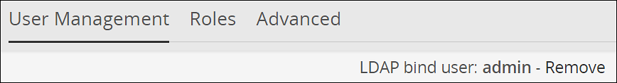
7.1.2 - Importing users to internal LDAP
Describes the procedure to import users to internal LDAP
In the User Management screen, you can import users from an external LDAP to the internal LDAP. This option gives you the flexibility to add selected users from your LDAP to the ESA.
Ensure that Proxy Authentication is enabled before importing users from an external directory service.
For more information about working with Proxy Authentication, refer to here.
The username in local LDAP is case-sensitive and the username in Active Directory is case-insensitive. It is recommended not to import users from external LDAP where the username in the local LDAP and the username in the external LDAP are same.
The users imported are not local users of the internal LDAP. You cannot apply password policy to these users. To convert the imported user to a local user, navigate to Settings > Users > User Management, select the user, and then click Convert to Local user ![]() . When you convert a user to a local LDAP user, ESA creates the user in its local LDAP server.
. When you convert a user to a local LDAP user, ESA creates the user in its local LDAP server.
Perform the following steps to import users to internal LDAP.
In the Web UI, navigate to Settings> Users > User Management.
Click Import Users to add an external LDAP user to the internal LDAP.The Import Users screen appears.
Select Search by Username to search the users by username or select Search by custom filter to search the users using the LDAP filter.
Type the required number of results to display in the Display Number of Results text box.
If you want to overwrite existing user, click Overwrite Existing Users.
Click Next.The users matching the search criteria appear on the screen.
Select the required users and click Next.The screen to select the roles appears.
Select the required roles for the selected users and click Next.
The Enter your password prompt appears. Enter the password and click Ok. If the number of unsuccessful password attempts exceed the defined value in the password policy, the account gets locked.
For more information about Password Policy, refer here.
The screen displaying the roles imported appears.
The users, along with the roles, are imported to the internal LDAP.
7.1.3 - Password policy configuration
Describes the procedure to import users to internal LDAP
The user with administrative privileges can define password policy rules. PolicyUser and ProxyUser have the Password Policy option as disabled, by default.
Defining a Password Policy
If the number of unsuccessful password attempts exceed the defined value in the password policy, the account gets locked.
For more information about Password Policy, refer here.
Perform the following steps to define a password policy.
From the ESA Web UI, navigate to Settings > Users.
On the User Management tab under the Define Password Policy area, click Edit (
 ).
).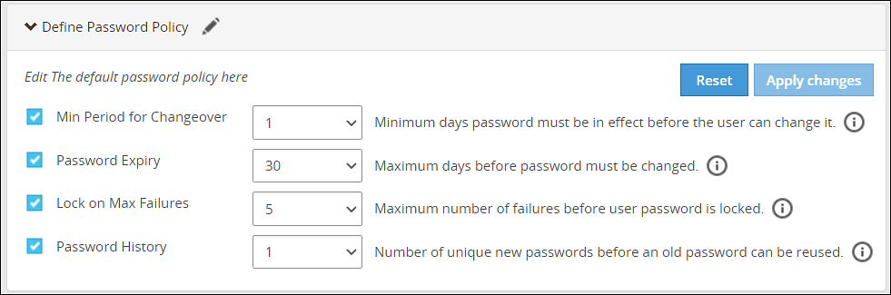
Select the password policy options for users which is described in the following table:
Password Policy Option Description Default Value Possible Values Minimum period for changeover Number of days since the last password change. 1 0-29 Password expiry Number of days a password remains valid. 30 0-720 Lock on maximum failures Number of attempts a user makes before the account is locked and requires Admin help for unlocking. 5 0-10 Password history Number of older passwords that are retained and checked against when a password is updated. 1 0-64 Click on Apply Changes.
Enter your password prompt appears. Enter the password and click Ok.
Resetting the password policy to default settings
If the number of unsuccessful password attempts exceed the defined value in the password policy, the account gets locked.
For more information about Password Policy, refer here.
The password policy is set to default values as mentioned in the Password Policy Configuration table.
The users imported into LDAP have Password Policy disabled, by default. This option cannot be enabled for imported users.
Perform the following steps to reset the password policy to default settings.
Click Reset.A confirmation message appears.
Click Yes.
The Enter your password prompt appears. Enter the password and click Ok.
Enabling password policy for Local LDAP users
Perform the following steps to enable password policy for Local LDAP users.
From the ESA Web UI, navigate to Settings > Users.
In the Manage Users area, click Password Policy toggle for the user.A dialog box appears requesting LDAP credentials.
The Enter your password prompt appears. Enter the password and click Ok.
After successful validation, password policy is enabled for the user.
Users locked out from too many password failures
If the number of unsuccessful password attempts exceed the defined value in the password policy, the account gets locked. Users who have been locked out receive the error message “Login Failure: Account locked” when trying to log in. To unlock the user, a user with administrative privileges must reset their password.
When an Admin user is locked, the local_admin user can be used to unlock the Admin user from the CLI Manager. Note that the local_admin is not part of LDAP, so it cannot be locked. For more information about Password Policy, including resetting passwords, refer Password Policy.
7.1.4 - Edit users
Describes the procedure to edit users
For every change done for the user, the Enter your password prompt appears. Enter the password and click Ok.
Perform the following steps to edit the user.
Navigate to Settings > Users > User Management. Click on a User Name.
Under the General Info section, edit the Description.
Under the Password Policy section, toggle to enable or disable the Password Policy.
Under the Roles section, select role(s) from the list for the user.
Click Reset Password to reset password for the user.
Click the
 icon to delete the user.
Users locked out from too many password failures
If the number of unsuccessful password attempts exceed the defined value in the password policy, the account gets locked.
For more information about Password Policy, refer here.
7.2 - Managing Roles
Describes the instructions to manage roles
Roles are templates that include permissions and users can be assigned to one or more roles. Users in the appliance must be attached to a role.
The default roles packaged with ESA are as follows:
| Roles | Description | Permissions |
|---|---|---|
| Policy Proxy User | Allows a user to connect to DSG via SOAP/REST and access web services using Application Protector (AP). | Proxy-User |
| Policy User | Allows user to connect to DSG via SOAP/REST and perform security operations using Application Protector (AP). | Policy-User |
| Security Administrator Viewer | Role that can view the ESA Web UI, CLI, and reports. | Security Viewer, Appliance CLI Viewer, Appliance web viewer, Reports Viewer |
| Shell Accounts | Role who has direct SSH access to Appliance OS shell.Note: It is recommended that careful consideration is taken when assigning the Shell Accounts role and permission to a user.Ensure that if a user is assigned to the Shell Account role, no other role is linked to the same user. The user has no access to the Web UI or CLI, except when the user has password policy enabled and is required to change password through Web UI. | Shell (non-CLI) AccessNote: The user can access SSH directly if the permission is tied to this role. |
| Security Administrator | Role who is responsible for setting up data security using ESA policy management, which includes but is not limited to creating policy, managing policy, and deploying policy. | Security Officer, Reports Manager, Appliance Web Manager, Appliance CLI Administrator, Export Certificates, DPS Admin, Directory Manager, Export Keys, RLP Manager |
The capabilities of a role are defined by the permissions attached to the role. Though roles can be created, modified, or deleted from the appliance, permissions cannot be edited. The permissions that are available to map with a user and packaged with ESA as default permissions are as follows:
| Permissions | Description |
|---|---|
| Appliance CLI Administrator | Allows users to perform all operations available as part of ESA CLI Manager. |
| Appliance Web Manager | Allows user to perform all operations available as part of the ESA Web UI. |
| Audit Store Admin | Allows user to manage the Audit Store. |
| Can Create JWT Token | Allows user to create JWT token for communication. |
| Customer Business manager | Allows users to retrieve metering reports. |
| DPS Admin | Allows user to use the DPS admin tool on the protector node. |
| Export Certificates | Allows user to use download certificates from ESA. |
| Key Manager | Allows user to access the Key Management Web UI, rotate ERK or DSK, and modify ERK states. |
| Policy-User | Allows user to connect to Data Security Gateway (DSG) via REST and perform security operations using Application Protector (AP). |
| RLP Manager | Allows user to manage rules stored on Row-Level Security Administrator (ROLESA). Manage includes accessing, viewing, creating, etc. |
| Reports Viewer | Allows user to only view reports. |
| Security Viewer | Allows user to have read only access to policy management in the Appliance. |
| Appliance CLI Viewer | Allows user to login to the Appliance CLI as a viewer and view the appliance setup and configuration. |
| Appliance web viewer | Allows user to login to the Appliance web-interface as a viewer. |
| AWS Admin | Allows user to configure and access AWS tools if the AWS Cloud Utility product is installed. |
| Directory Manager | Allows user to manage the Appliance LDAP Directory Service. |
| Export Keys | Allows user to export keys from ESA. |
| Reports Manager | Allows user to manage reports and do functions related to reports. Manage includes accessing, viewing, creating, scheduling, etc. |
| Security Officer | Allows user to manage policy, keys, and do functions related to policy and key management. Manage includes accessing, viewing, creating, deploying, etc. |
| Shell (non-CLI) Access | Allows user to get direct access to the Appliance OS shell via SSH. It is recommended that careful consideration is taken when assigning the Shell Accounts role and permission to a user. Ensure that if a user is assigned to the Shell Account role, no other role is linked to the same user. |
| Export Resilient Package | Allows user to export package from the ESA by using the RPS API. |
| Can Create JWT Token | Allows user to create a Java Web Token (JWT) for user authentication. |
| ESA Admin | Allows user to perform operations on Audit Store Cluster Management. |
| Insight Admin | Allows to perform operations on Discover Web UI. |
| Proxy-User | Allows user to connect to DSG via REST and perform security operations using Application Protector (AP). |
| SSO Login | Allows user to login to the system using the Single Sign-On (SSO) mechanism. |
The ESA Roles web UI is as seen in the following image.
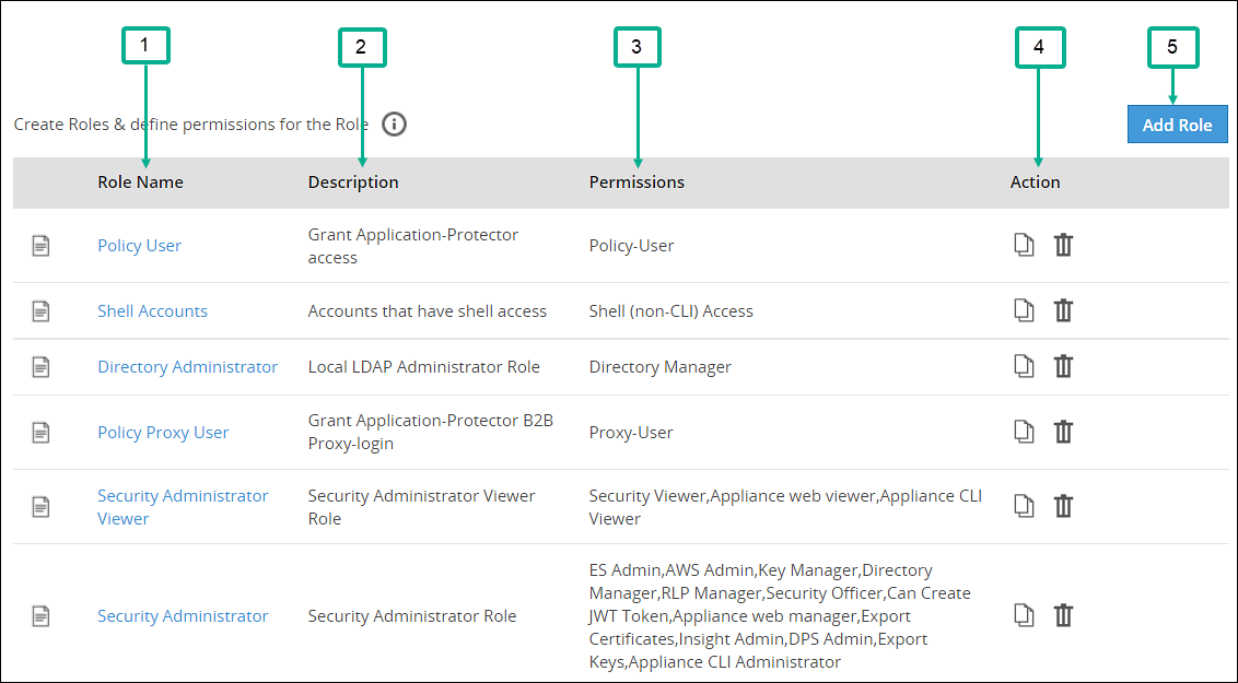
| Callout | Column | Description |
|---|---|---|
| 1 | Role Name | Name of the role available on ESA. Note: If you want to edit an existing role, click the role name from the displayed list. After making required edits, click Save to save the changes. |
| 2 | Description | Brief description about the role and its capabilities. |
| 3 | Permissions | Permission mapped to the role. The tasks that a user mapped to a role can perform is based on the permissions enabled. |
| 4 | Action | The following Actions are available.
|
| 5 | Add Role | Add a custom role to ESA. |
Duplicating and deleting roles
Keep the following in mind when duplicating and deleting roles.
- It is recommended to delete a role from the Web UI only. This ensures that the updates are reflected correctly across all the users that were associated with the role.
- When you duplicate or delete a role, the Enter your password prompt appears. Enter the password and click Ok to complete the task.
Adding a Role
You can create a custom business role with permissions and privileges that you want to map with that role. Custom templates provide the flexibility to create additional roles with ease.
Perform the following steps to add a role. In those steps we will use an example role named “Security Viewer”.
In the Web UI, navigate to Settings > Users > Roles.
If you want to edit an existing role, click the role name from the displayed list. After making required edits, click Save to save the changes.
Click Add Role to add a business role.
Enter Security Viewer as the Name.
Enter a brief description in the Description text box.
Select custom as the template from the Templates drop-down.
Under Role Permissions and Privileges area, select the permissions you want to grant to the role.Click Uncheck All to clear all the check boxes. Ensure that you do not select the Shell (non-CLI) Access permission for users who require Web UI and CLI access.
Click Save to save the role.
Enter your password prompt appears. Enter the password and click Ok.
7.3 - Configuring the proxy authentication settings
Describes the instructions to configure proxy authentication settings
To configure the proxy authentication from the Web UI, the directory_administrator permission must be associated with the required role. It is also possible to do this through the CLI manager. For more information about configuring LDAP from the CLI manager, refer to here.
Perform the following steps to configure proxy authentication settings.
In the Web UI, navigate to Settings > Users > Proxy Authentication. The following figure shows example LDAP configuration.

Enter the LDAP IP address for the external LDAP in LDAP URI.The accepted format is ldap://host:port.
- Click the
 icon to add multiple LDAP servers.
 - Click the
 icon to remove the LDAP server from the list.
- Click the
Enter data in the fields as shown in the following table:
Fields Description Base DN The LDAP Server Base distinguished name. For example: Base DN: dc=sherwood, dc=com. Bind DN Distinguished name of the LDAP Bind User.
It is recommended that this user is granted viewer permissions. For example: Bind DN: administrator@sherwood.comBind Password The password of the specified LDAP Bind User. StartTLS Method Set this value based on configuration at the customer LDAP. Verify Peer Enable this setting to validate the certificate from an AD. If this setting is enabled, ensure that the following points are considered: - You must require a CA certificate to verify the server certificate from AD.For more information about certificates, refer Certificate Management.
- The LDAP Uri matches the hostname in the server and CA certificates.
- LDAP AD URI hostname is resolved in the hosts file.
LDAP Filter Provide the attribute to be used for filtering users in the external LDAP. For example, you can use the default attribute, sAMAccountName, to authenticate users in a single AD.
Note: In case of same usernames across multiple ADs, it is recommended to use LDAP filter such as UserPrincipalName to authenticate users.Click Test to test the provided configuration.A LDAP test connectivity passed successfully message appears.
Click Apply to apply and save the configuration settings.
The Enter your password prompt appears. Enter the password and click Ok.A Proxy Authentication was ENABLED and configuration were saved successfully message appears.
Navigate to System > Services and verify that the Proxy Authentication Service is running.

If you make any changes to the existing configuration, click Save to save and apply the changes. Click Disable to disable the proxy authentication.
After the Proxy Authentication is enabled, the user egsyncd_service_admin is enabled. It is recommended not to change the password for this user.
After enabling Proxy Authentication, you can proceed to adding users and mapping roles to the users. For more information about importing users, refer here.
7.4 - Working with External Groups
Describes the instructions to work with external groups
The directory service providers, such as, Active Directory (AD) or Oracle Directory Server Enterprise Edition (ODSEE), are identity management systems that contain information about the enterprise users. You can map the users in the directory service providers to the various roles defined in the Appliances. The External Groups feature enables you to associate users or groups to the roles.
You can import users from a directory service to assign roles for performing various security and administrative operations in the appliances. Using External Groups, you connect to an external source, import the required users or groups, and assign the appliance-specific roles to them. The appliances automatically synchronize with the directory service provider at regular time intervals to update user information. If any user or group in a source directory service is updated, it is reflected across the users in the external groups. The updates made to the local LDAP do not affect the source directory service provider.
If any changes occur to the roles or users in the external groups, an audit event is triggered.
Ensure that Proxy Authentication is enabled to use an external group.
The following screen displays the External Groups screen.

Only users with Directory Manager role can configure the External Groups screen.
The following table describes the actions you can perform on the External Groups screen.
| Icon | Description |
|---|---|
| List the users present for the external group. | |
| Synchronize with the external group to update the users. | |
| Delete the external group. |
Required fields for External Groups
Listed below are the required fields for creating an External Group.
Title: Name designated to the External Group
Description: Additional text describing the External Group
Group DN: Distinguished name where groups can be found in the directory
Query by: To pull users from the directory server, query the directory server using required parameters. This can be achieved using one of the following two methods:
Query by UserQuery by User allows to add specific set of users from a directory server.
Group PropertiesIn the Group Properties, the search is based on the values entered in the Group DN and Member Attribute Name text boxes. Consider an example, where the values in the Group DN and Member Attribute Name are cn=esa,ou=groups,dc=sherwood,dc=com and memberOf respectively. In this case, the search is performed on every user that is available in the directory server. The memberOf value of the users are matched with the specified Group DN. Only those users whose memberOf value matches the Group DN values are returned.
Search FilterThis field facilitates searching multiple users using regex patterns. Consider an example, where the values in the Search Filter for the user is cn=S*. In this case all the users beginning with cn=S in the directory server are retrieved.
Query by GroupUsing this method, you can search and add users of a group in the directory server. All the users belonging to the group are retrieved in the search process.
Group PropertiesIn the Group Properties, the search is based on the values entered in the Group DN and Member Attribute Name text boxes. Consider an example, where the values in the Group DN and Member Attribute Name are cn=hr,ou=groups,dc=sherwood,dc=com and member respectively. The search is performed in the directory server for the group mentioned in the Group DN text box. If the group is available, then all the users of that group containing value of member attribute as cn=hr,ou=groups,dc=sherwood,dc=com are retrieved.
Search FilterThis field facilitates searching multiple groups across the directory server. The users are retrieved based on the values provided in the Search Filter and Member Attribute Name text boxes. A search is performed on the group mentioned in Search Filter and the value mentioned in the Member Attribute Name attribute of the group is fetched. Consider an example, where the values in the Search Filter for the group is cn=accounts and the value in the Member Attribute Name value is member. All the groups that match with cn=accounts are searched. The value that is available in the member attribute of those groups are retrieved as the search result.
Adding an External Group
You can add an external group to assign roles for a group of users. For example, consider a scenario to add an external group with data entered in the Search Filter textbox.
Perform the following steps to add an external group.
In the ESA Web UI, navigate to Settings > Users > External Groups.
Click Create.
Enter the required information in the Title and Description fields.

If you select Group Properties, then enter the Group DN and Member Attribute Name.For example,
Enter the following DN in the Group DN text box:
cn=Joe,ou=groups,dc=sherwood,dc=comEnter the following attribute in the Member Attribute Name text box:
memberOfThis text box is not applicable for ODSEE.
If you select Search Filter, enter the search criteria in the Search Filter text box.
For example,
For AD, you can enter the search filter as follows:
(&(memberOf=cn=John,dc=Bob,dc=com))For ODSEE, you can enter the search filter as follows:
isMemberOf=cn=Alex,ou=groups,dc=sherwood,dc=comClick Preview Users to view the list of users for the selected search criteria.
Select the required roles from the Roles tab.
Click Save.
An external group is added.
The Users tab is visible, displaying the list of users added as a part of the external group.
Importing from ODSEE and special characters
If you are importing users from ODSEE, usernames containing special characters are not supported. Special characters include semi colon, forward slash, curly brackets, parentheses, angled brackets, or plus sign. That is: ;, /, {}, () , <>, or +, respectively.
Editing an External Group
You can edit an external group to modify fields such as Description, Mode, Roles, or Group Properties. If any updates are made to the roles of the users in the external groups, the modifications are applicable immediately to the users existing in the local LDAP.
Ensure that you synchronize with the source directory service if you update the Group DN or the search filter.
Perform the following steps to edit an external group:
In the ESA Web UI, navigate to Settings > Users > External Groups.
Select the required external group.
Edit the required fields.
Click Save.
The Enter your password prompt appears. Enter the password and click Ok.The changes to the external group are updated.
Deleting an External Group
When you delete an external group, the following scenarios are considered while removing a user from an external group:
- If the users are not part of other external groups, the users are removed from the local LDAP.
- If the users are a part of multiple external groups, only the association with the deleted external group and roles is removed.
Perform the following steps to remove an External Group:
In the ESA Web UI, navigate to Settings > Users > External Groups.
Select the required external group and click the Delete (
) icon.The Enter your password prompt appears. Enter the password and click Ok.The external group is deleted.
Synchronizing the External Group
When the proxy authentication is enabled, the External Groups Sync Service is started. This service is responsible for the automatic synchronization of the external groups with the directory services. The time interval for automatic synchronization is 24 hours.
You can manually synchronize the external groups with the directory services using the Synchronize (![]() ) icon.
) icon.
After clicking theSynchronize (![]() ) icon, the Enter your password prompt appears. Enter the password and click Ok.
) icon, the Enter your password prompt appears. Enter the password and click Ok.
The following scenarios occur when synchronization is performed between the external groups and the directory services.
- Users are added to ESA and roles are assigned.
- Roles of existing users in ESA are updated.
- Users are deleted from the ESA if they are associated with any external groups.
Based on the scenarios, the messages appearing in the Web UI, when synchronization is performed, are described in the following table.
| Message | Description |
|---|---|
| Added | Users are added to the ESA the roles mentioned in the external groups are assigned to the user. |
| Updated | Roles pertaining to the users are updated ESA. |
| Removed | Roles corresponding to the deleted external group is removed for the users. Users are not deleted from ESA. |
| Deleted | Users are deleted from ESA as they are not associated to any external group. |
| Failed | Updates to the user fail. The reason for the failure in update appears in the Web UI. |
If a GroupDN for an external group is not available during synchronization, the users are removed or deleted. The following log appears in the Insight logs:
Appliance Warning: GroupDN is missing in external Source.
Also, in the Appliance logs, the following message appears:
External Group: <Group name>, GroupDN: <domain name> could not be found on the external source
7.5 - Configuring the Azure AD Settings
Describes the instructions to configure the Azure AD settings
You can configure the Azure AD settings from the Web UI. Using the Web UI, you can enable the Azure AD settings to manage user access to cloud applications, import users or groups, and assign specific roles to them.
For more information about configuring Azure AD Settings from the CLI Manager, refer here.
Before configuring Azure AD Settings on the ESA, you must have the following information that is required to connect the ESA with the Azure AD:
- Tenant ID
- Client ID
- Client Secret or Thumbprint
For more information about the Tenant ID, Client ID, Authentication Type, and Client Secret/Thumbprint, search for the text Register an app with Azure Active Directory on Microsoft’s Technical Documentation site at https://learn.microsoft.com/en-us/docs/
The following are the list of the API permissions that must be granted.
- Group.Read.All
- GroupMember.Read.All
- User.Read
- User.Read.All
To assign API permissions in Microsoft Azure, contact your Microsoft Azure administrator.
For more information about configuring the application permissions in the Azure AD, please refer https://learn.microsoft.com/en-us/graph/auth-v2-service?tabs=http.
Ensure that the Allow public client flows setting is Enabled. To enable the Allow public client flows setting, navigate to Authentication > Advanced settings, click the toggle button, and select Yes.
Perform the following steps to configure Azure AD settings:
- On the Web UI, navigate to Settings > Users > Azure AD.The following figure shows an example of Azure AD configuration.

Enter the data in the fields as shown in the following table:
Setting Description Tenant ID Unique identifier of the Azure AD instance. Client ID Unique identifier of an application created in Azure AD. Auth Type Select one of the Auth Type: - SECRET indicates a password-based authentication. In this authentication type, the secrets are symmetric keys, which the client and the server must know.
- CERT indicates a certificate-based authentication. In this authentication type, the certificates are the private keys, which the client uses. The server validates this certificate using the public key.
Client Secret/Thumbprint The client secret/thumbprint is the password of the Azure AD application. - If the Auth Type selected is SECRET, then enter Client Secret.
- If the Auth type selected is CERT, then enter Client Thumbprint.
For more information about the Tenant ID, Client ID, Authentication Type, and Client Secret/Thumbprint, search for the text Register an app with Azure Active Directory on Microsoft’s Technical Documentation site at https://learn.microsoft.com/en-us/docs/.
Click Test to test the provided configuration.The Azure AD settings are authenticated successfully. To save the changes, click ‘Apply/Save’. message appears.
Click Apply to apply and save the configuration settings.The Azure AD settings are saved successfully message appears.
7.5.1 - Importing Azure AD Users
Describes the instructions to import the Azure AD users
Before importing Azure users, ensure that the following prerequisites are considered:
- Ensure that the user is not present in the nested group. If the user is present in the nested group, then the nested group will not be synced on the ESA.
- Check the user status before importing them to the ESA. If a user with the Disabled status is imported, then that user will not be able to login to the ESA.
- Ensure that an external user is not added to the group. If an external user is added to the group, then that user will not be synced on the ESA.
- Ensure that the special character # (hash) is not used while creating the username. If you are importing users from the Azure AD, then the usernames containing the special character # (hash) will not be able to login to the ESA. The usernames containing the following special characters are supported in the ESA.
- ’ (single quote)
- . (period)
- ^ (caret)
- ! (exclamation)
- ~ (tilde)
- - (minus)
- _ (underscore)
- Ensure that the Azure AD settings are enabled before importing the users.
You can import users from the Azure AD to the ESA, on the User Management screen.
For more information about configuring the Azure AD settings, refer here.
Perform the following steps to import Azure AD users.
On the Web UI, navigate to Settings > Users > User Management.
Click Import Azure Users.
The Enter your password prompt appears. Enter the password and click Ok.The Import Users screen appears.
Search a user by entering the name in the Username/Filter box.
If required, toggle the Overwrite Existing Users option to ON to overwrite users that are already imported to the ESA.
Click Next.The users matching the search criteria appear on the screen.
Select the required users and click Next.The screen to select the roles appears.
Select the required roles for the selected users and click Next.The screen displaying the imported users appears.
Click Close.The users, with their roles, are imported to the ESA.
7.5.2 - Working with External Azure Groups
Describes the instructions to work with the external Azure groups
The Azure AD is an identity management system that contains information about the enterprise users. You can map the users in the Azure AD to the various roles defined in the ESA. The External Azure Groups feature enables you to associate users or groups to the roles.
You can import users from the Azure AD to assign roles for performing various security and administrative operations on the ESA. Using External Azure Groups, you connect to Azure AD, import the required users or groups, and assign the appliance-specific roles to them.
Ensure that Azure AD is enabled to use external Azure group.
The following screen displays the External Azure Groups screen.

Only users with the Directory Manager permissions can configure the External Groups screen.
The following table describes the actions that you can perform on the External Groups screen.
| Icon | Description |
|---|---|
| List the users present for the Azure External Group. | |
| Synchronize with the Azure External Group to update the users. | |
| Delete the Azure External Group. |
Adding an Azure External Group
You can add an Azure External Group to assign roles for a group of users.
Perform the following steps to add an External Group.
From the ESA Web UI, navigate to Settings > Users > Azure External Groups.
Click Add External Group.
Enter the group name in the Groupname/Filter field.

Click Search Groups to view the list of groups.
Select one group from the list, and click Submit.
Enter a description in the Description field.
Select the required roles from the Roles tab.
Click Save.The External Group has been created successfully message appears.
Editing an Azure External Group
You can edit an Azure external group to modify Description and Roles. If any updates are made to the roles of the users in the Azure External Groups, then the modifications are applicable immediately to the users existing on the ESA.
Perform the following steps to edit an External Group:
On the ESA Web UI, navigate to Settings > Users > Azure External Groups.
Select the required external group.
Edit the required fields.
Click Save.
The Enter your password prompt appears. Enter the password and click Ok.The changes to the external group are updated.
Synchronizing the Azure External Groups
When the Azure AD is enabled, the Azure External Groups is started. You can manually synchronize the Azure External Groups using the Synchronize (![]() ) icon.
) icon.
After clicking the Synchronize (![]() ) icon, the Enter your password prompt appears. Enter the password and click Ok.
) icon, the Enter your password prompt appears. Enter the password and click Ok.
Note: If the number of unsuccessful password attempts exceed the defined value in the password policy, then the user account gets locked.
For more information about Password Policy, refer here.
The messages appearing on the Web UI, when synchronization is performed between Azure External Groups and the ESA, are described in the following table.
| Message | Description |
|---|---|
| Success |
|
| Failed | Updates to the user failed.Note: The reason for the failure in updating the user appears on the Web UI. |
Deleting Azure External Groups
When you delete an Azure External Group, the following scenarios are considered while removing a user from the Azure External Group:
- If the users are not part of other external groups, then the users are removed from the ESA.
- If the users are a part of multiple external groups, the only the association with the deleted Azure External Group and roles is removed.
Perform the following steps to remove an Azure External Group.
From the ESA Web UI, navigate to Settings > Users > Azure External Groups.
Select the required external group and click the Delete (
) icon.The Enter your password prompt appears. Enter the password and click Ok.The Azure External Group is deleted.