The Settings menu on the ESA Web UI allows you to configure various features, such as, antivirus, two-factor authentication, networking, file management, user management, and licences.
This is the multi-page printable view of this section. Click here to print.
Working with Settings
Describes the settings which can be configured using the ESA Web UI
- 1: Working with Antivirus
- 1.1: Customizing Antivirus Scan Options
- 1.2: Scheduling Antivirus Scan
- 1.3: Updating the Antivirus Database
- 1.4: Working with Antivirus Logs
- 2: Configuring Appliance Two Factor Authentication
- 2.1: Working with Automatic Per-User Shared-Secret
- 2.2: Working with Host-Based Shared-Secret
- 2.3: Working with Remote Authentication Dial-up Service (RADIUS) Authentication
- 2.4: Working with Shared-Secret Lifecycle
- 2.5: Logging in Using Appliance Two Factor Authentication
- 2.6: Disabling Appliance Two Factor Authentication
- 3: Working with Configuration Files
- 4: Working with File Integrity
- 5: Managing File Uploads
- 6: Configuring Date and Time
- 7: Configuring Email
- 8: Configuring Network Settings
- 8.1: Managing Network Interfaces
- 8.2: NIC Bonding
- 9: Configuring Web Settings
- 9.1: General Settings
- 9.2: Session Management
- 9.3: Shell in a box settings
- 9.4: SSL cipher settings
- 9.5: Updating a protocol from the ESA Web UI
- 10: Working with Secure Shell (SSH) Keys
1 - Working with Antivirus
Describes the operations which can be performed using the AntiVirus option
The Antivirus program uses ClamAV, an open source and cross-platform Antivirus engine designed to detect malicious Trojan, virus, and malware threats. A single file or directory, or the whole system can be scanned. Infected file or files are logged and can be deleted or moved to a different location, as required.
You can use Antivirus to perform the following functions:
- Schedule the scans or run these on demand.
- Update the virus data signature or database files, or run the update on demand.
- View the logs generated for every virus found.
Simple user interfaces and standard configurations for both Web UI and CLI of the Appliance make viewing logs, running scans, or updating the virus signature file easy.
FIPS mode and Antivirus
If the FIPS mode is enabled, then the Antivirus is disabled on the appliance.

For more information on the FIPS Mode, refer here.
1.1 - Customizing Antivirus Scan Options
Describes the procedure to customize an Antivirus scan
In the Antivirus section, you can customize the scan by setting the following options:
- Action: Ignore the scan result, move the file to a separate directory, or delete the infected files
- Recursive: Implement and scan directories, sub-directories, and files
- Scan Directory: Specify the directory
To customize Antivirus scan options:
Navigate to Settings > Security > Antivirus.
Click Options.
Choose the required options and click Apply.A message
Option changes are accepted!appears.
1.2 - Scheduling Antivirus Scan
Describes the procedure to schedule an Antivirus scan
An Antivirus scan can be scheduled only from the Web UI.
Navigate to System > Task Scheduler.
Search Anti-Virus system scan.If it is present, then scanning is already scheduled.Verify the Frequency and update if required.
If Antivirus system scan is not present, then follow these steps:
a. Click +New Task.
b. Add the details, such as the Name, Description, and Frequency.
c. Add the command line steps, and Logging details.
Click Save at the top right of the window.
The Antivirus scanning automatically begins at the scheduled time and logs are saved.
1.3 - Updating the Antivirus Database
Describes the procedure to update the Antivirus database
You must update the Antivirus database or the signature files frequently. This ensures the Antivirus is updated so it can pick up any new threats to the appliance. The Antivirus database can either be updated from the official ClamAV website, local websites, mirrors, or using the signature files. The signature files are downloaded from the website and uploaded on the ESA Web UI. The following are the Antivirus signature database files that must be downloaded:
- main.cvd
- daily.cvd
- bytecode.cvd
The Antivirus signature database files can be updated in one of the following two ways:
- SSH/HTTP/HTTPS/FTP
- Official website/mirror/local sites
It is recommended that you update the signature database files directly from the official website.
Updating the Antivirus Database Manually
Perform the following steps to update the Antivirus database.
On the ESA Web UI, navigate to Settings > Security > Antivirus.
Click Database Update > Settings.
Select one of the following settings.
| Settings | Description |
|---|---|
| Local/remote mirror server | Server containing the database update. Enter the URL of the server in Input the target URL text box. |
| Official website through HTTP proxy server | Proxy server of ClamAV containing the database update. Enter the following information: |
| Local directory | Local directory where the updated database signature files, such as, main.cvd, daily.cvd and bytecode.cvd are stored. Enter the directory path in Input the target directory text box. |
| Remote host | Host containing the updated database signature files. Connect to this host using an SSH, HTTP, HTTPS, or FTP connection. Enter information in the required fields to establish a connection with the remote host. |
- Select Confirm.The database update is initiated.
Updating the Antivirus Signature Files Manually
In case network is not available or the Internet is disconnected, you can manually update the signature database files. The signature files are downloaded from the website and placed in a local directory. The following are the Antivirus signature database files that must be downloaded:
- main.cvd
- daily.cvd
- bytecode.cvd
It is recommended that you update the signature database files directly from the official website.
Perform the following steps to manually update the Antivirus database signature files.
Download the Antivirus signature database files: main.cvd, daily.cvd, and bytecode.cvd.
On the CLI Manager, navigate to Administration > OS Console.
Create the following directory in the appliance:
/home/admin/clam_update/Save the downloaded signature database files in the /home/admin/clam_update/ directory.
Scheduling Update of Antivirus Signature Files
Scheduling an update option is available only on the Web UI.
Go to System > Task Scheduler.
Select the Anti-Virus database update row.
Click Edit from the Scheduler task bar.For more information about scheduling appliance tasks, refer here.
Click Save at the top right corner of the workspace window.
1.4 - Working with Antivirus Logs
Describes the procedure to work with Antivirus logs
Log files are generated for all system and database activities. These logs are stored in the local log
file, runtime.log which is saved in the /etc/opt/Antivirus/ directory.
You can view and delete the local log files.
Viewing Antivirus Logs
The logs for the Antivirus can be viewed from the ESA Web UI. The logs consist of Antivirus database updates, scan results, infections found, and so on. These logs are also available on the Audit Store > Dashboard > Discover screen. You can view all logs, including those deleted, in the local file.
Perform the following steps to view logs.
- Navigate to Settings > Security > Antivirus.
- Click Log.
Deleting Logs from Local File Using the Web UI
Perform the following steps to delete logs from local file using the Web UI.
- Navigate to Settings > Security > Antivirus.
- Click Log.
- Click Purge.All existing logs in the local log file are deleted.
Viewing Logs from the CLI Manager
Perform the following steps to delete logs from local file using the CLI Manager.
- Navigate to Status and Logs > Appliance Logs.
- Select System event logs.
- Press View.
- From the list of available installed patches, select patches.
- Press Show.A detailed list of patch related logs are displayed on the ESA Server window.
Configuring Log Rotation and Log Retention
Perform the following steps to configure log rotation and log retention.
Append the following configuration to the /etc/logrotate.conf file:
/var/log/clamav/*.log
{ missingok monthly size 10M rotate 1 }
For periodic log rotation, run the following command:
cd /etc/opt/Antivirus/
mv /etc/opt/Antivirus/runtime.log /var/log/clamav
ln -s /var/log/clamav/runtime.log runtime.log
2 - Configuring Appliance Two Factor Authentication
Describes the procedure to configure two factor authentication settings
Two factor authentication is a verification process where two recognized factors are used to identify you before granting you access to a system or website. In addition to your password, you must correctly enter a different numeric one-time passcode or the verification code to finish the login process. This provides an extra layer of security to the traditional authentication method.
In order to provide this functionality, a trust is created between the appliance and the mobile device being used for authentication. The trust is simply a shared-secret or a graphic barcode that is generated by the system and is presented to the user upon first login.
There is an advantage of using the two-factor authentication feature. If a hacker manages to guess your password, then entry to your system is not possible. This is because a device is required to generate the verification code.
The verification code is a dynamic code that is generated by any smart device such as smartphone or tablet. The user enters the shared-secret or scans the barcode into the smart device, and from that moment onwards the smartphone generates a new verification-code every 30-60 seconds. The user is required to enter this verification code every time as part of the login process. For validating the one time password (OTP), ensure that the date and time on the ESA and your system are in sync.
Protegrity appliances and authenticators
There are a few requirements for using two factor authentication with Protegrity appliances.
- For validating one time passwords (OTP), the date and time on the ESA and the validating device must be in sync.
- Protegrity appliances only support use of the Google, Microsoft, or Radius Authenticator apps.
- Download the appropriate app on a mobile device, or any other TOTP-compatable device or application.
The Security Officer configures the Appliance Two Factor Authentication by any one of the following three methods:
Automatic per-user shared-secret is the default and recommended method. It allows having a separate shared-secret for each user, which is generated by the system for them. The shared-secret will be presented to the user upon the first login.
Radius Authentication is the authentication using the RADIUS protocol.
Host-based shared-secret allows a common shared-secret for all users, which can be specified and distributed to the users by the Security Officer. Host-based shared-secret method is useful to force the same secret code for multiple appliances in clustered environments.
2.1 - Working with Automatic Per-User Shared-Secret
Describes the procedure to Automatic Per-User Shared-Secret
Automatic per-user shared-secret is the default and recommended method for configuring two factor authentication. It allows having a separate shared-secret for each user, which is generated by the system for them. The shared-secret will be presented to the user upon the first login.
Configuring Two Factor Authentication with Automatic Per-User Shared-Secret
The following section describes how to configure two factor authentication using automatic per-user shared-secret.
Perform the following steps to configure two factor authentication with automatic per-user shared-secret.
From the ESA Web UI, navigate to Settings > Security > Two Factor Authentication.
Check the Enable Two-Factor-Authentication check box.
Select the Automatic per-user shared-secret option.
The following pane appears with the options to enable this authentication mode.

If required, then you can customize the message that will be presented to users upon their first login.
Check the Advanced Settings check box to display the Console Message button. By clicking Console Message, a new window appears where you can review and modify the message that will be presented to the user.

You can apply the following logging-settings in order to specify what to log:
- Log failed log-in attempts
- Log any successful log-ins
- Log only first-successful log-in
Click Apply to save the changes.
Logging in to the Web UI
Before beginning, be aware of time limits. When entering codes from the authenticator there is a time limit. Ensure codes are entered in the Enter Authentication code field within the displayed time limit.
The following section describes how to log in to the Web UI after configuring automatic per-user shared-secret.
Perform the following steps to login to the Web UI:
Navigate to the ESA Web UI login page.
In the Username and Password text boxes, enter the user credentials.
Click Sign in.The Two step authentication screen appears.

Scan the QR code using an authentication application.Alternatively, click the Can’t see QR code? link.A QR code gets generated and displayed below it as shown in the figure.

Enter the displayed code in the authentication app to generate One-time password.
In the Enter authentication code field box, enter the one-time password, and click Verify.
After the code is validated, the ESA home page appears.
2.2 - Working with Host-Based Shared-Secret
Describes the procedure to Host-Based Shared-Secret
Host-based shared-secret allows a common shared-secret for all users, which can be specified and distributed to the users by the Security Officer. Host-based shared-secret method is useful to force the same secret code for multiple appliances in clustered environments.
Configuring Two Factor Authentication with Host-Based Shared-Secret
The following section describes how to configure two factor authentication using host-based shared-secret.
Perform the following steps to configure Two Factor Authentication with Host-based shared-secret.
- On the ESA Web UI, navigate to Settings > Security > Two Factor Authentication.
- Check the Enable Two-Factor-Authentication check box.
- Select Host-based shared-secret from Authentication Mode.
- Click Modify.The Host-based shared-secret key appears.
If required, click Generate to modify the Host-based shared-secret key. Ensure that you note the Host-based shared-secret key to generate TOTP. - You can apply the following logging-settings in order to specify what to log:
- Log failed log-in attempts
- Log any successful log-ins
- Click Apply to save the changes. A confirmation message appears.
Logging in to the Web UI
Before beginning, be aware of time limits. When entering codes from the authenticator there is a time limit. Ensure codes are entered in the authenticator code box within the displayed time limit
The following section describes how to log in to the Web UI after configuring host-based shared-secret.
To login to the Web UI:
Navigate to the ESA Web UI login page.
In the Username and Password text boxes, enter the user credentials.
Click Sign in.
The 2 step authentication screen appears.

Use the Host-Based Shared-Secret key obtained from the configuration process to generate authentication code.
Enter the Host-Based Shared-Secret key in the authentication app to generate authentication code.
In the authenticator code box, enter the authentication code, and click Verify.
After the code is validated, the ESA home page appears.
2.3 - Working with Remote Authentication Dial-up Service (RADIUS) Authentication
Describes the procedure work with RADIUS Authentication
The Remote Authentication Dial-up Service (RADIUS) is a networking protocol for managing authentication, authorization, and accounting in a network. It defines a workflow for communication of information between the resources and services in a network. The RADIUS protocol uses the UDP transport layer for communication. The RADIUS protocol consists of two components, the RADIUS server and the RADIUS client. The server receives the authentication and authorization requests of users from the RADIUS clients. The communication between the RADIUS client and RADIUS server is authenticated using a shared secret key.
You can integrate the RADIUS protocol with an ESA for two-factor authentication. The following figure describes the implementation between ESA and the RADIUS server.

- The ESA is connected to the AD that contains user information.
- The ESA is a client to the RADIUS sever that contains the network and connection policies for the AD users. It also contains a RADIUS secret key to connect to the RADIUS server. The communication between the ESA and the RADIUS sever is through the Password Authentication Protocol (PAP).
- An OTP generator is configured with the RADIUS server. An OTP is generated for each user. Based on the secret key for each user, an OTP for the user is generated.
In ESA, the following two files are created as part of the RADIUS configuration:
- The dictionary file that contains the default list of attributes for the RADIUS server.
- The custom_attributes.json file that contains the customized list of attributes that you can provide to the RADIUS server.
Important : When assigning a role to the user, ensure that the Can Create JWT Token permission is assigned to the role.If the Can Create JWT Token permission is unassigned to the role of the required user, then remote authentication fails.To verify the Can Create JWT Token permission, from the ESA Web UI navigate to Settings > Users > Roles.
Configuring Radius Two-Factor Authentication
To configure Radius two-factor authentication:
On the ESA Web UI, navigate to Settings > Security > Two Factor Authentication.
Check the Enable Two-Factor-Authentication checkbox.
Select the Radius Server option as shown in the following figure.
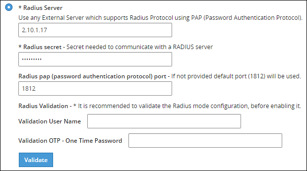
Type the IP address or the hostname of the RADIUS server in the Radius Server text box.
Type the secret key in the Radius Secret text box.
Type the port of the RADIUS server in the Radius port text box.Alternatively, the default port is 1812.
Type the username that connects to the RADIUS server in the Validation User Name text box.
Type the OTP code for the user in the Validation OTP text box.
Click Validate to validate the configuration.A message confirming the configuration appears.
Click Apply to apply the changes.
Logging in to the Web UI
Perform the following steps to login to the Web UI:
Open the ESA login page.
Type the user credentials in the Username and Password text boxes.
Click Sign-in.The following screen appears.
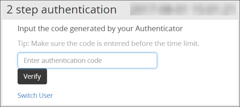
Type the OTP code and select Verify.After the OTP is validated, the ESA home page appears.
Editing the Radius Configuration Files
To edit the configuration files:
On the ESA Web UI, navigate to Settings > System.
Under OS-Radius Server tab, click Edit corresponding to the custom_attibutes.json or directory to edit the attributes.
If required, modify the attributes to the required values.
Click Save.The changes are saved.
Logging in to the CLI
Perform the following steps to login to CLI Manager:
Open the ESA CLI Manager.
Enter the user credentials.
Press ENTER .The following screen appears.
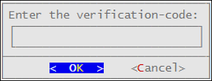
Type the verification code and select OK.After the code is validated, the main screen for the CLI Manager appears.
2.4 - Working with Shared-Secret Lifecycle
Describes the procedure work with shared-secret lifecycle
All users of appliance two factor authentication get a shared-secret for verification. This shared-secret for a user remains in the two factor authentication group list until it is manually deleted. Even if a user becomes ineligible to access the system, the username remains linked to the shared-secret.
This exception is valid for those users opting for per-user authentication.
If the same user or another user with the same name is again added to the system, then the user becomes eligible to use the already existing shared-secret.
To prevent this exception, ensure that an ineligible user is manually removed from the Two Factor Authentication group.
Revoking Shared-Secret for the User
The option to revoke shared-secret is useful when user needs to switch to another mobile device or the previous shared-secret cannot be retrieved from the earlier device.
Perform the following steps to revoke shared-secret for the user:
On the ESA Web UI, navigate to Settings > Security > Two Factor Authentication.
Ensure that the Enable Two-Factor-Authentication and Automatic per-user shared-secret checkbox are checked.
Inspect Users Shared Secrets area to identify user account to revoke.You can revoke users who have already logged in to the Appliance.
Click Revoke.
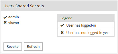
Select the user to discard by clicking the checkbox next to the username.
Click Apply to save the changes.A new shared-secret code will be created for the revoked user and is presented upon the next login.
2.5 - Logging in Using Appliance Two Factor Authentication
Describes the procedure to log in using the Two Factor Authentication
Perform the following steps to log in using Appliance Two Factor Authentication:
Navigate to ESA login page.
Enter your username.
Enter your password.
Click Sign in.After verification, a separate login dialog appears.

As a prerequisite, a new user must setup an account on Google Authenticator. Download the Google Authenticator app in your device and follow the instructions to create a new account.
Enter the shared-secret in your device.If the system is configured for per-user shared-secret, then this secret code is made available. If this is a web-session, then you are presented with a barcode and the applications that support it.
After you accept the shared-secret, the device displays a verification code.
Enter this verification code in the screen displayed in step 4.
Click Verify.
2.6 - Disabling Appliance Two Factor Authentication
Describes the procedure to disable the Two Factor Authentication
Perform the following steps to disable Two Factor Authentication:
Using the ESA Web UI, navigate to Settings > Security > Two Factor Authentication.
Clear the Enable Two-Factor-Authentication checkbox.
Click Apply to save the changes.
Disable Two Factor through local console
You can also disable two-factor authentication from the local console.You need to switch to OS console and execute the following command.
# /etc/opt/2FA/2fa.sh -–disable
3 - Working with Configuration Files
Describes the work with the configuration file
The Product Files screen displays the configuration files of all the products that are installed in ESA. You can view, modify, delete, upload, or download the configuration files from this screen. In the ESA Web UI, navigate to Settings > System > Files to view the configuration files.
The following table describes the different products and their respective configuration files that are available in ESA.
| Product | Configuration Files | Description |
| OS – Radius Server | Dictionary | Contains the dictionary translations for analyzing requests and generating responses for RADIUS server. |
| custom_attributes.json | Contains the configuration settings of the header data for the RADIUS server. | |
| OS –Export/Import | Customer.custom | Lists the custom files that can be exported or
imported. For more information about exporting custom files, refer here. |
| Audit Store-SMTP Config Files | smtp_config.json | Contains the SMTP configuration settings for sending email alerts. |
| smtp_config.json.example | Contains SMTP configuration settings and example values for sending email alerts. This is a template file. | |
| Policy Management – Member Source Service User Files | exampleusers.txt | Lists the users that can be used in policy. For more
information about policy users, refer Policy Management. |
| Policy Management – Member Source Service Group Files | examplegroups.txt | Lists the user groups that can be used in policy. For
more information about policy user groups, refer Policy Management.
. |
| Settings → System → Files → Downloads - Other files | contractual.htm | Lists all the third-party software licenses that are
utilized in ESA.NoteYou cannot modify the file. |
| Distributed Filesystem File Protector – Configuration Files | dfscacherefresh.cfg | Contains the DFSFP configuration settings such as, logging,
SSL, Security, and so on. For more information about the
dfscacherefresh.cfg file, refer to the
Protegrity Big Data Protector Guide 9.2.0.0
.NoteStarting
from the Big Data Protector 7.2.0 release, the HDFS File Protector
(HDFSFP) is deprecated. The HDFSFP-related sections are retained
to ensure coverage for using an older version of Big Data
Protector with the ESA 7.2.0. |
| Cloud Gateway –Settings | gateway.json | Lists the log level settings for Data Security Gateway. For more information about the
gateway.json file, refer to the Protegrity Data Security Gateway User Guide
3.2.0.0. |
| alliance.conf | Configuration file to direct syslog events between servers over TCP or UDP. |
The following figure illustrates various actions that you can perform on the Product Files screen.
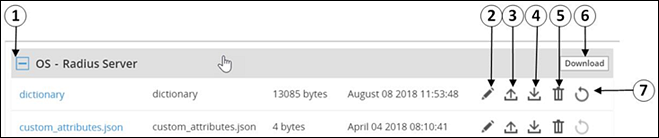
| Callout | Description | Action |
|---|---|---|
| 1 | Collapse/Expand | Collapse or expand to view the configuration files. |
| 2 | Edit | Edit the configuration file. |
| 3 | Upload | Upload a configuration file.Note: When you upload a file, it replaces the existing file in the system. |
| 4 | Download | Download the file to your local system. |
| 5 | Delete | Delete the file from the system. |
| 6 | Download | Download all the files of the product to your local system. |
| 7 | Reset | Reset the configuration to the previously saved settings. |
Viewing a Configuration File
You can view the contents of the configuration file from the Web UI. If the file size is greater than 5 MB, you must download the file to view the contents.
Perform the following steps to view a file:
Navigate to Settings > System > Files.The screen with the files appears.
Click on the required file. The contents of the file appear.
You can modify, download, or delete the file using the Edit, Download and Delete icon respectively.
Uploading a Configuration File
Configuration files can be uploaded using this option.For more information about the configuration files, refer Working with Configuration Files.
Perform the following steps to upload a file.
- Navigate to Settings > System > Files.The screen with the files appears.
- Click on the upload icon.The file browser icon appears.
- Select the configuration file and click Upload File.A confirmation message appears.
- Click Ok.A message confirming the upload appears.
Modifying a Configuration File
In addition to editing the file from the Files screen, you can also modify the content of the file from the view option. If you want to modify the content of a file whose size is greater than 5 MB, you must download the file to the local machine, modify the content, and then upload the file through the Web UI.
For instructions to download a configuration file, refer here.
Perform the following steps to modify a file.
- Navigate to Settings > System > Files.The screen with the files appears.
- Click on the required file.The contents of the file appear.
- Click the Edit to modify the file.
- Perform the required changes and click Save.A message confirming the changes appears.
Deleting a Configuration File
In addition to deleting the file from the Files screen, you can also delete the file from the view option. After you delete the file, an exclamation icon appears indicating that the file does not exist on the server. Using the reset functionality, you can restore the deleted file.
Perform the following steps to delete a file.
- Navigate to Settings > System > Files.The screen with the files appears.
- Click on the required file.The contents of the file appear.
- Click the Delete icon to modify the file.A message confirming the deletion appears.
- Select Yes.
Resetting a File
The Reset functionality is used to restore the changes that are done to your file. For every configuration file, the Reset icon is disabled. This icon is enabled when you perform any of the following changes:
- Modify the configuration file
- Delete the configuration file
When you modify or delete a file, the original file is backed up in the /etc/configuration-files-backup directory. For every modification, the file in the directory is overwritten. When you click the Reset icon, the file is retrieved from the directory and restored on the Files screen.
Perform the following steps to restore a file.
- Navigate to Settings > System > Files.The screen with the files appears.
- Click the Reset icon to restore a file.The file that is edited or deleted is restored.
Limits on resetting files
Only the changes that are performed on the files through the Web UI are backed up. Changes performed on the files through the CLI Manager are not backed up and cannot be restored.
4 - Working with File Integrity
Describes working with the file integrity option
The content modifications can be viewed by the Security Officer since the PCI specifications require that sensitive files and folders in the Appliance are monitored. This information contains password, certificate, and configuration files. The File Integrity Monitor makes a weekly check and all changes made to these files can be reviewed by authorized users.

To check file modifications at any given time, click Settings > Security > File Integrity > Check. The Security Officer views and accepts the changes, writing comments as necessary, in the comment box. Accepting changes means that the changes are removed from the viewable list. Changes cannot be rejected. You must not accept deletion of system files. These files must be available.
Only the last modification made to a file appears.
All the changes can also be viewed on the Audit Store > Dashboard > Discover screen. Another report shows all accepted changes. For more information about Discover, refer Discover.
Before applying a patch, it is recommended to check the files and accept the required changes under Settings > File Integrity > Check.
After installing the patches for appliances such as ESA or DSG, check the files and accept the required changes again under Settings > Security > File Integrity > Check.
5 - Managing File Uploads
Describes the procedure to manage file uploads
You can upload a patch file of any size from the File Upload screen in the ESA Web UI. The files uploaded from the Web UI are available in the /opt/products_uploads directory.
After the file is uploaded, in the Uploaded Files section, select the file to view the file information, download it, or delete it.
To upload a file:
Navigate to Settings > System > File Upload.The File Upload page appears.
In the File Selection section, click Choose File.The file upload dialog box appears.
Select the required file and click Open.
- You can only upload files with .pty and .tgz extensions.
- If the file uploaded exceeds the Max File Upload Size, then a password prompt appears. Only a user with the administrative role can perform this action. Enter the password and click Ok.
- By default, the Max File Upload Size value is set to 25 MB. To increase this value, refer here.
Click Upload.The file is uploaded to the
/opt/products_uploadslocation.- If a file contains spaces in its name, then it will be automatically replaced with underline character (_).
- The files are scanned by the internal AntiVirus before they are uploaded in the ESA.
- If the FIPS mode is enabled, then the anti-virus scan is skipped during the file upload.
- The SHA512 checksum value is validated during the upload process.
- If the network is interrupted while uploading the file, then the ESA retries to upload the file.The retry upload process is attempted ten times. Each attempt lasts for ten seconds.
After the file is uploaded successfully, then from the Uploaded Files area, choose the uploaded patch.The information for the selected patch appears.

Verifying uploaded file integrity
To verify the integrity of the uploaded file, validate the checksum values displayed on the screen with the checksum values of the downloaded patch file.You can obtain the checksum values from the My.Protegrity or contact Protegrity Support.
6 - Configuring Date and Time
Describes the procedure to configure date and time
You can use the Date/Time tab to change the date and time settings. To update the date and time, navigate to Settings > System > Date/Time.
The Date and Time screen with the Update Time Periodically option enabled is shown in the following figure.

The date and time options are described in the following table.
| Setting | Details | How to configure/change |
|---|---|---|
| Update Time Periodically | Synchronize the time with the specified NTP Server, upon boot and once an hour. | You can enable this option using Enable button and disable it using Disable. Only enable or disable NTP settings from the CLI Manager or the Web UI. |
| Current Appliance Date/Time | Manually synchronize the time with the specified NTP Server. You can use NTP Server synchronization only if NTP service is running. | You can force and restart time synchronization using Reset NTP Sync. You can display NTP analysis using NTP Query button. |
| Set Time Zone | Specify the time zone for your appliance. | Select your local time zone from the Set Time Zone list and click Set Time Zone. |
| Set Manually Date/Time (mm/dd/yyyy hh:mm) | Set the time manually. | Type the date and time using the format mm/dd/yyyy hh/mm. Click Set Date/Time.Note: The Set Manually Date/Time (mm/dd/yyyy hh:mm) text box appears only if the Update Time Periodically functionality is disabled. |
7 - Configuring Email
Describes the procedure to configure Email
The SMTP setting allows the system to send emails.

You can test that the email works by clicking Test. Error logs can be viewed on the Audit Store > Dashboard > Discover screen.
For more information about Discover, refer Working with Discover.
Some scripts run after you click Save.Ensure to save the details only when the connection is intact.

If the email address cannot be authenticated, then the Show Test Communication area displays the communication between the appliance and the SMTP server for debugging.
8 - Configuring Network Settings
Describes the procedure to configure the network settings
On the Network Settings screen, you can configure the network details for the ESA. The following table explains the different settings that can be configured.
Information in the following table is specific to the Web UI. For information on the same features and configuring them in the CLI, refer here.
| Setting | Details | How to configure/change |
|---|---|---|
| Hostname | The hostname is a unique name for a system or a node in a network.Ensure that the hostname does not contain the dot(.) special character. | Click Apply on the Web UI or change the hostname of the appliance from the Network Settings screen in the CLI Manager. |
| Management IP | The management IP, which is the IP address of the appliance, is defined through CLI Manager. | Select Blink to identify the interface. This will cause a LED on the NIC to blink and then click Change. |
| Default Route | The default route is an optional destination for all network traffic that does not belong to the LAN segment. For example, the IP address of your LAN router in the IP address format is 172.16.8.12. It is required only if the appliance is on a different subnet than the Appliance Web Interface. | Click Apply to set the default route. |
| Domain | The appliance domain name specified during appliance installation. | You can change it by specifying a new name and clicking Apply. |
| Search Domains | The appliance can belong to one domain and search an additional three domains. | You can add them using Add button. |
| Domain Name Servers | If your appliance uses domain names and IP addresses, then you must configure a domain name server (DNS) to help resolve Internet name addresses. The domain name should be for your local network, like Protegrity.com or math.mit.edu and the name servers should be IP addresses. The appliance can use up to three DNS servers for name resolving. Once you have configured a DNS, the system can be managed using an SSH connection. | You can add them using Add button, and remove them using Remove. You can specify them using Apply button. |
8.1 - Managing Network Interfaces
Describes the procedure to manage the network interfaces
Using Settings > Network > Network Settings, you can view appliance network interfaces names and addresses and add them from the Interfaces page.

Changes to IP addresses
Changes to IP addresses are immediate. Changes to the management IP (on ethMNG), while connected via SSH or the Appliance Web Interface, causes the session to disconnect.
Assigning an Address to an Interface
Perform the following steps to assign an address to an interface.
- Navigate to Settings > Network.
- Click Network Settings.The Interfaces page appears.
- Identify the interface on the appliance by clicking Blink for the interface you want to identify.Select a LED on the NIC that blinks to indicate that interface.
- In the Interface row, type the address and Net mask of the interface, and then click Add.
Assigning an Address to an Interface Using Web UI
Perform the following steps to assign an address to an interface.
- In the Web UI, navigate to Settings > Network > Network Settings.The Network Settings page appears.
- In the Network Interfaces area, select Add New IP in the Gateway column.
Ensure that the IP address for the NIC is added. - Enter the IP address of the default gateway and select OK.The default gateway for the interface is added.
8.2 - NIC Bonding
Describes the procedure to manage the NIC interfaces
The Network Interface Card (NIC) is a device through which appliances, such as ESA or DSG, on a network connect to each other. If the NIC stops functioning or is under maintenance, the connection is interrupted, and the appliance is unreachable. To mitigate the issues caused by the failure of a single network card, Protegrity leverages the NIC bonding feature for network redundancy and fault tolerance. In NIC bonding, multiple NICs are configured on a single appliance. You then bind the NICs to increase network redundancy. NIC bonding ensures that if one NIC fails, the requests are routed to the other bonded NICs. Thus, failure of a NIC does not affect the operation of the appliance. You can bond the configured NICs using different bonding modes.
Bonding Modes
The bonding modes determine how traffic is routed across the NICs. The MII monitoring (MIIMON) is a link monitoring feature that is used for inspecting the failure of NICs added to the appliance. The frequency of monitoring is 100 milliseconds. The following modes are available to bind NICs together:
- Mode 0/Balance Round Robin
- Mode 1/Active-backup
- Mode 2/Exclusive OR
- Mode 3/Broadcast
- Mode 4/Dynamic Link Aggregation
- Mode 5/Adaptive Transmit Load Balancing
- Mode 6/Adaptive Load Balancing
The following two bonding modes are supported for appliances:
- Mode 1/Active-backup policy: In this mode, multiple NICs, which are slaves, are configured on an appliance. However, only one slave is active at a time. The slave that accepts the requests is active and the other slaves are set as standby. When the active NIC stops functioning, the next available slave is set as active.
- Mode 6/Adaptive load balancing: In this mode, multiple NICs are configured on an appliance. All the NICs are active simultaneously. The traffic is distributed sequentially across all the NICs in a round-robin method. If a NIC is added or removed from the appliance, the traffic is redistributed accordingly among the available NICs. The incoming and outgoing traffic is load balanced and the MAC address of the actual NIC receives the request. The throughput achieved in this mode is high as compared to Mode 1/Active-backup policy.
Prerequisites
Ensure that you complete the following pre-requisites when binding interfaces:
- The IP address is assigned only to the NIC on which the bond is initiated. You must not assign an IP address to the other NICs.
- The NIC is not configured on an HA setup.
- The NICs are on the same network.
Creating a Bond
The following procedure describes the steps to create a bond between NICs. For more information about the bonding nodes, refer here.
Ensure that the IP address of the slave nodes are static.
Perform the following steps to create a bond.
On the Web UI, navigate to Settings > Network > Network Settings.The Network Settings screen appears.
Under the Network Interfaces area, click Create Bond corresponding to the interface on which you want to initiate the bond.The following screen appears.
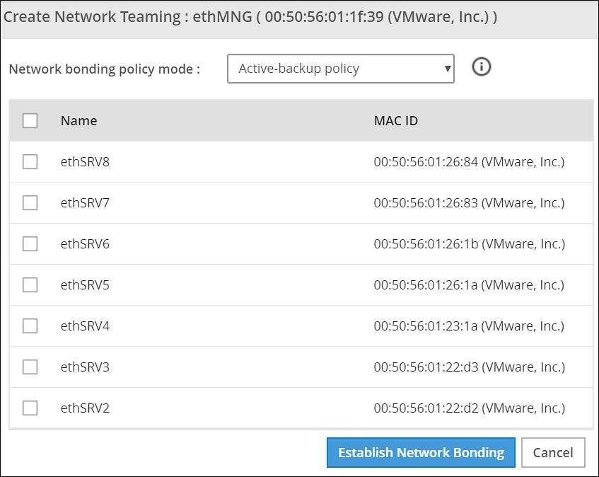
Ensure that the IP address is assigned to the interface on which you want to initiate the bond.
Select the following modes from the drop-down list:
- Active-backup policy
- Adaptive Load Balancing
Select the interfaces with which you want to create a bond.
Select Establish Network Bonding.A confirmation message appears.
Click OK.The bond is created, and the list appears on the Web UI.
Removing a Bond
Perform the following steps to remove a bond:
- On the Web UI, navigate to Settings > Network > Network Settings.The Network Settings screen appears with all the created bonds as shown in the following figure.
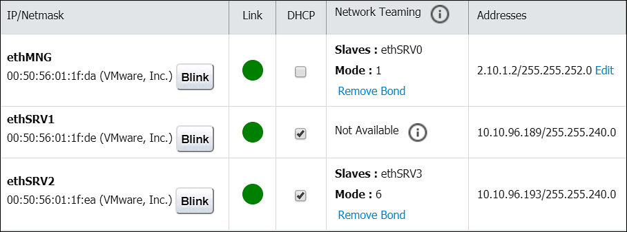
Under the Network Interfaces area, click Remove Bond corresponding to the interface on which the bonding is created.A confirmation screen appears.
Select OK.The bond is removed and the interfaces are visible on the IP/Network list.
Viewing a Bond
Using the DSG CLI Manager, you can view the bonds that are created between all the interfaces.
Perform the following steps to view a bond:
On the DSG CLI Manager, navigate to Networking > Network Settings.The Network Configuration Information Settings screen appears.
Navigate to Interface Bonding and select Edit.The Network Teaming screen displaying all the bonded interfaces appears as shown in the following figure.
Resetting the Bond
You can reset all the bonds that are created for an appliance. When you reset the bonds, all the bonds created are disabled. The slave NICs are reset to their initial state, where you can configure the network settings for them separately.
Perform the following steps to reset all the bonds:
On the DSG CLI Manager, navigate to Networking > Network Settings.The Network Configuration Information Settings screen appears.
Navigate to Interface Bonding and select Edit.The Network Teaming screen displaying all the bonded interfaces appears.
Select Reset.The following screen appears.
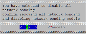
- Select OK.The bonding for all the interfaces is removed.
9 - Configuring Web Settings
Describes the procedure to configure the Web settings
Navigate to Settings > Network > Web settings, the Web Settings page contains the following sections:
- General Settings
- Session Management
- Shell In A Box Settings
- SSL Cipher Settings
9.1 - General Settings
Describes the General settings
The General Settings contains the following file upload configurations:
- Max File Upload Size
- File Upload Chunk Size
Increasing Maximum File Upload Size
By default, the maximum file upload size is set to 25 MB. You can increase the limit up to 4096 MB.
Perform the following steps to increase the maximum file upload size:
- From the ESA Web UI, proceed to Settings > Network > Web Settings.The Web Settings screen appears.

Move the Max File Upload Size slider to the right to increase the limit.
Click Update.
Increasing File Upload Chunk Size
By default, the file upload chunk size is set to 100 MB. You can increase the limit up to 512 MB.
Perform the following steps to increase the file upload chunk size:
- From the ESA Web UI, proceed to Settings > Network > Web Settings.The Web Settings screen appears.
Move the File Upload Chunk Size slider to the right to increase the limit.
Click Update.
9.2 - Session Management
Describes the procedure to manage the session
Only the admin user can extend the time using this option. The extended time becomes applicable to all users of the ESA.
Managing the session settings
Only the admin user can extend the time using this option. The extended time becomes applicable to all users of the ESA.
Perform the following steps to timeout using ESA Web UI option:
From the ESA Web UI, proceed to Settings > Network.
Click Web Settings.The following screen appears.

Move the Session Timeout slider to the right to increase the time, in minutes.
Click Update.
Fixing the Session Timeout
Perform the following steps to fix the session timeout.
There may be cases where the timeout session should be fixed, and the appliance logs out even if the session is an active session.
From the ESA Web UI, proceed to Settings > Network.
Click Web Settings.The following screen appears.
Move the Session Timeout slider to the right or left to increase or decrease the time, in minutes.
Select the Is hard timeout check box.
Click Update.
9.3 - Shell in a box settings
Describes the shell in a box settings
This setting allows a user with Appliance Web Manager permission to configure access to the Shell In A Box feature which is available through the Web UI. This setting applies to all the users that have access to the Web UI.
When enabled the users are able to view the CLI icon on the bottom right corner of the web page.
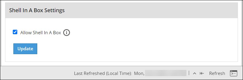
Perform the following steps to enable/disable Shell In A Box Settings.
From the ESA Web UI, proceed to Settings > Network.
Click Web Settings.The following screen appears.

To enable or disable the Shell In a Box Settings, select the Allow Shell In a Box check box.
Click Update.
9.4 - SSL cipher settings
Describes the SSL cipher settings
The ESA uses the OpenSSL library to encrypt and secure connections. You can configure an encrypted connection using the following two strings:
- SSL Protocols
- SSL Cipher Suites
The protocols and the list of ciphers supported by the ESA are included in the SSLProtocol and SSLCipherSuite strings respectively. The SSLProtocol supports SSL v2, SSL v3, TLS v1, TLS v1.1, TLS v1.2, and TLS v1.3 protocols.
To disable any protocol from the SSLProtocol string, prepend a hyphen (-) to the protocol. To disable any cipher suite from the SSLCipherSuite string, prepend an exclamation (!) to the cipher suite.
For more information about the OpenSSL library, refer to http://www.openssl.org/docs.
Using TLS v1.3
The TLS v1.3 protocol is introduced from v8.1.0.0. If you want to use this protocol, then ensure that you append the following cipher suite in the SSLCipherSuite text box.
TLS_AES_256_GCM_SHA384:TLS_CHACHA20_POLY1305_SHA256:TLS_AES_128_GCM_SHA256:ECDHE-RSA-AES128-GCM-SHA256:ECDHE-ECDSA-AES128-GCM-SHA256:ECDHE-RSA-AES256-GCM-SHA384:ECDHE-ECDSA-AES256-GCM-SHA384:DHE-RSA-AES128-GCM-SHA256:DHE-DSS-AES128-GCM-SHA256:kEDH+AESGCM:ECDHE-RSA-AES128-SHA256:ECDHE-ECDSA-AES128-SHA256:ECDHE-RSA-AES128-SHA:ECDHE-ECDSA-AES128-SHA:ECDHE-RSA-AES256-SHA384:ECDHE-ECDSA-AES256-SHA384:ECDHE-RSA-AES256-SHA:ECDHE-ECDSA-AES256-SHA:DHE-RSA-AES128-SHA256:DHE-RSA-AES128-SHA:DHE-DSS-AES128-SHA256:DHE-RSA-AES256-SHA256:DHE-DSS-AES256-SHA:DHE-RSA-AES256-SHA:AES128-GCM-SHA256:AES256-GCM-SHA384:AES128-SHA256:AES256-SHA256:AES128-SHA:AES256-SHA:AES:CAMELLIA:!aNULL:!eNULL:!EXPORT:!DES:!RC4:!MD5:!PSK:!aECDH:!EDH-DSS-DES-CBC3-SHA:!EDH-RSA-DES-CBC3-SHA:!KRB5-DES-CBC3-SHA
9.5 - Updating a protocol from the ESA Web UI
Describes the procedure to update a protocol using the ESA Web UI
Perform the following steps to update a protocol from the ESA Web UI:
In the ESA Web UI, navigate to Settings > Network > Web Settings.The Web Settings page appears.
Under SSL Cipher Settings tab, the SSLProtocol text box contains the value ALL-SSLv2-SSLv3.
Add
–to the required protocol.For example, to disable TLS1.1, type -TLSv1.1 in the SSLProtocol text box.

- Click Update to save the changes.
To re-enable TLSv1.1 using the Web UI, remove –TLSv1.1 from the SSLProtocol text box.
10 - Working with Secure Shell (SSH) Keys
Describes the procedure to configure the SSH Keys
The Secure Shell (SSH) is a network protocol that ensures an secure communication over unsecured network. A user connects to the SSH server using the SSH Client. The SSH protocol is comprised of a suite of utilities which provides high-level authentication encryption over unsecured communication channels.
A typical SSH setup consists of a host machine and a remote machine. A key pair is required to connect to the host machine through any remote machine. A key pair consists of a Public key and a Private key. The key pair allows the host machine to securely connect to the remote machine without entering a password for authentication.
For enhancing security, a Private key is secured using a passphrase. This ensures that only the rightful recipient can have access to the decrypted data. You can either generate key pairs or work with existing key pairs.
If you add a Private key without a passphrase, it is encrypted with a random passphrase. This passphrase is scrambled and stored.
If you choose a Private key with a passphrase, then the Private key is stored as it is. This passphrase is scrambled and stored.
For more information about generating the SSH key pairs, refer Adding a New Key.
The SSH protocol allows an authorized user to connect to the host machines from the remote machines. Both inbound communication and outbound communication are supported using the SSH protocol. An authorized user is a combination of an appliance user associated with a valid key pair. An authorized user must be listed as a valid recipient to connect using the SSH protocol.
The SSH protocol allows the authorized users to run tasks securely on the remote machine. When the users connect to the appliance using the SSH protocol, then the communication is known as inbound communication.
For more information about inbound SSH configuration, refer here.
When the users connect to a known host using their private keys, then the communication is known as outbound communication. The authorized users are allowed to initiate the SSH communication from the host.
For more information about outbound SSH configuration, refer here.
On the ESA Web UI, you can configure all the following standard aspects of SSH:
- Authorized Keys
- Identities Keys
- Known Hosts
SSH pane:With the SSH configuration Manager you can examine and manage the SSH configuration. The SSH keys can be configured in the Authentication Configuration pane on the ESA Web UI.
The following figure shows the SSH Configuration Manager pane.

Authentication Type:The SSH Server is configured in the following three ways:
- Password
- Public Key
- Password + publickey
| Authentication Type | Description |
|---|---|
| Password | In this authentication type, only the password is required for authentication to the SSH server. The public key is not required on the server for authentication. |
| Public Key | In this authentication type, the server requires only the public key for authentication. The password is not required for authentication. |
| Password + Public key | In this authentication type, the server can accept both, the keys and the password, for authentication. |
SSH Mode:
From the Web UI, navigate to Settings > Network > SSH. Using the SSH mode, restrictions for SSH connections can be set. The restrictions can be hardened or loosened based on the needs. There are four modes SSH mode types are shown below.
| Mode | SSH Server | SSH Client |
|---|---|---|
| Paranoid | Disable root access | Disable password authentication, that is, allow to connect only using public keys. Block connections to unknown hosts. |
| Standard | Disable root access | Allow password authentication. Allow connections to new (unknown) hosts, enforce SSH fingerprint of known hosts. |
| Open | Allow root access Accept connections using passwords and public keys. | Allow password authentication. Allow connection to all hosts – do not check hosts fingerprints. |
10.1 - Configuring the authentication type for SSH keys
Describes the procedure to configure the authentication type for SSH Keys
Perform the following steps to configure the SSH Key Authentication Type.
From the ESA Web UI, navigate to Settings > Network.The Network Settings pane appears.
Select the SSH tab.The SSH Configuration Manager pane appears.
Select the authentication type from the Authentication Type drop down menu.

Select the SSH mode from the SSH Mode drop down menu.
Click Apply.A message Configuration saved successfully appears.
10.2 - Configuring inbound communications
Describes the procedure to configure the inbound communication for SSH Keys
The users who are allowed to connect to the ESA using SSH are listed in the Authorized Keys (Inbound) tab.
The following screen shows the Authorized Keys.
")
Adding a New Key
An authorized key has to be created for a user or a machine to connect to an ESA on the host machine.
Perform the following steps to add a new key.
From the ESA Web UI, navigate to Settings > Network.The Network Settings pane appears
Select the SSH tab.The SSH Configuration Manager pane appears.
Select the Authorized Keys (Inbound) tab.
Click Add New Key.The Add New Authorized Key dialog box appears.
Select a user.
Select Generate new public key.
The Root password is required to create Authorized Key prompt appears. Enter the root password and click Ok.
If the private key is to be saved, then select Click To Download Private Key.The private key is saved to the local machine.
If the public key is to be saved, then select Click To Download Public Key.The public key is saved to the local machine.
Click Finish.The new authorized key is added.
Uploading a Key
You can assign a public key to a user by uploading the key from the Web UI.
Perform the following steps to upload a key.
From the ESA Web UI, navigate to Settings > Network.The Network Settings pane appears.
Select the SSH tab.The SSH Configuration Manager pane appears.
Select the Authorized Keys (Inbound) tab.
Click Add New Key.The Add New Authorized Key dialog box appears.
Select a user.
Select Upload public key.The file browser dialog box appears.
Select a public key file.
Click Open.
The Root password is required to create Authorized Key prompt appears. Enter the root password and click Ok.The key is assigned to the user.
Reusing public keys between users
The public key of one user can be assigned as a public key of another user.
Perform the following steps to upload an existing key.
From the ESA Web UI, navigate to Settings > Network.The Network Settings pane appears.
Select the SSH tab.The SSH Configuration Manager pane appears.
Select the Authorized Keys (Inbound) tab.
Click Add New Key.The Add New Authorized Key dialog box appears.
Select a user.
Select Choose from existing keys.
Select the public key.
The Root password is required to create Authorized Key prompt appears. Enter the root password and click Ok.The public key is assigned to the user.
Downloading a Public Key
From the Web UI, you can download the public of a user to the local machine.
Perform the following steps to download a key.
From the ESA Web UI, navigate to Settings > Network.The Network Settings pane appears.
Select the SSH tab.The SSH Configuration Manager pane appears.
Select the Authorized Keys (Inbound) tab.
Select a user.
Select Download Public Key.The public key is saved to the local directory.
Deleting an Authorized Key
You can remove a key from the authorized users list. Once the key is removed from the list, the remote machine will no longer be able to connect to the host machine.
Perform the following steps to delete an authorized key:
From the ESA Web UI, navigate to Settings > Network.The Network Settings pane appears
Select the SSH tab.The SSH Configuration Manager pane appears.
Select the Authorized Keys (Inbound) tab.
Select a user.
Select Delete Authorized Key.A message confirming the deletion appears.
Click Yes.
The Root password is required to delete Authorized Key prompt appears. Enter the root password and click Ok.The key is deleted from the authorized keys list.
Clearing all Authorized Keys
You can remove all the public keys from the authorized keys list.
Perform the following steps to clear all keys:
From the ESA Web UI, navigate to Settings > Network.The Network Settings pane appears.
Select the SSH tab.The SSH Configuration Manager pane appears.
Select the Authorized Keys (Inbound) tab.
Click Reset List.A message confirming the deletion of all authorized keys appears.
Click Yes.
The Root password is required to delete all Authorized Keys prompt appears. Enter the root password and click Ok.All the keys are deleted.
10.3 - Configuring outbound communications
Describes the procedure to configure the outbound communication for SSH Keys
The users who can connect to the known hosts with their private keys are listed in the Identities Keys (Outbound) tab.
The following screen shows the Identities.
")
Adding a New Key
A new public key can be generated for the host machine to connect with another machine.
Perform the following steps to add a new key.
From the ESA Web UI, navigate to Settings > Network.The Network Settings pane appears.
Select the SSH tab.The SSH Configuration Manager pane appears.
Select the Identities Keys (Outbound) tab.
Click Add New Key.The Add New Identity Key dialog box appears.
Select a user.
Select Generate new keys.
The Root password is required to create Identity Key prompt appears. Enter the root password and click Ok.
If the public key is to be saved, then select Click to Download Public Key .The public key is saved to the local machine.
Click Finish.The new authorized key is added.
Downloading a Public Key
You can download the host’s public key from the Web UI.
Perform the following steps to download a key.
From the ESA Web UI, navigate to Settings > Network.The Network Settings pane appears.
Select the SSH tab.The SSH Configuration Manager pane appears.
Select the Identities Keys (Outbound) tab.
Select a user.
Select Download Public Key.The public key is saved to the local machine.
Uploading Keys
Perform the following steps to upload an existing key.
From the ESA Web UI, navigate to Settings > Network.The Network Settings pane appears.
Select the SSH tab.The SSH Configuration Manager pane appears.
Select the Identities Keys (Outbound) tab.
Click Add New Key.The Add New Identity Key dialog box appears.
Select a user.
Select Upload Keys.The list of public keys with the users that they are assigned to appears.
Select Upload Public Key.The file browser dialog box appears.
Select a public key file from your local machine.
Click Open.The public key is assigned to the user.
Select Upload Private Key.The file browser dialog box appears.
Select a private key file from your local machine.
Click Open.
If the private key is protected by a passphrase, then the text field Private Key Passphrase appears.Enter the private key passphrase.

- Click Finish.The new identity key is added.
Reusing public keys between users
The public and private key pair of one user can assigned as a public and private key pair of another user.
Perform the following steps to choose from an existing key.
From the ESA Web UI, navigate to Settings > Network.The Network Settings pane appears.
Select the SSH tab.The SSH Configuration Manager pane appears.
Select the Identities Keys (Outbound) tab.
Click Add New Key.The Add New Identity Key dialog box appears.
Select a user.
Select Choose from existing keys.
Select the public key.
The Root password is required to create Identity Key prompt appears. Enter the root password and click Ok.The public key is assigned to the user.
Deleting an Identity
You can delete an identity for a user. Once the identity is removed, the user will no longer be able to connect to another machine.
Perform the following steps to delete an identity:
From the ESA Web UI, navigate to Settings > Network.The Network Settings pane appears.
Select the SSH tab.The SSH Configuration Manager pane appears.
Select the Identities Keys (Outbound) tab.
Select a user.
Click Delete Identity.A message confirming the deletion appears.
Click Yes.
The Root password is required to delete the Identity Key prompt appears. Enter the root password and click Ok.The identity is deleted.
Clearing all Identities
You can remove all the public keys from the authorized keys list.
Perform the following steps to clear all identities.
From the ESA Web UI, navigate to Settings > Network.The Network Settings pane appears.
Select the SSH tab.The SSH Configuration Manager pane appears.
Select the Identities Keys (Outbound) tab.
Click Reset Identity List.A message confirming the deletion of all identities appears.
Click Yes.
The Root password is required to delete all Identity Keys prompt appears. Enter the root password and click Ok.All the identities are deleted.
10.4 - Configuring known hosts
Describes the procedure to configure the known hosts for SSH Keys
By default, the SSH is configured to deny all the communications to unknown remote servers. Known hosts list the machines or nodes to which the host machine can connect to. The SSH servers to which the host can communicate with are added under Known Hosts.
Adding a New Host
You can add a host to the list of known hosts that can have a connection established.
Perform the following steps to add a host.
From the ESA Web UI, navigate to Settings > Network.The Network Settings pane appears.
Select the SSH tab.The SSH Configuration Manager pane appears.
Select the Known Hosts tab.
Click Add Host.The Enter the ip/hostname dialog box appears.
Enter the IP address or hostname in the Enter the ip/hostname text box.
Click Ok.All host is added to the known hosts list.
Updating the Host Keys
You can refresh the hostnames to check for updates to host’s public keys.
Perform the following steps to updated a host key.
From the ESA Web UI, navigate to Settings > Network.The Network Settings pane appears.
Select the SSH tab.The SSH Configuration Manager pane appears.
Select the Known Hosts tab.
Select a host name.
Click Refresh Host Key.The key for the host name is updated.
Deleting a Host
If a connection to a host is no longer required, then you can delete the host from the known host list.
Perform the following steps to delete a known host.
From the ESA Web UI, navigate to Settings > Network.The Network Settings pane appears.
Select the SSH tab.The SSH Configuration Manager pane appears.
Select the Known Hosts tab.
Select a host name.
Click Delete Host.A message confirming the deletion appears.
Click Yes.The host is deleted.
Resetting the Host Keys
You can set the keys of all the hosts to a default value.
Perform the following steps to reset all the host keys:
From the ESA Web UI, navigate to Settings > Network.The Network Settings pane appears.
Select the SSH tab.The SSH Configuration Manager pane appears.
Select the Known Hosts tab.
Select Reset Host Keys.A message confirming the reset appears.
Click Yes.The host keys for all the hostnames is set to a default value.