Command-Line Interface (CLI) Manager is a Protegrity Platform tool for managing the Protegrity appliances, such as, the ESA and DSG. CLI Manager is a text-based environment for managing status, administration, configuration, preferences, and networking of your appliance. This section describes how to login to the ESA CLI Manager, and its many features.
This is the multi-page printable view of this section. Click here to print.
Command-Line Interface (CLI) Manager
- 1: Accessing the CLI Manager
- 2: CLI Manager Structure Overview
- 3: Working with Status and Logs
- 3.1: Monitoring System Statistics
- 3.2: Viewing the Top Processes
- 3.3: Working with System Statistics (SYSSTAT)
- 3.4: Auditing Service
- 3.5: Viewing Appliance Logs
- 3.6: Viewing User Notifications
- 4: Working with Administration
- 4.1: Working with Services
- 4.2: Setting Date and Time
- 4.3: Managing Accounts and Passwords
- 4.4: Working with Backup and Restore
- 4.5: Setting Up the Email Server
- 4.6: Working with Azure AD
- 4.6.1: Configuring Azure AD Settings
- 4.6.2: Enabling/Disabling Azure AD
- 4.7: Accessing REST API Resources
- 4.7.1: Using Basic Authentication
- 4.7.2: Using Client Certificates
- 4.7.3: Using JSON Web Token (JWT)
- 4.8: Securing the GRand Unified Bootloader
- 4.9: Working with Installations and Patches
- 4.9.1: Add/Remove Services
- 4.9.2: Uninstalling Products
- 4.9.3: Managing Patches
- 4.10: Managing LDAP
- 4.10.1: Working with the Protegrity LDAP Server
- 4.10.2: Changing the Bind User Password
- 4.10.3: Working with Proxy Authentication
- 4.10.4: Configuring Local LDAP Settings
- 4.10.5: Monitoring Local LDAP
- 4.10.6: Optimizing Local LDAP Settings
- 4.11: Rebooting and Shutting down
- 4.12: Accessing the OS Console
- 5: Working with Networking
- 5.1: Configuring Network Settings
- 5.2: Configuring SNMP
- 5.3: Working with Bind Services and Addresses
- 5.4: Using Network Troubleshooting Tools
- 5.5: Managing Firewall Settings
- 5.6: Using the Management Interface Settings
- 5.7: Ports Allowlist
- 6: Working with Tools
- 6.1: Configuring the SSH
- 6.1.1: Specifying SSH Mode
- 6.1.2: Setting Up Advanced SSH Configuration
- 6.1.3: Managing SSH Known Hosts
- 6.1.4: Managing Authorized Keys
- 6.1.5: Managing Identities
- 6.1.6: Generating SSH Keys
- 6.1.7: Configuring the SSH
- 6.1.8: Customizing the SSH Configurations
- 6.1.9: Exporting/Importing the SSH Settings
- 6.1.10: Securing SSH Communication
- 6.2: Clustering Tool
- 6.2.1: Creating a TAC using the CLI Manager
- 6.2.2: Joining an Existing Cluster using the CLI Manager
- 6.2.3: Cluster Operations
- 6.2.4: Managing a site
- 6.2.5: Node Management
- 6.2.5.1: Show Cluster Nodes and Status
- 6.2.5.2: Viewing the Cluster Status using the CLI Manager
- 6.2.5.3: Adding a Remote Node to a Cluster
- 6.2.5.4: Updating Cluster Information using the CLI Manager
- 6.2.5.5: Managing Communication Methods for Local Node
- 6.2.5.6: Managing Local to Remote Node Communication
- 6.2.5.7: Removing a Node from a Cluster using CLI Manager
- 6.2.5.8: Uninstalling Cluster Services
- 6.2.6: Trusted Appliances Cluster
- 6.2.6.1: Updating Cluster Key
- 6.2.6.2: Redeploy Local Cluster Configuration to All Nodes
- 6.2.6.3: Cluster Service Interval
- 6.2.6.4: Execute Commands as OS Root User
- 6.3: Working with Xen Paravirtualization Tool
- 6.4: Working with the File Integrity Monitor Tool
- 6.5: Rotating Appliance OS Keys
- 6.6: Managing Removable Drives
- 6.7: Tuning the Web Services
- 6.8: Tuning the Service Dispatcher
- 6.9: Working with Antivirus
- 7: Working with Preferences
- 7.1: Viewing System Monitor on OS Console
- 7.2: Setting Password Requirements for CLI System Tools
- 7.3: Viewing user notifications on CLI load
- 7.4: Minimizing the Timing Differences
- 7.5: Setting a Uniform Response Time
- 7.6: Limiting Incorrect root Login
- 7.7: Enabling Mandatory Access Control
- 7.8: FIPS Mode
- 7.9: Basic Authentication for REST APIs
- 8: Command Line Options
1 - Accessing the CLI Manager
You log on to the CLI Manager to manage the settings and monitor the ESA. The CLI Manager is available using any of the following text consoles:
- Direct connection using local keyboard and monitor.
- Serial connection using an RS232 console cable.
- Network connection using a Secure Shell (SSH port 22) connection to the appliance management IP address.For more information about listening ports, refer Open listening ports.
To log on to the CLI Manager:
From the ESA Web UI pane, click the window that appears at the bottom right.
A new CLI Manager window opens.
At the prompt, type the admin login credentials set during the appliance installation.
Press ENTER.
The CLI Manager screen appears.
First time login
When you login through the CLI Manager or the Web UI for the first time, with the password policy enabled, the Update Password screen appears. It is recommended that you change the password since the administrator sets the initial password.
Shell Accounts role with Shell Access
If you are a user associated to Shell Accounts role with Shell (non-CLI) Access permissions, you cannot access the CLI or Web UI. This is an exception when the user has the password policy enabled and is required to change the password through the Web UI.
For more information about configuring the password policy, refer to section Password Policy Configuration.
CLI Manager Main Screen
The CLI Manager screen appears when you successfully login to the CLI Manager. This screen appears with the messages that relate to the user who has logged in and also mentions the priority of each message. Note here that % to the bottom-right of the screen indicates the information available for viewing on the screen.

If you click Continue, then the CLI Manager main screen appears.
The following figure illustrates the CLI Manager main screen.
")
CLI Manager Navigation
There are many common keystrokes that help you to navigate the CLI Manager. The following table describes the navigation keys.
| Key | Description |
|---|---|
| UP ARROW DOWN ARROW | Navigates up and down menu options |
| ENTER | Selects an option or continues process |
| Q | Quits the CLI Manager |
| T | Goes to the top of the current menu |
| U | Moves up one level |
| H | Displays key settings and instructions |
| TAB | Moves between multiple fields |
| Page Up | Scroll Up |
| Page Down | Scroll Down |
In the following sections, the main system menus in the CLI manager are explained in detail.
2 - CLI Manager Structure Overview
There are five main system menus in the CLI Manager:
- Status and Logs
- Administration
- Networking
- Tools
- Preferences
Status and Logs
Status and Logs menu includes four options that make the analysis of logs easier.
- System Monitor tool with real-life information on the CPU, network, and disk usage.
- Top Processes view having a list of 10 top memory and CPU users. The information is updated periodically.
- Appliance Logs tool, divided into subcategories. These can be appliance common logs and appliance specific logs. Thus, you can view system event logs that relate to, for example, syslog, installation, kernel, and web services engine logs which are common for all Protegrity appliances.
- User Notifications tool include all the messages for a user. The latest notifications are also displayed on the screen after login.
For more information about status and logs, refer to section Working with Status and Logs.
Administration
Using Administration menu, perform most of the standard server administration tasks.
- Start/stop/restart services
- Change time/time zone/date/NTP server
- Change passwords for admin/viewer/root user/LDAP users and unlock locked users
- Backup/restore OS, appliance configuration
- Set up email (SMTP)
- JWT Configuration
- Azure AD Configuration
- Install/uninstall services and patches
- Set up communication with a directory server (Local/external LDAP, Active Directory) and monitor the LDAP
- Reboot and shut down
- Access appliance OS console
For more information about ESA administration, refer to section Working with Administration.
Networking
Using the Networking menu, configure the network settings as per your requirements.
- Change host name, appliance address, gateway, domain information
- Configure SNMP – refresh/start/set service or show/set string
- Specify management interface for Web UI and Web Services
- Configure network interface settings and assign services to multiple IP addresses
- Troubleshoot the network
- Manage Firewall settings
- Ports Allowlist
For more information about ESA networking, refer to section Working with Networking.
Tools
Using the Tools menu, perform the following tasks in ESA.
- Configure SSH mode to include known hosts/authorized keys/identities, and generate new server key
- Set up trusted appliances cluster
- Set up XEN paravirtualization
- View status of external hard drives
- Run antivirus and update signature file
- Configure Web services settings
For more information about tools, refer to section Working with Tools.
If you are using DSG, then you have additional tools for configuring ESA communication. Refer to the appropriate Appliance guide for details.
The additional tools for logging and reporting and policy management mentioned in the list are specifically for configuring ESA appliance.
Preferences
Using the Preferences menu, perform the following tasks.
- Set up local console settings
- Specify if root password is required for the CLI system tools
- Display the system monitor in OS console
- Minimize timing differences
- Set uniform response time for failed login
- Enable root credentials check limit
- Enable AppArmor
- Enable FIPS Mode
- Basic Authentication for REST APIs
For more information about preferences, refer to section Working with Preferences.
3 - Working with Status and Logs
The Status and Logs screen allows you to access system monitor information, examine top memory and CPU usage, and view appliance logs. You can access it from the CLI Manager main screen. This screen shows the hostname to which you are connected, and it allows you to view and manage your audit logs.
The following figure shows the Status and Logs screen.

In addition to the existing logs, the following additional security logs are generated:
- Appliance’s own LDAP when users are added and removed.
- SUDO commands are issued from the shell.
- There are failed attempts to log in from SSH or Web UI.
- All shell commands: This is a PCI-DSS requirement.
3.1 - Monitoring System Statistics
Using System Monitor, you can view the following system statistics.
- CPU usage
- RAM
- Disk space free or in use.
- If more hard disks are required, and so on.
To view the system information, login to the CLI Manager, navigate to Status and Logs > System Monitor.

3.2 - Viewing the Top Processes
Using Top Processes, you can examine in real-time, the processes using up memory or CPU.
To view the top processes, login to the CLI Manager, navigate to Status and Logs > Top Processes.

3.3 - Working with System Statistics (SYSSTAT)
The System Statistics (SYSSTAT) is a tool to monitor system resources and their performance on LINUX/UNIX systems. It contains utilities that collect system information, report CPU statistics, report input-output statistics, and so on. The SYSSTAT tool provides an extensive and detailed data for all the activities in your system.
The SYSSTAT contains the following utilities for analyzing your system:
- sar
- iostat
- mpstat
- pidstat
- nfsiostat
- cisfsiostat
These utilities collect, report, and save system activity information. Using the reports generated, you can check the performance of your system.
The SYSSTAT tool is available when you install the appliance.
On the Web UI, navigate to System > Task Scheduler to view the SYSSTAT tasks. You must run the following tasks to collect the system information:
- Sysstat Activity Report to collect information at short intervals
- Sysstat Activity Summary to collect information at a specific time daily
The following figure displays the SYSSTAT tasks on the Web UI.

The logs are stored in the /var/logs/sysstat directory.
The tasks are disabled by default. You must enable the tasks from the Task Scheduler for collecting the system information.
3.4 - Auditing Service
The Linux Auditing System is a tool or utility that allows to monitor events occurring in a system. It is integrated with the kernel to watch the system operations. The events that must be monitored are added as rules and defined to which extent that the event must be tracked. If the event is triggered, then a detailed audit log is generated. Based on this log, you can track any violations to the system and improve security measures to prevent them.
In Protegrity appliances, the auditing tool is implemented to track certain events that can pose as a security threat. The Audit Service is installed and running in the appliance for this purpose. On the Web UI, navigate to System > Services to view the status of the service. The Audit Service runs to check the following events:
- Update timezone
- Update AppArmor profiles
- Manage OS users and their passwords
If any of these events occur, then a low severity log is generated and stored in the logs. The logs are available in the /var/log/audit/audit.log directory. The logs that are generated by the auditing tool, contain detailed information about modifications triggered by the events that are listed in the audit rules. This helps to differentiate between a simple log and an audit log generated by the auditing tool for monitoring potential risks to the appliance.
For example, consider a scenario where an OS user is added to the appliance. If the Audit Service is stopped, then details of the user addition are not displayed and logs contain entries as illustrated in the following figure.

If the Audit Service is running, then the same event triggers a detailed audit log describing the user addition. The logs are illustrated in the following figure.

As illustrated in the figure, the following are some audits that are triggered for the event:
- USER_CHAUTHOK: User attribute is modified.
- EOE: Multiple record event ended.
- PATH: Recorded a path file name.
Thus, based on the details provided in the type attribute, a potential threat to the system can be monitored.
For more information about the audit types, refer to the following link:
On the Web UI, an Audit Service Watchdog scheduled task is added to ensure that the Audit Service is running. This task is executed once every hour.
Caution: It is recommended to keep the Audit Service running for security purposes.
3.5 - Viewing Appliance Logs
Using Appliance Logs, you can view all logs that are gathered by the appliance.
To view the appliance logs, login to the CLI Manager, navigate to Status and Logs > Appliance Logs.
These logs are listed in the following table:
Table: Appliance Logs
Logs | Logs Types | Description | Appliances
Specific | |
ESA | DSG | |||
System Event Logs | Syslog | All appliance logs. | ✓ | ✓ |
Installation | Installation logs contain all of the information
gathered during the installation procedure. These logs include all
errors during installation and information on all the processes,
resources, and settings used for installation. | ✓ | ✓ | |
Patches | Patches installed on appliance | ✓ | ✓ | |
Patch_SASL | Proxy Authentication (SASL) related logs | |||
Authentication | Authentication logs, such as user logins. | ✓ | ✓ | |
Web Services | Logs generated by the Web Services modules. | ✓ | ✓ | |
Web Management | Logs generated by the Appliance Web UI engine | ✓ | ✓ | |
Current Event | Current event logs contain all the operations performed
on the appliance. It gathers all information from different
services and appliance components. | ✓ | ✓ | |
Kernel | System kernel logs. | ✓ | ✓ | |
Web Services Server | Web Services Apache logs | ✓ | ✓ | |
Patch_Logging | Logging server related logs such as
installation log: logging server and so on. | ✓ | ✓ | |
Web Services Engine | Web Services HTTP-Server logs | Appliance Web UI related logs. | ✓ | ✓ |
Service Dispatcher | Access Logs | Service Dispatcher Access Logs | ✓ | ✓ |
Server Logs | Service Dispatcher Server Logs | ✓ | ✓ | |
PEP Server | Logs received from PEP Server that is located on the FPV
and DSG. | ✓ | ||
Cluster Logs | Export Import Cluster | ✓ | ||
DSG Patch Installation | Cluster | Log all operations performed during installation of the
DSG patch | ✓ | |
You can delete the desired logs using the Purge button and view them in real-time using the Real-Time View button. When you finish viewing the logs, press Done to exit.
3.6 - Viewing User Notifications
All the messages that display when you log in to either to the Web UI or CLI Manager can be viewed here as well.
To view the user notifications, login to the CLI Manager, navigate to Status and Logs > User Notifications.

4 - Working with Administration
Appliance administration is the most important part of the appliance framework. Most of the administrative tools and tasks can be performed using the Administration menu of the CLI Manager.
The following screen illustrates the Administration screen on the CLI Manager.

Some of the administration tasks, such as creating clustered environment or setting up the virtualization can be done only in the CLI Manager by selecting the Administration menu. Most of the administration tasks can be performed using the Web UI.
4.1 - Working with Services
You can manually start and stop appliance services.
To view all appliance services and their statuses, login to the CLI Manager, navigate to Administration > Services.
Use caution before stopping or restarting a particular service. Make sure that no important actions are being performed by other users using the service that must be stopped or restarted.
Some services, such as, LDAP Proxy auth, member source services, and so on, are available after they have been successfully configured on ESA.
In the Services dialog box, you can start, stop, or restart the following services:
Table 1. Appliance Services
| Services | ESA | DSG |
| OS | ✓ | ✓ |
| Web UI, Secure Shell (SSH), Firewall, Real-time Graphs, SNMP Service, NTP Service, Cluster Status, Appliance Heartbeat Server, Appliance Heartbeat Client, Log Filter Server, Messaging System, Appliance Queues Backend, Docker, Rsyslog Service | ||
| LDAP | ✓ | ✓ |
| LDAP Server, Name Service Cache Daemon | ||
| Web Services Engine | ✓ | ✓ |
| Web Services Engine | ||
| Service Dispatcher | ✓ | ✓ |
| Service Dispatcher | ||
| Logging | ✓ | |
| Management Server, Management Server Database, Reports Repository, Reporting Engine | ||
| Policy Management | ✓ | |
Policy Repository, HubController, PIM Cluster, Soft HSM
Gateway, Key Management Gateway, Member Source Service,
Meteringfacade, DevOps, Logfacade For more information about
the Meteringfacade and Logfacade services, refer to the section
Services. | ||
| Reporting Server | ✓ | |
| Reports repository and reporting engine | ||
| Distributed Filesystem File Protector | ✓ | |
DFS Cache Refresh | ||
| ETL Toolkit | ||
| ETL Server | ||
| Cloud Gateway | ✓ | |
| Cloud Gateway Cluster | ||
| td-agent | ✓ | ✓ |
| td-agent | ||
| Audit Store | ✓ | |
| Audit Store Repository | ||
| Audit Store Management | ||
| Analytics | ✓ | |
| Analytics, Audit Store Dashboards | ||
| RPS | ✓ |
You can change the status of any service when you select it from the list and choose Select. In the screen that follows the Service Management screen, select stop, start, or restart a service, as required.
When you apply any action on a particular service, the status message appears with the action applied. Press ENTER again to continue.
You can also use the Web UI to start or stop services. In the Web UI Services, you have additional options for stopping/starting services, such as Enable/Disable Auto-start for most of the services.
Important: Although the services can be started or stopped from the Web UI, the start/stop/restart action is restricted for some services, such as, networking, td-agent, docker, exim4, and so on. These services can be operated from the OS Console. Run the following command to start/stop/restart a service.
/etc/init.d/<service_name> stop/start/restart
For example, to start the docker service, run the following command.
/etc/init.d/docker start
4.2 - Setting Date and Time
You can adjust the date and time settings of ESA by navigating to Administration > Date and Time. You may need to do so if this information was entered incorrectly during initialization.
You can synchronize time with NTP Server using the Time Server (NTP) option (explained in the following paragraph), change time zone using the Set Time Zone option, change date using the Set Date option, or change time using the Set Time option. The information selected during installation is available beside each option.
Use an Up Arrow or Down Arrow key to change the values in the editable fields, such as Month/Year. Use any arrow key to navigate the calendar. Use the Tab key to navigate between the editable fields.

The first column in the calendar shows the corresponding week number
You can set the time and date using the Web UI as well.
For more information about setting the ESA time and date, refer to section Configuring Date and Time.
License, certificates, and date and time modifications
Date and time modifications may affect licenses and certificates. It is recommended to have time synchronized between Appliances and Protectors.
Configure NTP Time Server
You must enable or disable the NTP settings only from the CLI Manager or Web UI.
You can access the Configure Server NTP Time Server screen by navigating to Administration > Date and Time > Time Server option.

To enable NTP synchronization, you need to specify the NTP Server first and then enable NTP. Once the NTP Server is specified, the new time will be applied immediately.
The NTP synchronization may take some time and while it is in progress, the Synchronization Status displays In Progress. When it is over, the Synchronization Status displays Time Synchronized.
4.3 - Managing Accounts and Passwords
The ESA CLI Manager includes options to change password and permissions for multiple users through the CLI interface. The options available are listed as follows:
- Change My Password
- Manage Password and Local-Accounts
- Reset directory user-password
- Change OS root account password
- Change OS local_admin account password
- Change OS local_admin account permissions
- Manage internal Service-Accounts
- Manage local OS users
OS Users in Appliances
When you install an appliance, some users are installed to run specific services for the products.
When adding users, ensure that you do not add the OS users as policy users.
The following table describes the OS users that are available in your appliance.
| OS Users | Description |
|---|---|
| alliance | Handles DSG processes |
| root | Super user with access to all commands and files |
| local_admin | Local administrator that can be used when an LDAP user is not accessible |
| www-data | Daemon that runs the Apache, Service dispatcher, and Web services as a user |
| ptycluster | Handles TAC related services and communication between TAC through SSH. |
| service_admin and service_viewer | Internal service accounts used for components that do not support LDAP |
| clamav | Handles ClamAV antivirus |
| rabbitmq | Handles the RabbitMQ messaging queues |
| epmd | Daemon that tracks the listening address of a node |
| openldap | Handles the openLDAP utility |
| dpsdbuser | Internal repository user for managing policies |
Strengthening Password Policy
Passwords are a common way of maintaining a security of a user account. The strength and complexity of a password are some of the primary requirements of an enterprise to prevent security vulnerability. A weak password increases chances of a security breach. Thus, to ensure a strong password, different password policies are set to enhance the security of an account.
Password policies are rules that enforce validation checks to provide a strong password. You can set your password policy based on the enterprise ordinance. Some requirements of a strong password policy might include use of numerals, characters, special characters, password length, and so on.
The default requirements of a strong password policy for an appliance OS user are as follows.
- The password must have at least 8 characters.
- All the printable ASCII characters are allowed.
- The password must contain at least one character each from any of the following two groups:
- Numeric: Includes numbers from 0-9.
- Alphabets: Includes capitals [A-Z] and small [a-z] alphabets.
- Special characters: Includes ! " # $ % & ( ) * + , - . / : ; < > = ? @ [ \ ] ^ _ ` { | } ~
You can enforce password policy rules for the LDAP and OS users by editing the check_password.py file. This file contains a Python function that validates a user password. The check_password.py file is run before you set a password for a user. The password for the user is applied only after it is validated using this Python function.
For more information about password policy for LDAP users, refer here.
Enforcing Password Policy
The following section describes how to enforce your policy restrictions for the OS and LDAP user accounts.
To enforce password policy:
Login to the CLI Manager.
Navigate to Administration > OS Console.
Enter the root password and select OK.
Edit the check_password.py file using a text editor.
/etc/ksa/check_password.pyDefine the password rules as per your organizational requirements.
For more information about the password policy examples, refer here.
Save the file.
The password rules for the users in ESA are updated.
Examples
The following section describes a few scenarios about enforcing validation checks for the LDAP and OS users.
The check_password.py file contains the def check_password (password) Python function. In this function you can define your validations for the user password. This function returns a status code and a status message. In case of successful validation, the status code is zero and the status message is empty. In case of validation failure, the status code is non-zero and the status message contains the appropriate error message.
Scenario 1:
An enterprise wants to implement the following password rules:
- Length of the password should contain atleast 15 characters
- Password should contain digits
You must add the following snippet in the def check_password (password) function:
# Password length check
if len(password)<15: return (1,"Password should contain at least 15 characters")
# Password digits check
password_set=set(password)
digits=set(string.digits)
if ( password_set.intersection(digits) == set([]) ): return (2,"Password must contain digit)
Scenario 2:
An enterprise wants to implement the following password rule:
- Password should not contain 1234.
You must add the following snippet in the def check_password (password) function:
if password==1234:
return (1,"Password must not contain 1234")
return (0,None)
Scenario 3:
An enterprise wants to implement the following password rules:
- Password should contain a combination of uppercase, lowercase, and numbers.
You must add the following snippet in the def check_password (password) function:
digits=set(string.digits)
if ( password_set.intersection(digits) == set([]) ): return (2,"Password must contain numbers, upper, and lower case characters.")
# Force lowercase
lower_letters=set(string.ascii_lowercase)
if ( password_set.intersection(lower_letters) == set([]) ): return (2,"Password must contain numbers, upper, and lower case characters")
# Force uppercase
upper_letters=set(string.ascii_uppercase)
if ( password_set.intersection(upper_letters) == set([]) ): return (2,"Password must contain numbers, upper ,and lower case characters")
Changing Current Password
In situations where you need to change your current password due to suspicious activity or reasons other than password expiration, you can use the following steps.
For more information about appliance users, refer here.
To change the current password:
Login to the CLI Manager.
Navigate to Administration > Accounts and Passwords > Change My Password.
In the Current password field, type the current password.
In the New Password field, type the new password.
In the Retype Password field, retype the new password.
Select OK and press ENTER to save the changes.
Resetting Directory Account Passwords
You can change the password for any user existing in the internal LDAP directory. The user accounts and their security privileges as well as passwords are defined in the LDAP directory.
To be able to change the password for any LDAP user, you need to provide Administrative LDAP user credentials. You can also provide the old credentials of the LDAP user.
The LDAP Administrator is an admin user or the Directory Administrator assigned by admin. Admin can define Directory Administrators in the LDAP directory.
For more information about the internal LDAP directory, refer here.
To change a directory account password:
Login to the CLI Manager.
Navigate to Administration > Accounts and Passwords > Manage Passwords and Local-Accounts > Reset directory user-password.
In the displayed dialog box, in the Administrative LDAP user name or local_admin and Administrative user password fields, enter the Administrative LDAP user name and password. You can also use the local_admin credentials.
In the Target LDAP user field, enter the LDAP user name you wish to change the password for.
In the Old password field, enter the old password for the selected LDAP user. This step is optional.
In the New password field, enter a new password for the selected LDAP user.
In the Confirm new password field, re-enter a new password for the selected LDAP user.
Select OK and press ENTER to save the changes.
Changing the Root User Password
You may want to change the root user password due to security reasons, and this can only be done using the Appliance CLI Manager.
To change the root password:
Login to the CLI Manager.
Navigate to Administration > Accounts and Passwords > Manage Passwords and Local-Accounts > Change OS root account password.
In the Administrative user name and Administrative user password fields, enter the administrative user name and its valid password. You can also use the local_admin credentials.
In the Old root password field, enter the old password for the root user.
In the New root password field, enter the new password for the root user.
In the Confirm new password field, re-enter the new password for the root user.
Select OK and press ENTER to save the changes.
Changing the Local Admin Account Password
You can log into CLI Manager as a local_admin user if the LDAP is down or for LDAP maintenance. It is recommended that the local_admin account is not used for standard operations since it is primarily intended for maintenance tasks.
To change local_admin account password:
Login to the CLI Manager.
Navigate to Administration > Accounts and Passwords > Manage Passwords and Local-Accounts > Change OS local_admin account password.
In the Administrative user name and Administrative user password fields, enter the administrative user name and the old password for the local_admin. You can also use the Directory Server Administrator credentials.
In the New local_admin password field, enter new local_admin password.
In the Confirm new password filed, re-enter the new local_admin password.
Select OK and press ENTER to save changes.
Changing the Local Admin Account Permission
By default, the local_admin user cannot log into CLI Manager using SSH or log into the Web UI. However, you can configure this access using the tool, which changes the local_admin account permissions.
To change local_admin account permissions:
Login to the CLI Manager.
Navigate to Administration > Accounts and Passwords > Manage Passwords and Local-Accounts > Change OS local_admin account permissions.
In the dialog box displayed, in the Password field, enter the local_admin password.
Select OK.
Specify the permissions for the local_admin. You can either select SSH Access, Web-Interface Access, or both.
Select OK.
Changing Service Accounts Passwords
Service Account users are service_admin and service_viewer. They are used for internal operations of components that do not support LDAP, such as Management Server internal users, and Management Server Postgres database. You cannot log into the Appliance Web UI, Reports Management (for ESA), or CLI Manager using service accounts users. Since service accounts are internal OS accounts, they must be modified only in special cases.
To change service accounts:
Login to the CLI Manager.
Navigate to Administration > Accounts and Passwords > Manage Passwords and Local-Accounts > Manage internal ‘Service-Accounts’.
In the Account name and Account password fields, enter the Administrative user name and password.
Select OK.
In the dialog box displayed, in the Admin Service Account section, in the New password field, enter the new admin service account password.
In the Confirm field, re-enter the new admin service account password.
In the Viewer Service Account section, in the New password field, enter the new viewer service account password.
In the Confirm field, re-enter the new viewer service account password.
Select OK.
In the Service Account details dialog box, click Generate-Random to generate the new passwords randomly. Select OK.
Managing Local OS Users
Managing local OS user option provides you the ability to create users that need direct OS shell access. These users are allowed to perform non-standard functions, such as schedule remote operations, backup agents, run health monitoring, etc. This option also lets you manage passwords and permissions for the dpsdbuser, which is available by default when ESA is installed.
The password restrictions for OS users are as follows:
- For all OS users, you cannot repeat the last 10 passwords used.
- If an OS user signs in three times using an incorrect password, the account is locked for five minutes. You can unlock the user by providing the correct credentials after five minutes. If an incorrect password is provided in the subsequent sign-in attempt, the account is again locked for five minutes.
To manage local OS users:
Login to the CLI Manager.
Navigate to Administration > Accounts and Passwords > Manage Passwords and Local-Accounts > Manage local OS users.
Enter the root password and select OK.
In the dialog box displayed, select Add to add a new user or select an existing user as explained in following steps.
Select Add to create a new local OS user.
In the dialog box displayed, in the User name and Password fields, enter a user name and password for the new user. The & character is not supported in the Username field.
In the Confirm field, re-enter the password for the new user.
Select OK.
Select an existing user from the displayed list.
- You can select one of the following options from the displayed menu.
Table: User Options
Options Description Procedure Check password Validate entered password. - In the dialog box displayed, enter the password for the local OS user.
Validation succeededmessage appears.Update password Change password for the user. - In the dialog box displayed, in the
Old password field, enter the
Old password for the local OS user.This step is optional.
- In the New Password field, enter the New Password for the local OS user.
- In the Confirm field, re-enter the New Password for the local OS user.
Update shell Define shell access for the user. - In the dialog box displayed, select one of the
following options.
- No login access
/bin/fasle - Linux Shell -
/bin/bash - Custom
- No login access
Note
The default shell is set as No login access (/bin/false).Toggle SSH access Set SSH access for the user. Select the Toggle SSH access option and press ENTER to set SSH access to Yes. Note
The default is set as No when a user is created.Delete user Delete the local OS user and related home directory. Select the Delete user option and select Yes to confirm the selection.
Select Close to exit.
4.4 - Working with Backup and Restore
Using the Backup/Restore Center tool, you can create backups of configuration files and settings. Use the backups to restore a stable configuration if changes have caused problems. Before the Backup Center dialog box appears you will be prompted to enter the root password. You can select from a list of packages to be backed up.

When you import files or configurations, ensure that each component is selected individually.
For more information about using backup and restore, refer here.
Exporting Data Configuration to Local File
Select the configurations to export to a local file. When you select Administration > Backup/Restore Center > Export data/configurations to a local file in the Backup Center screen, you will be asked to specify the packages to export. Before the Backup Center dialog box appears, you will be prompted to enter the root password.
Table: List of Appliance Specific Services
| Services | Description | Appliance Specific | |
| ESA | DSG | ||
Appliance OS Configuration | Export the OS configuration (networking, passwords, and
others) but not the security modules data. NoteIn the OS
configuration, the certificates component is classified as
follows:
| ✓ | ✓ |
Directory Server And Settings | Export the local directory server and authentication
settings. | ✓ | ✓ |
| Export Consul Configuration and Data | Export Consul configuration and data | ✓ | ✓ |
Backup Policy-Management *2 | Export policy management configurations and data, such
as, policies, data stores, data elements, roles, certificates,
keys, logs, Key Store-specific files and certificates among others
to a file. | ✓ | |
Backup Policy-Management Trusted Appliances
Cluster*2 | Export policy management configurations and data, such
as, policies, data stores, data elements, roles, certificates,
keys, logs, Key Store-specific files and certificates among others
to a specific cluster node for a Trusted Appliances
Cluster. NoteIt is recommended to use this option with
cluster export only. | ✓ | |
Backup Policy-Management Trusted Appliances Cluster
without Key Store*1 | Export policy management configurations and data, such
as, policies, data stores, data elements, roles, certificates,
keys, logs among others, but excluding the Key Store-specific
files and certificates to a specific cluster node for a Trusted
Appliances Cluster. NoteThis option excludes the backup of
the Key Store-specific files and certificates. It is
recommended to use this option with cluster export
only. | ✓ | |
Policy Manager Web UI Settings | Export the Policy Management Web UI settings that
includes the Delete permissions specified for
content and audit logs. | ✓ | |
Export All PEP Server Configuration, Logs, Keys,
Certs | Export the data (.db files, license, token elements,
etc.), configuration files, keys, certificates and log
files. | ✓ | |
Export PEP Server Configuration Files | Export all PEP Server configuration files
(.cfg). | ✓ | |
Export PEP Server Log Files | Export PEP Server log files (.log and .dat). | ✓ | |
Export PEP Server Key and Certificate Files | Export PEP Server Key and Certificate files (.bin, .crt,
and .key). | ✓ | |
Export PEP Server Data Files | Export all PEP Server data files (.db), license, token
elements and log counter files. | ✓ | |
Application Protector Web Service | Export Application Protector Web Service configuration
files. | ||
Export Storage and Share Configuration Files | Export all configuration files including NFS, CIFS, FTP,
iSCSI, Webdav. | ||
Export File Protector Configuration Files | Export all File Protector configuration
files. | ||
Export ETL Jobs | Export all ETL job configuration files. | ||
Export Gateway Configuration Files | ✓ | ||
Export Gateway Log Files | ✓ | ||
Cloud Utility AWS | Exports Cloud Utility AWS CloudWatch configuration files. | ✓ | ✓ |
*1 Ensure that only one backup-related option is selected among the options Backup Policy-Management, Backup Policy-Management Trusted Appliances Cluster, and Backup Policy-Management Trusted Appliances Cluster without Key Store. The Backup Policy-Management option must be used to back up the data to a file. In this case, this backup file is used to restore the data to the same machine, at a later point in time.
*2The Backup Policy-Management Trusted Appliances Cluster option must be used to replicate the data to a specific cluster node in the Trusted Appliances Cluster (TAC). This option excludes the backup of the metering data. It is recommended to use this option with cluster export only.
If you want to exclude the Key Store-specific files during the TAC replication, then the Backup Policy-Management Trusted Appliances Cluster without Key Store option must be used to replicate the data. Doing this excludes the Key Store-specific files and certificates, to a specific cluster node in the TAC.
This option excludes the backup of the metering data and the Key Store-specific files and certificates.
It is recommended to use this option with cluster export only.
For more information about the Backup Policy-Management Trusted Appliances Cluster option or the Backup Policy-Management Trusted Appliances Cluster without Key Store option, refer to the section ** TAC Replication of Key Store-specific Files and Certificates** in the Protegrity Key Management Guide 9.1.0.0.
If the OS configuration export is selected, then only the network setting and passwords, among others, are exported. The data and configuration of the security modules are not included. This data is mainly used for replication or recovery.
Before you import the data, note the OS and network settings of the target machine. Ensure that you do not import the saved OS and network settings to the target machine as this creates two machines with the same IP address in your network.
If you need to import all appliance configuration and settings, then perform a full restore for the system configuration. The following will be imported:
- OS configuration and network
- SSH and certificates
- Firewall
- Services status
- Authentication settings
- File Integrity Monitor Policy and settings
To export data configurations to a local file:
Login to the CLI Manager.
Navigate to Administration > Backup/Restore Center.
Enter the root password and select OK.
The Backup Center dialog box appears.
From the menu, select the Export data/configurations to a local file option.
Select the packages to export and select OK.
In the Export Name field, enter the required export name.
In the Password field, enter the password for the backup file.
In the Confirm field, re-enter the specified password.
If required, then enter description for the file.
Select OK.
You can optionally save the logs for the export operation when the export is done:
Click the More Details button.
The export operation log will display.
Click the Save button to save the export log.
In the following dialog box, enter the export log file name.
Click OK.
Click Done to exit the More Details screen.
The newly created configuration file will be saved into /products/exports. It can be accessed from the CLI Manager, the Exported Files and Logs menu, or the Import tab available in the Backup/Restore page, available in the Web UI.
The export log file can be accessed from the CLI Manager, the Exported Files and Logs menu, or the Log Files tab available in the Backup/Restore page, available in the Web UI.
Exporting Data/Configuration to Remote Appliance
You can export backup configurations to a remote appliance.
Important : When assigning a role to the user, ensure that the Can Create JWT Token permission is assigned to the role.If the Can Create JWT Token permission is unassigned to the role of the required user, then exporting data/configuration to a remote appliance fails.To verify the Can Create JWT Token permission, from the ESA Web UI navigate to Settings > Users > Roles.
Follow the steps in this scenario for a successful export of the backup configuration:
Login to the CLI Manager.
Navigate to Administration > Backup/Restore Center.
Enter the root password and select OK.
The Backup Center dialog box appears.
From the menu, select the Export data/configurations to a remote appliance(s) option and select OK.
From the Select file/configuration to export dialog box, select Current (Active) Appliance Configuration package to export and select OK.
In the following dialog box, select the packages to export and select OK.
Enter the password for this backup file.
Select the Import method.
For more information on each import method, select Help.
Type the IP address or hostname for the destination appliance.
Type the admin user credentials of the remote appliance and select Add.
In the information dialog box, press OK.
The Backup Center screen appears.
Exporting Appliance OS Configuration
When you import the appliance core configuration from the other appliance, the second machine will receive all network settings, such as, IP address, and default gateway, among others.
You should not import all network settings to another machine since it will create two machines with the same IP in your network. It is recommended to restart the appliance after receiving an appliance core configuration backup.
This item shows up only when exporting to a file.
Importing Data/Configurations from a File
You can import (restore) data from a file if you need to restore a specific configuration that you have previously saved. When you import files or configurations, ensure that each component is selected individually. During data configurations import, you are asked to enter the file password set during the backup file creation. Export and import Insight certificates on the same ESA. If the configurations must be imported on a different ESA, then do not import Certificates. For copying Insight certificates across systems, refer to Rotating Insight certificates.
To import data configurations from file:
Login to the CLI Manager.
Navigate to Administration > Backup/Restore Center.
Enter the root password and select OK.
The Backup Center dialog box appears.
From the menu, select the Import data/configurations from a file option and select OK.
In the following dialog box, select a file from the list which will be used for the configuration import.
Select OK.
In the following dialog box, enter the password for this backup file.
Select Import method.
Select OK.
In the information dialog box, select OK.
The Import Operation Has Been Completed Successfully message appears.
Consider a scenario when importing a policy management backup that includes the external Key Store data. If the external Key Store is not working, then the HubController service does not start post the restore process.
Select Done.
The Backup Center screen appears.
Reviewing Exported Files and Logs
You can review the exported files and logs.
To review exported files and logs:
Login to the CLI Manager.
Navigate to Administration > Backup/Restore Center.
Enter the root password and select OK.
The Backup Center dialog box appears.
From the menu, select the Exported Files and Logs option.
In the Exported Files and Logs dialog box, select Main Logfile to view the logs.
Select Review.
To view the Operation Logs or Exported Files, select it from the list of available exported files.
Select Review.
Select Back to return to the Backup Center dialog box.
Deleting Exported Files and Logs
To delete exported files and logs:
Login to the CLI Manager.
Navigate to Administration > Backup/Restore Center.
Enter the root password and select OK.
The Backup Center dialog box appears.
From the menu, select the Exported Files and Logs option.
In the Exported Files and Logs dialog box, select the Operation Logs and Exported Files.
Select Delete.
To confirm the deletion, select Yes.
Alternatively, to cancel the deletion, select No.
Backing Up/Restoring Local Backup Partition
The backup is created on the second partition of the local machine.
Thus, for example, if you make an OS full backup in the PVM mode (both Appliance and Xen Server are set to PVM), enable HVM mode, and then reboot the Appliance, you will not be able to boot the system in system-restore mode.
XEN Virtualization
If you are using virtualization, and have backed up the OS in HVM/PVM mode, then you can to restore only in the mode you backed it up (refer here).
Backing up Appliance OS from CLI
It is recommended to perform the full OS back up before any important system changes, such as appliance upgrade or creating a cluster, among others.
To back up the appliance OS from CLI Manager:
Login to the Appliance CLI Manager.
Proceed to Administration > Backup/Restore Center.
The Backup Center screen appears.
Select Backup all to a local backup-partition.
The following screen appears.

Select OK.
The Backup Center screen appears and the OS backup process is initiated.
Login to the Appliance Web UI.
Navigate to Dashboard.
The following message appears after the OS backup completes.

CAUTION: The Restore from backup-partition option appears in the Backup Center screen, after the OS backup is complete.
Restoring Appliance OS from Backup
To restore the appliance OS from backup:
Login to the Appliance CLI Manager.
Navigate to the Administration > Reboot and Shutdown > Reboot.
The Reboot screen appears.
Enter the reason and select OK.
Enter the root password and select OK.
The appliance reboots and the following screen appears.

Select System-Restore.
The Welcome to System Restore Mode screen appears.

Select Initiate OS-Restore Procedure.
The OS restore procedure is initiated.
Booting into the System-Restore Partition
To restore the appliance OS from backup by booting into the system-restore partition:
In the CLI Manager, navigate to the Administration > Reboot and Shutdown > Reboot.The Reboot screen appears.
Enter the reason and select OK.The appliance restarts.
Select System-Restore.The Welcome to System Restore Mode screen appears.
Select Boot Into System-Restore Partition.The OS restore procedure is initiated.
Login to the Appliance Web UI.
Proceed to System > Backup & Restore.
Navigate to the OS Full tab and click Restore.A message that the restore process is initiated appears.
Select OK.The restore process starts and the system restarts after the process is completed.
Log in to the appliance and navigate to Appliance Dashboard.A notification OS Restore has been completed appears.
Consider a scenario when restoring a full OS backup that includes the external Key Store data. If the external Key Store is not working, then the HubController service does not start post the restore process.
4.5 - Setting Up the Email Server
You can set up an email server that supports the notification features in Protegrity Reports. The Protegrity Appliance Email Setup tool guides you through the setup.
Keep the following information available before the setup process:
- SMTP server details.
- SMTP user credentials.
- Contact email account: This email address is used by the Appliance to send user notifications.
Remember to save the email settings before you exit the Email Setup tool.
To set up the Email Server:
Login to the ESA CLI Manager.
Navigate to Administration > Email (SMTP) Settings.
The Protegrity Appliance Email Setup wizard appears.
Enter the root password and select OK.
The Protegrity Appliance Email Setup screen appears.
Select OK to continue. You can select Cancel to skip the Email Setup.
In the SMTP Server Address field, type the address to the SMTP server and the port number that the mail server uses.
For SMTP Server, the default port is 25.
In the SMTP Username field, enter the name of the user in the mail server.
Protegrity Reporting requires a full email address in the Username.
In the SMTP Password and Confirm Password fields, enter the password of the mail server user. SMTP Username/Password settings are optional. If your SMTP does not require authentication, then you can leave these fields empty.
In the Contact address field, enter the email recipient address.
In the Host identification field, enter the name of the computer hosting the mail server.
Select OK.
The tool tests the connectivity and the Secured SMTP screen appears.
Specify the encryption method. Select StartTLS or disable encryption. SSL/TLS is not supported.
Click OK.
In the SMTP Settings screen that appears, you can:
| To… | Follow these steps… |
| Send a test email |
|
| Save the settings |
|
| Change the settings | Select Reconfigure. The SMTP Configuration screen appears. |
| Exit the tool without saving |
|
4.6 - Working with Azure AD
Azure Active Directory (Azure AD) is a cloud-based identity and access management service. It allows access to external (Azure portal) and internal resources (corporate appliances). Azure AD manages your cloud and on-premise applications and protects user identities and credentials.
When you subscribe to Azure AD, it automatically creates an Azure AD tenant. After the Azure AD tenant is created, register your application in the App Registrations module. This acts like an end-point for the appliance to connect to the tenant.
Using the Azure AD configuration tool, you can:
- Enable the Azure AD Authentication and manage user access to the ESA.
- Import the required users or groups to the ESA, and assign specific roles to them.
4.6.1 - Configuring Azure AD Settings
Before configuring Azure AD Settings on the ESA, you must have the following values that are required to connect the ESA with the Azure AD:
- Tenant ID
- Client ID
- Client Secret or Thumbprint
For more information about the Tenant ID, Client ID, Authentication Type, and Client Secret/Thumbprint, search for the text Register an app with Azure Active Directory on Microsoft’s Technical Documentation site at: https://learn.microsoft.com/en-us/docs/
The following are the list of the API permissions that must be granted.
- Group.Read.All
- GroupMember.Read.All
- User.Read
- User.Read.All
To assign API permissions in Microsoft Azure, contact your Microsoft Azure administrator.
For more information about configuring the application permissions in the Azure AD, please refer https://learn.microsoft.com/en-us/graph/auth-v2-service?tabs=http.
Ensure that the Allow public client flows setting is Enabled. To enable the Allow public client flows setting, navigate to Authentication > Advanced settings, click the toggle button, and select Yes.
To configure Azure AD settings:
On the ESA CLI Manager, navigate to Administration > Azure AD Configuration.
Enter the root password.
The Azure AD Configuration dialog box appears.
Select Configure Azure AD Settings.
The Azure AD Configuration screen appears.

Enter the information for the following fields.
Table: Azure AD Settings
Setting Description Set Tenant ID Unique identifier of the Azure AD instance Set Client ID Unique identifier of an application created in Azure AD Set Auth Type Select one of the Auth Type: SECRETindicates a password-based authentication. In this authentication type, the secrets are symmetric keys, which the client and the server must know.CERTindicates a certificate-based authentication. In this authentication type, the certificates are the private keys, which the client uses. The server validates this certificate using the public key.
Set Client Secret/Thumbprint The client secret/thumbprint is the password of the Azure AD application. - If the Auth Type selected is SECRET, then enter Client Secret.
- If the Auth type selected is CERT, then enter Client Thumbprint.
For more information about the Tenant ID, Client ID, Authentication Type, and Client Secret/Thumbprint, search for the text Register an app with Azure Active Directory on Microsoft’s Technical Documentation site at: https://learn.microsoft.com/en-us/docs/
Click Test to check the configuration/settings.
The message Successfully Done appears.
Click OK.
Click Apply to apply and save the changes.
The message Configuration saved successfully appears.
Click OK.
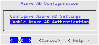
4.6.2 - Enabling/Disabling Azure AD
Using the Enable/Disable Azure AD option, you can enable or disable the Azure AD settings. You can import users or groups and assign roles when you enable the Azure AD settings.
4.7 - Accessing REST API Resources
User authentication is the process of identifying someone who wants to gain access to a resource. A server contains protected resources that are only accessible to authorized users. When you want to access any resource on the server, the server uses different authentication mechanism to confirm your identity.
There are different mechanisms for authenticating and authorizing users in a system. In the ESA, REST API services are only accessible to authorized users. You can authorize or authenticate users using one of the following authentication mechanisms:
- Basic Authentication with username and password
- Client Certificates
- Tokens
4.7.1 - Using Basic Authentication
In the Basic Authentication mechanism, you provide only the user credentials to access protected resources on the server. You provide the user credentials in an authorization header to the server. If the credentials are accurate, then the server provides the required response to access the APIs.
If you want to access the REST API services on ESA, then the IP address of ESA with the username and password must be provided. The ESA matches the credentials with the LDAP or AD. On successful authentication, the roles of the users are verified. The following conditions are checked:
- If the role of the user is Security Officer, then the user can run GET, POST, and DELETE operations on the REST APIs.
- If the role of the user is Security Viewer, then the user can only run GET operation on the REST APIs.
When the Basic Authentication is disabled, then a list of APIs are affected. For more information about the list of APIs, refer here.
The following Curl snippet provides an example to access an API on ESA.
curl -i -X <METHOD> "https://<ESA IP address>:8443/<path of the API>" -d "loginname=<username>&password=<password>"
This command uses an SSL connection. If the server certificates are not configured on ESA, you can append --insecure to the curl command.
For example,
curl -i -X <METHOD> "https://<ESA IP address>:8443/<path of the API>" -d "loginname=<username>&password=<password>" --insecure
You must provide the username and password every time you access the REST APIs on ESA.
4.7.2 - Using Client Certificates
The Client Certificate authentication mechanism is a secure way of accessing protected resources on a server. In the authorization header, you provide the details of the client certificate. The server verifies the certificate and allows you to access the resources. When you use certificates as an authentication mechanism, then the user credentials are not stored in any location.
Note: As a security feature, it is recommended to use the client certificates that are protected with a passphrase.
On ESA, the Client Certificate authentication includes the following steps:
- In the authorization header, you must provide the details, such as, client certificate, client key, and CA certificate.
- The ESA retrieves the name of the user from the client certificate and authenticates it with the LDAP or AD.
- After authenticating the user, the role of that user is validated:
- If the role of the user is Security Officer, then the user can run read and write operations on the REST APIs.
- If the role of the user is Security Viewer, then the user can only run read operations on the REST APIs.
- On successful authentication, you can utilize the API services.
The following Curl snippet provides an example to access an API on ESA.
curl -k https://<ESA IP Address>/<path of the API> -X <METHOD> --key <client.key> --cert <client.pem> --cacert <CA.pem> -v --insecure
You must provide your certificate every time you access the REST APIs on ESA.
4.7.3 - Using JSON Web Token (JWT)
Tokens are reliable and secure mechanisms for authorizing and authenticating users. They are stateless objects created by a server that contain information to identify a user. Using a token, you can gain access to the server without having to provide the credentials for every resource. You request a token from the server by providing valid user credentials. On successive requests to the server, you provide the token as a source of authentication instead of providing the user credentials.
There are different mechanisms for authenticating and authorizing users using tokens. Authentication using JSON Web Tokens (JWT) is one of them. The JWT is an open standard that defines a secure way of transmitting data between two entities as JSON objects.
One of the common uses of JWT is as an API authentication mechanism that allows you to access the protected API resources on your server. You present the JWT generated from the server to access the protected APIs. The JWT is signed using a secret key. Using this secret key, the server verifies the token provided by the client. Any modification to the JWT results in an authentication failure. The information about tokens are not stored on the server.
Only a privileged user can create a JWT. To create a token, ensure that the Can Create JWT Token permission/privilege is assigned to the user role.
The JWT consists of the following three parts:
- Header: The header contains the type of token and the signing algorithm, such as, HS512, HS384, or HS256.
- Payload: The payload contains the information about the user and additional data.
- Signature: Using a secret key, you create the signature to sign the encoded header and payload.
The header and payload are encoded using the Base64Url encoding. The following is the format of JWT:
<encoded header>.<encoded payload>.<signature>
Implementing JWT
On Protegrity appliances, you must have the required authorization to access the REST API services. The following figure illustrates the flow of JWT on the appliances.
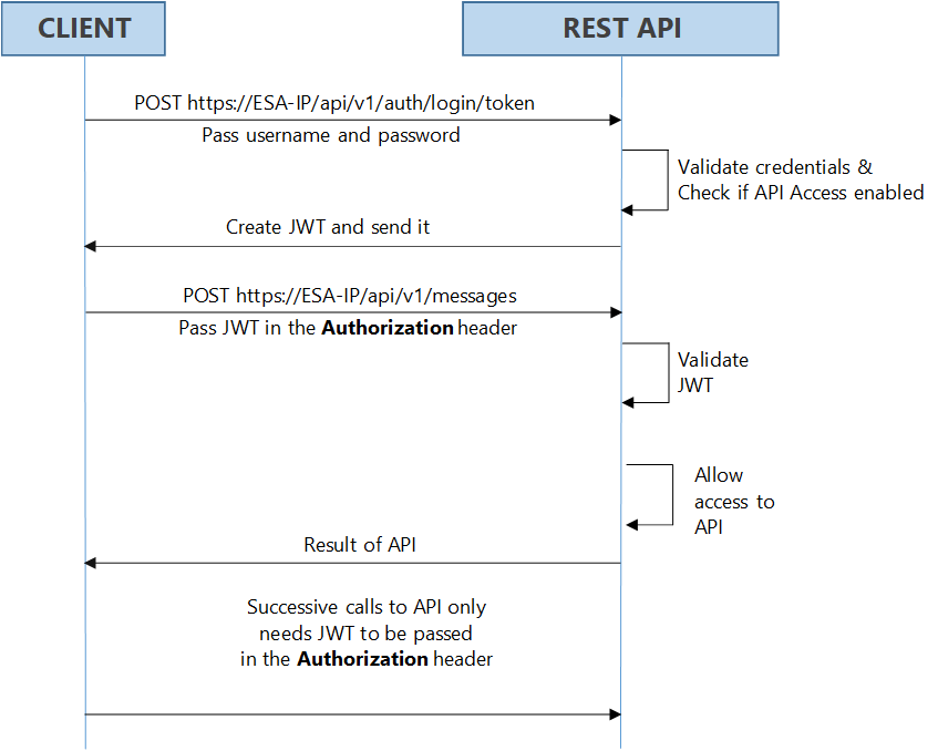
As shown in the figure, login with your credentials to access the API. The credentials are validated against a local or external LDAP. A verification is performed to check the API access for the username. After the credentials are validated, a JWT is created and sent to the user as an authentication mechanism. Using JWT, information can be verified and trusted as it is digitally signed. The JWTs can be signed using a secret with the HMAC algorithm or a private key pair using RSA. After you successfully login using your credentials, a JWT is returned from the server. When you want to access a protected resource on the server, you must send the JWT with the request in the headers.
Working with the Secret Key
The JWT is signed using a private secret key and sent to the client to ensure message is not changed during transmission. The secret key encodes that token sent to the client. The secret key is only known to the server for generating new tokens. The client presents the token to access the APIs on the server. Using the secret key, the server validates the token received by the client.
The secret key is generated when you install or upgrade your appliance. You can change the secret key from the CLI Manager. This secret key is stored in the appliance in a scrambled form.
For more information about setting the secret key, refer to section Configuring JWT
For appliances in a TAC, the secret key is shared between appliances in the cluster. Using the export-import process for a TAC, secret keys are exported and imported between the appliances.
If you want to export the JWT configuration to a file or another machine, ensure that you select the Appliance OS Configuration option, in the Export screen. Similarly, if you want to import the JWT configurations between appliances in a cluster, from the Cluster Export Wizard screen, select the Appliances JWT Configuration check box, under Appliance OS Configuration.
For example, consider ESA 1 and ESA 2 in a TAC setup.
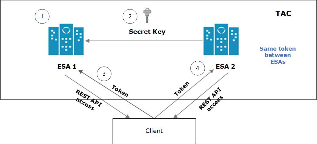
- JWT is created on ESA 1 for appliance using a secret key.
- ESA 1 and ESA 2 are added to TAC. The secret key of ESA 1 is shared with ESA 2.
- Client application requests API access from ESA 1. A JWT is generated and shared with the client application. The client accesses the APIs available in ESA 1.
- To access the APIs of ESA 2, the same token generated by ESA1 is applicable for authentication.
Configuring JWT
You can configure the encoding algorithm, secret key, and JWT token expiry.
To configure the JWT settings:
On the CLI Manager, navigate to Administration > JWT Configuration.
A screen to enter the root credentials appears.
Enter the root credentials and select OK.
The JWT Settings screen appears.
Select Set JWT Algorithm to set the algorithm for validating a token.
The Set JWT Algorithm screen appears.
Select the one of the following algorithms:
- HS512
- HS384
- HS256
Select OK.
Select Set JWT Secret to set the secret key.
The Set JWT Secret screen appears.
Enter the secret key in the New Secret and Confirm Secret fields.
Select OK.
Select Set Token Expiry to set the token expiry period.
In the Set Token Expiry field, enter the token expiry value and select OK.
Select Set Token Expiry Unit to set the unit for token expiry value.
Select second(s), minute(s), hour(s), day(s), week(s), month(s), or year(s) option and select OK.
Select Done.
Refreshing JWT
Tokens are valid for certain period. When a token expires, you must request a new token by providing the user credentials. Instead of providing your credentials on every request, you can extend your access to the server resources by refreshing the token.
In the refresh token process, you request a new token from the server by presenting your current token instead of the username and password. The server checks the validity of the token to ensure that the current token is not expired. After the validity check is performed, a new token is issued to you for accessing the API resources.
In the Protegrity appliances, you can refresh the token by executing the REST API for token refresh.
4.8 - Securing the GRand Unified Bootloader
When a system is powered on, it goes through a boot process before loading the operating system, where an initial set of operations are performed for the system to function normally. The boot process consists of different stages, such as, checking the system hardware, initializing the devices, and loading the operating system.
When the system is powered on, the BIOS performs the Power-On Self-Test (POST) process to initialize the hardware devices attached to the system. It then executes the Master Boot Record (MBR) that contains information about the disks and partitions. The MBR then executes the GRand Unified Bootloader (GRUB).
The GRUB is an operation that identifies the file systems and loads boot images. The GRUB then passes control to the kernel for loading the operating system. The entries in the GRUB menu can be edited by pressing e or c to access the GRUB command-line. Some of the entries that you can modify using the GRUB are listed below:
- Loading kernel images.
- Switching kernel images.
- Logging into single user mode.
- Recovering root password.
- Setting default boot entries.
- Initiating boot sequences.
- Viewing devices and partition, and so on.
In the Protegrity appliances, GRUB version 2 (GRUB 2) is used for loading the kernel. If the GRUB menu settings are modified by an unauthorized user with malicious intent, it can induce threat to the system. Additionally, as per CIS Benchmark, it is recommended to secure the boot settings. Thus, to enhance security of the Protegrity appliances, the GRUB menu can be protected by setting a username and password.
- This feature available only for on-premise installations.
- It is recommended to reset the credentials at regular intervals to secure the system.
The following sections describe about setting user credentials for accessing the GRUB menu on the appliance.
4.8.1 - Enabling the Credentials for the GRUB Menu
You can set a username and password for the GRUB menu from the ESA CLI Manager.
The user created for the GRUB menu is neither a policy user nor an ESA user.
Note: It is recommended you ensure a backup of the system has completed before performing the following operation.
To enable access to GRUB menu:
Login to the ESA CLI manager as an administrative user.
Navigate to Administration > GRUB Credentials Settings.
The screen to enter the root credentials appears.
Enter the root credentials and select OK.
The screen to Grub Credentials screen appears.
Select Enable and press ENTER.
The following screen appears.

Enter a username in the Username text box.
The requirements for the Username are as follows:
- It should contain a minimum of three and maximum of 16 characters
- It should not contain numbers and special characters
Enter a password in the Password and Re-type Password text boxes.
The requirements for the Password are as follows:
- It must contain at least eight characters
- It must contain a combination of alphabets, numbers, and printable characters
Select OK and press ENTER.
A message Credentials for the GRUB menu has been set successfully appears.
Restart the system.
The following screen appears.
Press e or c.
The screen to enter the credentials appears.
Enter the credentials provided in steps 4 and 5 to modify the GRUB menu.
4.8.2 - Disabling the GRUB Credentials
You can disable the username and password that is set for accessing the GRUB menu. When you disable access to the GRUB, then the username and password that are set get deleted. You must enable the GRUB Credentials Settings option and set new credentials to secure the GRUB again.
To disable access to the GRUB menu:
Login to the ESA CLI Manager as an administrative user.
Navigate to Administration > GRUB Credentials Settings.
The screen to enter the root credentials appears.
Enter the root credentials and select OK.
The GRUB credentials screen appears.
Select Disable and press ENTER.
A message Credentials for the GRUB menu has been disabled appears.
4.9 - Working with Installations and Patches
Using the Installations and Patches menu, you can install or uninstall products. You can also view and manage patches from this menu.
4.9.1 - Add/Remove Services
Using Add/Remove Services tool, you can install the necessary products or remove already installed ones, such as, Consul, Cloud-utility product, among others.
To install services:
Login to the ESA CLI Manager.
Navigate to Administration > Installations and Patches > Add/Remove Services.
Enter the root password to execute the install operation and select OK.

Select Install applications and select OK.

Select products to install and select OK.
- If a new product is selected, the installation process starts.
- If the product is already installed, then refer to step 6.
Select an already installed product to upgrade, uninstall, or reinstall, and select OK.
The Package is already installed screen appears. This step is not applicable for the DSG appliance.

Select any one of the following options:
Option Description Upgrade Installs a newer version of the selected product. Uninstall Removes the selected product. Reinstall Removes and installs the product again. Cancel Returns to the Administration menu. Select OK.
4.9.2 - Uninstalling Products
To uninstall products:
Login the ESA CLI Manager.
Proceed to Administration > Installations and Patches > Add or Remove Services.
Enter the root password to execute the uninstall operation and select OK.
Select Remove already installed applications and select OK.
The Select products to uninstall screen appears.
Select the necessary products to uninstall and select OK.
The selected products are uninstalled.
4.9.3 - Managing Patches
You can install and manage your patches from the Patch Management screen.
It allows you to perform the following tasks.
| Option | Description |
|---|---|
| List installed patches | Displays the list of all the patches which are installed in the system |
| Install a patch | Allows you to install the patches |
| Display log | Displays the list of logs for the patches |
Installing Patches
To install a patch:
Log in to the ESA CLI Manager.
Navigate to Administration > Patch Management.
Enter the root password and select OK.
The Patch Management screen appears.
Select Install a patch and select OK.
The Install Patch screen appears.
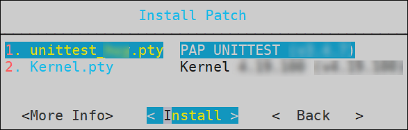
Select the required patch and select Install.
Viewing Patch Information
To view information of a patch:
Login to the ESA CLI Manager.
Navigate to Administration > Patch Management.
Enter the root password and select OK.
Select Install a patch and select OK.
The Install Patch screen appears.
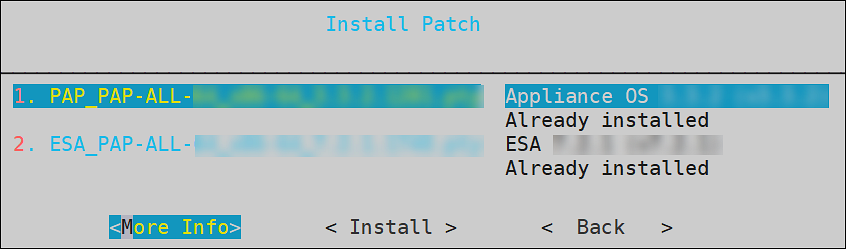
Select the required patch and select More Info.
The information for the selected patch appears.
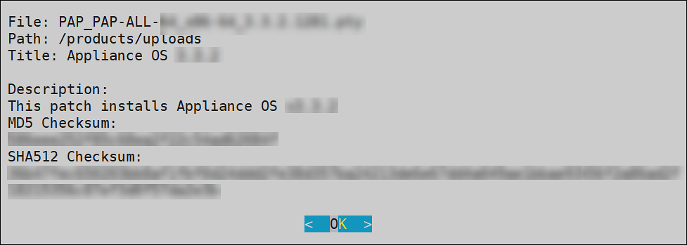
Select OK.
4.10 - Managing LDAP
LDAP is an open industry standard application protocol that is used to access and manage directory information over IP. You can consider it as a central repository of username and passwords, thus providing applications and services the flexibility to validate users by connecting with the LDAP.
The security system of the Appliance distinguishes between two types of users:
End users with specific access or no access to sensitive data. These users are managed through the User Management screen in the Web UI. For more information about user management, refer here.
Administrative users who manage the security policies, for example, “Admin” users who grant or deny access to end users.
In this section, the focus is on managing administrative users. The Administrative users connect to the management interfaces in Web UI or CLI, while the end users connect to the specific security modules they have been allowed access to. For example, a database table may need to be accessed by the end users, while the security policies for access to the table are specified by the Administrative users.
LDAP Tools available in the Administration menu include three tools explained in the following table.
| Tool | Description |
|---|---|
| Specify LDAP Server | Reconfigure all client-side components to use a specific LDAP. To authenticate users, the data security platform supports three modes for integration with directory services: Protegrity LDAP Server, Proxy Authentication, and Local LDAP Server. - Protegrity LDAP: In this mode, all administrative operations such as policy management, key management, etc. are handled by users that are part of the Protegrity LDAP. This mode can be used to configure or authenticate with either local or remote appliance product. - Proxy Authentication: In this mode, you can import users from an external LDAP to ESA. ESA is responsible for authorization of users, while the external LDAP is responsible for authentication of users. - Reset LDAP Server Settings: In this mode, an administrative user can reset the configuration to the default configuration using admin credentials. |
| Configure Local LDAP settings | Configure your LDAP to be accessed from the other machines. |
| Local LDAP Monitor | Examine how many LDAP operations per second are running. |
4.10.1 - Working with the Protegrity LDAP Server
Every appliance includes an internal directory service. This service can be utilized by other appliances for user authentication.
For example, a DSG instance might utilize the ESA LDAP for user authentication. In such cases, you can configure the LDAP settings of the DSG in the Protegrity LDAP Server screen. In this screen, you can specify the IP address of the ESA with which you want to connect.
You can add IP addresses of multiple appliances to enable fault tolerance. In this case, if connection to the first appliance fails, connection is transferred to next appliance in the list.
If you are adding multiple appliances in the LDAP URI, ensure that the values of the Bind DN, Bind Password, and Base DN is same for all the appliances in the list.
To specify Protegrity LDAP server:
Login to the Appliance CLI Manager.
Navigate to Administration > Specify LDAP Server.
Enter the root password and select OK.
In the LDAP Server Type screen, select Protegrity LDAP Server and select OK.
The following screen appears.

Enter information for the following fields.
Table 1. LDAP Server Settings
Setting Description LDAP URI Specify the IP address of the LDAP server you want to connect to in the following format. ldap://host:port. You can configure to connect Protegrity Appliance LDAP. For example,ldap://192.168.3.179:389.For local LDAP, enter the following IP address:ldap://127.0.0.1:389.If you specify multiple appliances, ensure that the IP addresses are separated by the space character.For example,ldap://192.1.1.1 ldap://10.1.0.0 ldap://127.0.0.1:389Base DN The LDAP Server Base distinguished name. For example: ESA LDAP Base DN: dc=esa,dc=protegrity,dc=com.Group DN Distinguished name of the LDAP Server group container. For example: ESA LDAP Group DN:ou=groups,dc=esa,dc=protegrity,dc=com.Users DN Distinguished name of the user container. For example: ESA LDAP Users DN:ou=people,dc=esa,dc=protegrity,dc=com.Bind DN Distinguished name of the LDAP Bind User. For example: ESA LDAP Bind User DN cn=admin, ou=people, dc=esa, dc=protegrity, dc=com.Bind Password The password of the specified LDAP Bind User. If you modify the bind user password, ensure that you use the Specify LDAP Server tool to update the changes in the internal LDAP.Bind UserThe bind user account password allows you to specify the user credentials used for LDAP communication. This user should have full read access to the LDAP entries in order to obtain accounts/groups/permissions.If you are using the internal LDAP, and you change the bind username/password, using Change a directory account option, then you must update the actual LDAP user. Make sure that a user with the specified username/password exists. Run Specify LDAP Server tool with the new password to update all the products with the new password. Refer to section Protegrity LDAP Server for details.Click Test to test the connection.
If the connection is established, then a Successfully Done message appears.
4.10.2 - Changing the Bind User Password
The following section describe the steps to change the password for the ldap_bind_user using the CLI manager.
To change the ldap_bind_user password:
Login to the ESA CLI Manager.
Navigate to Administration > Specify LDAP server/s.
Enter the root password and select OK.
Select Reset LDAP Server settings and select OK.
The following screen appears.
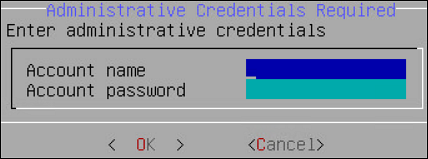
Enter the admin username and password and select OK.
The following screen appears.
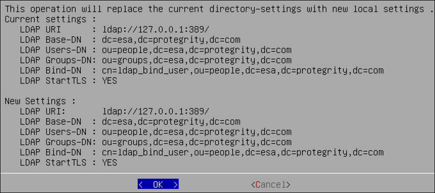
Select OK.
The following screen appears.
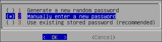
Select Manually enter a new password and select OK.
The following screen appears.
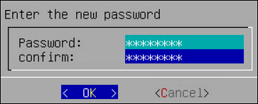
Enter the new password, confirm it, and select OK.
The following screen appears.
Select OK.
The password is successfully changed.
4.10.3 - Working with Proxy Authentication
Simple Authentication and Security Layer (SASL) is a framework that provides authentication and data security for Internet protocols. The data security layer offers data integrity and confidentiality services. It provides a structured interface between protocols and authentication mechanisms.
SASL enables ESA to separate authentication and authorization of users. The implementation is such that when users are imported, a user with the same name is recreated in the internal LDAP. When the user accesses the data security platform, ESA authorizes the user and communicates with the external LDAP for authenticating the user. This implementation ensures that organizations are not forced to modify their LDAP configuration to accommodate the data security platform. SASL is referred to as Proxy authentication in ESA CLI and Web UI.
To enable proxy authentication:
Login to the Appliance CLI Manager.
Navigate to Administration > LDAP Tools > Specify LDAP Server.
Enter the root password and select OK.
Select Set Proxy Authentication.
Specify the LDAP Server settings for proxy authentication with the external LDAP as shown in the following figure.

For more information about the LDAP settings, refer to Proxy Authentication Settings.
Select Test to test the settings provided. Select Test to test the settings provided. When Test is selected, ESA verifies if the connection to the external LDAP works, as per the Proxy Authentication settings provided.
The Bind Password is required when Bind DN is provided message appears.
Select OK.
Enter the LDAP user name and password provided as the bind user.
You can provide username and password of any other user from the LDAP as long as the LDAP Filter field exists in both the bind user name and any other user.
A Testing Proxy Authentication-Completed successfully message appears.
Select OK in the following message screen.
The following confirmation message appears.
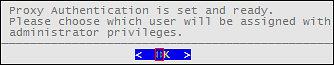
Select Apply to apply the settings. In ESA CLI, only one user is allowed to be imported. This user is granted admin privileges, such that importing users and managing users can be performed by the user in the User Management screen. The User Management Web UI is used to import users from the external LDAP.
In the Select user to grant administrative privileges screen, select a user and confirm selection.
In the Setup administrator privileges screen, enter the ESA admin user name and password and select OK.
The following message appears.
Navigate to Administration > Services to verify that the Proxy Authentication Service is running.
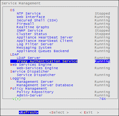
4.10.4 - Configuring Local LDAP Settings
The local LDAP settings are enabled on port 389 by default.
To specify local LDAP server configuration:
Login to the ESA CLI Manager.
Navigate to Administration > Configure local LDAP settings.
Enter the root password and select OK.
The following screen appears.

In the LDAP listener IP address field, enter the LDAP listener IP address for local access. By default, it is 127.0.0.1.
In the LDAPS (SSL) listener IP address field, enter the LDAPS SSL listener IP address for remote access. It is 0.0.0.0 or a specific valid address for your remote LDAP directory.
Select OK.
4.10.5 - Monitoring Local LDAP
Local LDAP Monitor tool allows you to examine, in real time, how many LDAP operations per second are currently running, which is very useful to enhance the performance. You can use this tool to monitor the following tasks:
- Check LDAP Connectivity for LDAP Bind and LDAP Search.
- Modify or optimize LDAP cache, threading, and memory settings to improve performance and remove bottlenecks.
- Measure “number of changes” and “last modified date and time” on the LDAP server, which can be useful, for example, for verifying export/import operations.

4.10.6 - Optimizing Local LDAP Settings
When the Local LDAP receives excessive requests, the requests are cached. However, if the the cache is overloaded, it causes the LDAP to become unresponsive. From v9.1.0.3, a standard set of values for the cache that is required for optimal handling of the LDAP requests is set in the system. After you upgrade to v9.1.0.3, you can tune the cache parameters for the Local LDAP configuration. The default values for the cache parameters is shown in the following list.
- The slapd.conf file in the /etc/ldap directory contains the following cache values:
- cachesize 10000 (10,000 entries)
- idlcachesize 30000 (30,000 entries)
- dbconfig set_cachesize 0 209715200 0 (200 MB)
- The DB_CONFIG file in the /opt/ldap/db* directory contains the following the cache values:
- set_cachesize 0 209715200 0 (200 MB)
Based on the setup and the environment in the organization, you can choose to increase the parameters.
Ensure that you back up the files before editing the parameters.
- On the CLI Manager, navigate to Administration > OS Console.
- Edit the values for the required parameters.
- Restart the slapd service using the /etc/init.d/slapd restart command.
4.11 - Rebooting and Shutting down
You can reboot or shut down your appliance if necessary using Administration > Reboot and Shutdown. Make sure the Data Security Platform users are aware that the system is being rebooted or turned off and no important tasks are being performed at this time.
Cloud platforms and power off
For cloud platforms, it is recommended to shut down or power off the CLI Manager or Appliance Web UI. With cloud platforms, such as Azure, AWS, or GCP, the instances run the appliance.
4.12 - Accessing the OS Console
You can access OS console using Administration > OS Control. You require root user credentials to access the OS console.
If you have System Monitor settings enabled in the Preferences menu, then the OS console will display the System Monitor screen upon entering the OS console.
To enable the System Monitor setting:
Login to the ESA CLI Manager.
Navigate to Preferences.
Enter the root password and select OK.
The Preferences screen appears.
Select Show System-Monitor on OS-Console.
Press Select.
Select Yes and select OK.
Select Done.
5 - Working with Networking
Networking Management allows configuration of the ESA network settings such as, host name, default gateway, name servers, and so on. You can also configure SNMP settings, network bind services, and network firewall.
From the ESA CLI Manager, navigate to Networking to manage your network settings.
The following figure shows the Networking Management screen.

| Option | Description |
|---|---|
| Network Settings | Customize the network configuration settings for your appliance. |
| SNMP Configuration | Allow a remote machine to query different performance status of the appliance, such as start the service, set listening address, show or set community string, or refresh the service. |
| Bind Services/ Addresses | Specify the network address or addresses for management and Web Services. |
| Network Troubleshooting Tools | Troubleshoot network and connectivity problems using the following Linux commands – Ping, TCPing, TraceRoute, MTR, TCPDump, SysLog, and Show MAC. |
| Network Firewall | Customize firewall rules for the network traffic. |
5.1 - Configuring Network Settings
When this option is selected, network configuration details added during installation are displayed. The network connection for the appliance are displayed. You can modify the network configuration as per the requirements.

Changing Hostname
The hostname of the appliance can be changed.Ensure that the hostname does not contain the dot(.) special character.
To change the hostname:
Login to the Appliance CLI Manager.
Navigate to Networking > Network Settings.
Select Hostname and select Edit.
In the Set Hostname field, enter a new hostname.
Select OK.
The hostname is changed.
Configuring Management IP Address
You can configure the management IP address for your appliance from the networking screen.
To configure the management IP address:
Login to the Appliance CLI Manager.
Navigate to Networking > Network Settings.
Select Management IP and select Edit.
In the Enter IP field, enter the IP address for the management NIC.
In the Enter Netmask field, enter the subnet for the management NIC.
Select OK.
The management IP is configured.
Configuring Default Route
The default route is a setting that defines the packet forwarding rule for a specific route. This parameter is required only if the appliance is on a different subnet than the Web UI or for the NTP service connection. If necessary, then request the default gateway address from your network administrator and set this parameter accordingly.
The default route is a setting that defines the packet forwarding rule for a specific route. The default route is the first IP address of the subnet for the management interface.
To configure the default route:
Login to the Appliance CLI Manager.
Navigate to Networking > Network Settings.
Select Default Route and press Edit.
Enter the default route and select Apply.
Configuring Domain Name
You can configure the domain name for your appliance from the networking screen.
To configure the domain name:
Login to the Appliance CLI Manager.
Navigate to Networking > Network Settings.
Select Domain Name and select Edit.
In the Set Domain Name field, enter the domain name.
Select Apply.
The domain name is configured.
Configuring Search Domain
You can configure a domain name that is used as in the domain search list.
To configure the search domain:
Login to the Appliance CLI Manager.
Navigate to Networking > Network Settings.
Select Search Domains and select Edit.
In the Search Domains dialog box, select Edit.
In the Edit search domain field, enter the domain name and select OK.
Select Add to add another search domain.
Select Remove to remove a search domain.
Configuring Name Server
You can configure the IP addresses for your domain name.
To configure the domain IP address:
Login to the Appliance CLI Manager.
Navigate to Networking > Network Settings.
Select Name Servers and select Edit.
In the Domain Name Servers dialog box, select Edit to modify the server IP address.
Select Remove to delete the domain IP address.
Select Add to add another domain IP address.
In the Add new nameserver field, enter the domain IP address and select OK.
The IP address for the domain is configured.
Assigning a Default Gateway to the NIC
To assign a default gateway to the NIC:
Login to the Appliance CLI Manager.
Navigate to Networking > Network Settings.
Select Interfaces and select Edit.
The Network Interfaces dialog box appears.
Select the interface for which you want to add a default gateway.
Select Edit.
Select Gateway.
The Gateway Settings dialog box appears.
In the Set Default Gateway for Interface ethMNG field, enter the Gateway IP address and select Apply.
Selecting Management NIC
When you have multiple NICs, you can specify the NIC that functions as a management interface.
To select the management NIC:
Login to the Appliance CLI Manager.
Navigate to Networking > Network Settings.
Select Management interface and select Edit.
Select the required NIC.
Select Select.
The management NIC is changed.
Changing the Management IP on ethMNG
Follow these instructions to change the management IP on ethMNG. Be aware, changes to IP addresses are immediate. Any changes to the management IP, on ethMNG, while you are connected to CLI Manager or Web UI will cause the session to disconnect.
To change the management IP on ethMNG:
Login to the Appliance CLI Manager.
Navigate to Networking > Network Settings.
Select Interfaces and select Edit.
The Network Interfaces screen appears.
Select ethMNG and click Edit.
Select the network type and select Update.
In the Interface Settings dialog box, select Edit.
Enter the IP address and net mask.
Select OK.
At the prompt, press ENTER to confirm.
The IP address is updated, and the Address Management screen appears.
Identifying an Interface
To identify an interface:
Login to the Appliance CLI Manager.
Navigate to Networking > Network Settings.
Select Interfaces and select Edit.
The Network Interfaces screen appears.
Select the network interface and select Blink.
This causes an LED on the NIC to blink and the Network Interfaces screen appears.
Adding a service interface address
From ESA v9.0.0.0, the default IP addresses assigned to the docker interfaces are between 172.17.0.0/16 and 172.18.0.0/16. Ensure that the IP addresses assigned to the docker interface must not conflict with your organization’s private/internal IP addresses.
For more information about reconfiguring the docker interface addresses, refer to Configuring the IP address for the Docker Interface.
Be aware, changes to IP addresses are immediate.
To add a service interface address:
Login to the Appliance CLI Manager.
Navigate to Networking > Network Settings.
Select Interfaces and select Edit.
The Network Interfaces screen appears.
Navigate to the service interface to which you want to add an address and select Update.
Select Add.
At the prompt, type the IP address and the netmask.
Press ENTER.
The address is added, and the Address Management screen appears.
5.2 - Configuring SNMP
The Simple Network Management Protocol (SNMP) is used for monitoring appliances in a network. It consists of two entities, namely, an agent and a manager that work in a client-server mode. The manager performs the role of the server and agent acts as the client. Managers collect and process information about the network provided by the client. For more information about SNMP, refer to the following link.
In Protegrity appliances, you can use this protocol to query the performance figures of an appliance. Typically, the ESA acts as a manager that monitors other appliances or Linux systems on the network. In ESA, the SNMP can be used in the following two methods:
snmpd: The snmpd is an agent that waits for and responds to requests sent by the SNMP manager. The requests are processed, the necessary information is collected, the requested operation is performed, and the results are sent to the manager. You can run basic SNMP commands, such as, snmpstart, snmpget, snmpwalk, snmpsync, and so on. In a typical scenario, an ESA monitors and requests a status report from another appliance on the network, such as, DSG or ESA. By default, the snmpd requests are communicated over the UDP port 161.
In the Appliance CLI Manager, navigate to Networking > SNMP Configuration > Protegrity SNMPD Settings to configure the snmpd settings. The snmpd.conf file in the /etc/snmp directory contains the configuration settings of the SNMP service.

snmptrapd: The snmptrapd is a service that sends messages to the manager in the form of traps. The SNMP traps are alert messages that are configured in the manager in a way that an event occurring at the client immediately triggers a report to the manager. In a typical scenario, you can create a trap in ESA to cold-start a system on the network in case of a power issue. By default, the snmptrapd requests are sent over the UDP port 162. Unlike snmpd, in the snmptrapd service, the agent proactively sends reports to the manager based on the traps that are configured.
In the CLI Manager, navigate to Networking > SNMP Configuration > Protegrity SNMPTRAPD Settings to configure the snmptrapd settings. The snmptrapd.conf file in the /etc/snmp directory can be edited to configure SNMP traps on ESA.

The following table describes the different settings that you configure for snmpd and snmptrapd services.
| Setting | Description | Applicable to SNMPD | Applicable to SNMPTRAPD | Notes |
| Managing service | Start, stop, or restart the service | ✓ | ✓ | Ensure that the SNMP service is running. On the Web UI, navigate to System → Services tab to check the status of the service. |
| Set listening address | Set the port to accept SNMP requests | ✓ | ✓ |
NoteYou can change the listening address only
once. |
| Set DTLS/TLS listening port | Configure SNMP on DTLS over UDP or SNMP on TLS over TCP | ✓ | The default listening port for SNMPD is set to
TCP 10161. | |
| Set community string | String comprising of user id and password to access the statistics of another device | ✓ |
The SNMPv1 is used as default a protocol, but you can also configure SNMPv2 and SNMPv3 to monitor the status and collect information from network devices. The SNMPv3 protocol supports the following two security models:
- User Security Model (USM)
- Transport Security Model (TSM)
5.2.1 - Configuring SNMPv3 as a USM Model
Configuring SNMPv3 as a USM Model:
From the CLI manager navigate to Administration > OS Console.
The command prompt appears.
Perform the following steps to comment the rocommunity string.
Edit the snmpd.conf using a text editor.
/etc/snmp/snmpd.confPrepend a # to comment the rocommunity string.
Save the changes.
Run the following command to set the path for the snmpd.conf file.
export datarootdir=/usr/shareStop the SNMP daemon using the following command:
/etc/init.d/snmpd stopAdd a user with read-only permissions using the following command:
net-snmp-create-v3-user -ro -A <authorization password> -a MD5 -X <authorization password> -x DES snmpuserFor example,
net-snmp-create-v3-user -ro -A snmpuser123 -a MD5 -X snmpuser123 -x DES snmpuserStart the SNMP daemon using the following command:
/etc/init.d/snmpd startVerify if SNMPv1 is disabled using the following command:
snmpwalk -v 1 -c public <hostname or IP address>Verify if SNMPv3 is enabled using the following command:
snmpwalk -u <username> [-A (authphrase)] [-a (MD5|SHA)] [-x DES] [-X (privaphrase)] (ipaddress)[:(dest_port)] [oid]For example,
snmpwalk -u snmpuser -A snmpuser123 -a MD5 -X snmpuser123 -x DES -l authPriv 127.0.0.1 -v3Unset the variable assigned to the snmpd.conf file using the following command.
unset datarootdir
5.2.2 - Configuring SNMPv3 as a TSM Model
Configuring SNMPv3 as a TSM Model:
From the CLI manager navigate to Administration > OS Console.
The command prompt appears.
Set up the CA certificates, Server certificates, Client certificates, and Server key on the server using the following commands:
ln -s /etc/ksa/certificates/CA.pem /etc/snmp/tls/ca-certs/CA.crt

ln -s /etc/ksa/certificates/server.pem /etc/snmp/tls/certs/server.crt

ln -s /etc/ksa/certificates/client.pem /etc/snmp/tls/certs/client.crt

ln -s /etc/ksa/certificates/mng/server.key /etc/ksa/certificates/server.key
Change the mode of the server.key file under /etc/ksa/certificates/ directory to read only using the following command:
chmod 600 /etc/ksa/certificates/server.keyEdit the snmpd.conf file under /etc/ksa directory.
Append the following configuration in the snmpd.conf file.
[snmp] localCert server
[snmp] trustCert CA
certSecName 10 client --sn <username>
Trouser -s tsm "< username>" AuthPriv
Alternatively, you can also use a field from the certificate using the –-cn flag as a username as follows:
certSecName 10 client –cn
Trouser –s tsm “Protegrity Client” AuthPriv
To use fingerprint as a certificate identifier, execute the following command:
net-snmp-cert showcerts --fingerprint
11`
Restart the SNMP daemon using the following command:
/etc/init.d/snmpd restartYou can also restart the SNMP service using the ESA Web UI.
Deploy the certificates on the client side.
5.3 - Working with Bind Services and Addresses
The Bind Services/Addresses tool allows for separating the Web services from their management, Web UI and SSH. You can specify the network cards that will be used for Web management and Web services. For example, the DSG appliance uses the ethMNG interface for Web UI and the ethSRV interface for enabling communication with different applications in an enterprise. This article provides instructions for selecting network interfaces for management and services.
Ensure that all the NICs added to the appliance are configured in the Network Settings screen.
5.3.1 - Binding Interface for Management
If you have multiple NICs, you can specify the NIC that functions as a management interface.
To bind the management NIC:
Login to the CLI Manager.
Navigate to Networking > Bind Services/Address.
Enter the root password and select OK.

Select Management and choose Select.
In the interface for ethMNG, select OK.
Choose Select and press ENTER.
The NIC for Management is assigned.
Select Done.
A message Successfully done appears and the NIC for service requests are assigned.
Navigate to Administration > OS Console.
Enter the root password and select OK.
Run the
netstat -tunlpcommand to verify the status of the NICs.
5.3.2 - Binding Interface for Services
If you have multiple service NICs, you can specify the NICs that will function to accept the Web service requests on port 8443.
To bind the service NIC:
Login to the CLI Manager.
Navigate to Networking > Bind Services/Address.
Enter the root password and select OK.
Select Service and choose Select.
A list of service interfaces with their IP addresses is displayed.
Select the required interface(s) and select OK.
The following message appears.

Choose Yes and press ENTER.
Select Done.
A message Successfully done appears and the NIC for service requests are assigned.
Navigate to Administration > OS Console.
Enter the root password and select OK.
Run the
netstat -tunlpcommand to verify the status of the NICs.
5.4 - Using Network Troubleshooting Tools
Using the Network Troubleshooting Tools, you can check the health of your network and troubleshoot problems. This tool is composed of several utilities that allow you to test the integrity of you network. The following table describes the utilities that make up the Network Utilities tool.
Table 1. Network Utilities
Name | Using this tool you can... | How… |
Ping | Tests whether a specific Host is accessible across the
network. | In the Address field, type the IP
address that you want to test. Press
ENTER. |
TCPing | Tests whether a specific TCP port on a Host is
accessible across the network. | In the Address field, type the IP
address. In the Port field, type the
port number. Select OK. |
TraceRoute | Tests the path of a packet from one machine to another.
Returns timing information and the path of the packet. | At the prompt, type the IP address or Host name of the
destination machine. Select
OK. |
MTR | Tests the path of a packet and returns the list of
routers traversed and some statistics about each. | At the prompt, type the IP address or Host
name. Select OK. |
TCPDump | Tests network traffic, and examines all packets going
through the machine. | To filter information, by network interface, protocol,
Host, or port, type the criteria in the corresponding text
boxes. Select OK. |
SysLog | Sends syslog messages. Can be used to test syslog
connectivity. | In the Address field, enter the
IP address of the remote machine the syslogs will be sent
to. In the Port field, enter a port
number the remote machine is listening to. In the
Message field, enter a test message. Select
OK. On the remote machine, check if
the syslog was successfully sent. Note that the appliance
uses UDP syslog, so there is no way to validate whether the syslog
server is accessible. |
Show MAC | Finds out the MAC address for a given IP address.
Detects IP collision. | At the prompt, type the IP address or Host
name. Select OK. |
5.5 - Managing Firewall Settings
Protegrity internal firewall provides a way to allow or restrict inbound access from the outside to Protegrity Appliances. Using the Network Firewall tool you can manage your Firewall settings. For example, you can allow access to the management-network interface only from a specific machine while denying access to all other machines.
To improve security in the ESA, the firewall in v9.2.0.0 is upgraded to use the nftables framework instead of the iptables framework. The nftables framework helps remedy issues, including those relating to scalability and performance.
The iptables framework allows the user to configure IP packet filter rules. The iptables framework has multiple pre-defined tables and base chains, that define the treatment of the network traffic packets. With the iptables framework, you must configure every single rule. You cannot combine the rules because they have several base chains.
The nftables framework is the successor of the iptables framework. With the nftables framework, there are no pre-defined tables or chains that define the network traffic. It uses simple syntax, combines multiple rules, and one rule can contain multiple actions. You can export the data related to the rules and chains to json or xml using the nft userspace utility.
Verifying the nftables
This section provides the steps to verify the nftables.
To verify the nftables:
Log in to the CLI Manager.
Navigate to Administration > OS Console.
Enter the root password and select OK.
Run the command
nft list ruleset.
The nftables rules appear.
Listing the Rules
Using the Rules List option, you can view the available firewall rules.
To view the details of the rule:
Log in to the CLI Manager.
Navigate to Networking > Network Firewall.
Enter the root password and select OK.
The following screen appears.

From the menu, select Rules List to view the list of rules.
A list of rules appear.
Select a rule from the list and click More.
The policy, protocol, source IP address, interface, port, and description appear.
Click Delete to delete a selected rule. Once confirmed, the rule is deleted.
Log in to the Web UI.
Navigate to System > Information to view the rules.
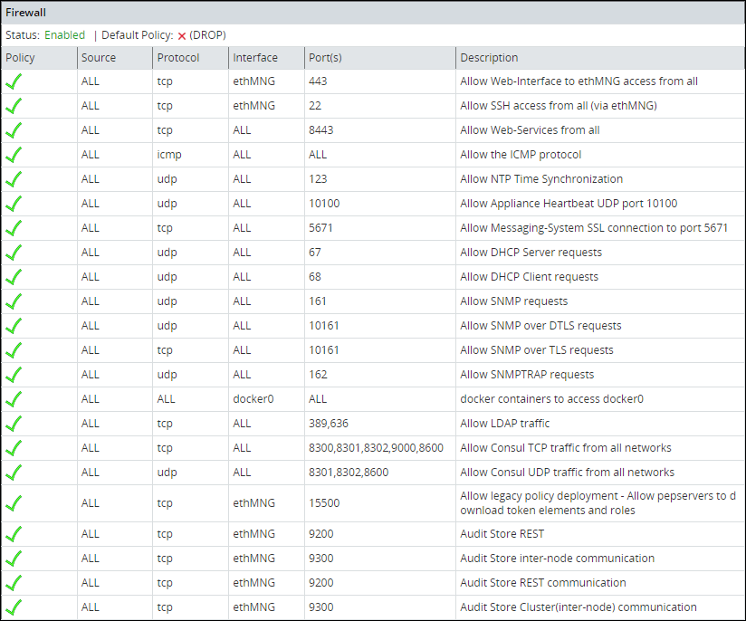
Reordering the Rules List
Using the Reorder Rules List option, you can reorder the list of rules. With buttons Move up and Move down you can move the selected rule. When done, click Apply for the changes to take effect.
The order of the specified rules are important. When reordering the firewall rules, take into account that rules which are in the beginning of the list are of the first priority. Thus, if there are conflicting rules in the list, the one which is the first in the list is applied.
Specifying the Default Policy
The default policy determines what to do on packets that do not match any existing rule. Using the Specify Default Policy option, you can set the default policy for the input chains. You can specify one of the following options:
- Accept - Let the traffic pass through.
- Drop - Remove the packet from the wire and generate no error packet.
If not specified by any rule, then the incoming packet will be dropped as the default policy. If specified by a rule, then the incoming packet will be allowed/denied or dropped depending on the policy of the rule.
Adding a New Rule
Every new rule specifies the criteria for matching packets and the action required. You can add a new rule using the Add New Rule option. This section explains how to add a firewall rule.
Adding a new rule is a multi-stage process that includes:
- Specifying an action to be taken for matching incoming traffic:
- Accept - Allow the packets.
- Drop - Remove the packet from the wire and generate no error packet.
- Reject - Remove the packet from the wire and return an error packet.
- Specifying the local service for this rule.
- Specifying the local network interface. It can be any or selected interface..
- Specifying the remote machine criteria.
- Providing a description for the rule. This is optional.
When a Firewall rule is added, it is added to the end of the Firewall list. If there is a conflicting rule in the beginning of the list, then the new rule may be ignored by the Firewall. Thus, it is recommended to move the new rule somewhere to the beginning of the Firewall rules list.
Adding a New Rule with the Predefined List of Functionality
Follow these instructions to add a new rule with the predefined list of functionality:
Select a policy for the rule, accept, drop, or reject, which will define how a package from the specific machine will be treated by the appliance Firewall.
Click Next.
Specify what will be affected by the rule. Two options are available: to specify the affected functionality list, in this case, you do not need to specify the ports since they are already predefined, or to specify the protocol and the port.
Select the local service affected by the rule. You can select one or more items to be affected by the firewall rule.
Click Next.
If you want to have a number of similar rules, then you can specify multiple items from the functionality list. Thus, for example, if you want to allow access from a certain machine to the appliance LDAP, SNMP, High Availability, SSH Management, or Web Services Management, you can specify these items in the list.
Click Manually.
In the following dialog box, select a protocol for the rule. You can select between TCP, UDP, ICMP, or any.
In the following screen, specify the port number and click Next.
In the following screen you are prompted to specify an interface. Select between ethMNG (Ethernet management interface), ethSRV0 (Ethernet security service interface), ethSRV1, or select Any.
In the following screen you are prompted to specify the remote machine. You can specify between single/IP with subnet or domain name.
When you select Single, you will be asked to specify the IP in the following screen.
When you select IP with Subnet, you will be asked to specify the IP first, and then to specify the subnet.
When you select Domain Name, you will be asked to specify the domain name.
When you have specified the remote machine, the Summary screen appears. You can enter the description of your rule if necessary.
Click Confirm to save the changes.
Click OK in the confirmation message listing the rules that will be added to the Rules list.
Disabling/Enabling the Firewall Rules
Using the Disable/Enable Firewall option, you can start your firewall. All rules that are available in the firewall rules list will be affected by the firewall when it is enabled. All new rules added to the list will be affected by the firewall. You can also restart, start, or stop the firewall using ESA Web UI.
Resetting the Firewall Settings
Using the Reset Firewall Settings option, you can delete all firewall rules. If you use this option, then the firewall default policy becomes accept and the firewall is enabled.
If you require additional security, then change the default policy and add the necessary rules immediately after you reset the firewall.
5.6 - Using the Management Interface Settings
Using the Management Interface Settings option, you can specify the network interface that will be used for management (ethMNG). By default, the first network interface is used for management (ethMNG). The first management Ethernet is the one that is on-board.

If you change the network interface, then you are asked to reboot the ESA for the changes to take effect.
Note: The MAC address is stored in the appliance configuration. If the machine boots or reboots and this MAC address cannot be found, then the default, which is the first network card, will be applied.
5.7 - Ports Allowlist
On the Proxy Authentication screen of the Web UI, you can add multiple AD servers for retrieving users. The AD servers are added as URLs that contain the IP address/domain name and the listening port number. You can restrict the ports on which the LDAP listens to by maintaining a port allowlist. This ensures that only those ports that are trusted in the organization are mentioned in the URLs.
On the CLI Manager, navigate to Networking > Ports Allowlist to set a list of trusted ports. By default, port 389 is added to the allowlist.
The following figure illustrates the Ports Allowlist screen.

This setting is applicable only to the ports entered in the Proxy Authentication screen of the Web UI.
Viewing list of allowed ports
You can view the list of ports that are specified in the allowlist.
On the CLI Manager, navigate to Networking > Ports Allowlist.
Enter the root credentials.
Select List allowed ports.
The list of allowed ports appears.
Adding ports to the allowlist
Ensure that multiple port numbers are comma-delimited and do not contain space between them.
On the CLI Manager, navigate to Networking > Ports Allowlist.
Enter the root credentials.
Select Add Ports.
Enter the required ports and select OK.
A confirmation message appears.
6 - Working with Tools
Protegrity appliances are equipped with a Tools menu. The following sections list and explain the available tools and their functionalities.

6.1 - Configuring the SSH
The SSH Configuration tool provides a convenient way to examine and manage the SSH configuration that would fit your needs. Changing the SSH configuration may be necessary for special needs, troubleshooting, or advanced non-standard scenarios. By default, the SSH is configured to deny any SSH communication with unknown remote servers. You can allow the authorized users with keys to communicate without passwords. Every time you add a remote host, the system obtains the SSH key for this host, and adds it to the known hosts.
Note: It is recommended to create a backup of the SSH settings/keys before you make any modifications.
For more information for Backup from CLI, refer to here.
For more information for Backup from Web UI, refer to here.
Using Tools > SSH Configuration, you can:
- Specify SSH Mode.
- Specify SSH configuration.
- Manage the hosts that the Appliance can connect to.
- Set the authorized keys.
- Manage the keys that belong to local accounts.
- Generate new SSH server keys.

6.1.1 - Specifying SSH Mode
Using SSH Mode tool, you can set restrictions for SSH connections. The restrictions can be hardened or made slack according to your needs. Four modes are available, as described in the following table:
| Mode | SSH Server | SSH Client |
|---|---|---|
| Paranoid | Disable root access | Disable password authentication, allows to connect only using public keys. Block connections to unknown hosts. |
| Standard | Disable root access | Allow password authentication. Allow connections to new or unknown hosts, enforce SSH fingerprint of known hosts. |
| Open | Allow root access Accept connections using passwords and public keys | Allow password authentication. Allow connection to all hosts – do not check hosts fingerprints. |
6.1.2 - Setting Up Advanced SSH Configuration
A user with administrative credentials can configure the SSH idle timeout and client authentication settings. The following screen shows the Advanced SSH Configuration.

In the Idle Timeout field, enter the idle timeout period in seconds. This allows the user to set idle timeout period for the SSH server before logout.
When you are working on the OS Console using the OpenSSH session, if the session is idle for the specified time, then the OS Console session gets closed. However, you are re-directed to the Administration screen.
In the Client Authentications field, specify the order for trying the SSH authentication method. This allows you to prefer one method over another. The default for this option is publickey, password.
6.1.3 - Managing SSH Known Hosts
Using Known Hosts: Hosts I can connect to, you can manage the hosts that you can connect to using SSH. The following table explains the options in the Hosts that I connect to dialog box:
| Using… | You can… |
|---|---|
| Display List | View the list of SSH allowed hosts you can connect to. |
| Reset List | Clear the SSH allowed hosts list. Only the local host, which is the default, appears. |
| Add Host | Add a new SSH allowed host. |
| Delete Host | Delete a host from the list of SSH allowed hosts. |
| Refresh (Sync) Host | Make sure that the available key is a correct key from each IP. To do this, go to each IP/host and re-obtain its key. |
6.1.4 - Managing Authorized Keys
SSH Authorized keys are used to specify SSH keys that are allowed to connect to this machine without entering the password. The system administrator can create such SSH keys and import the keys to this appliance. This is a standard SSH mechanism to allow secured access to machines without a need to enter a password.
Using the Authorized Keys tool, you can display the keys and delete the list of authorized keys from the Reset List option. This would reject all incoming connections that used the authorized keys reset with this tool.
Examine and manage the users that are authorized to access this host.
6.1.5 - Managing Identities
Using the Identities menu, you can manage and examine which users can start SSH communication from this host using SSH keys. You can:
- Display the list of such keys that already exist.
- Reset the SSH keys. This means that all SSH keys used for outgoing connections are deleted.
- Add an identity from the list already available by default or create one as required, using the Directory or Filter options.
- Delete an identity. This should be done with extreme care.
6.1.6 - Generating SSH Keys
Using the Generate SSH Keys, you can create new SSH keys. If you recreate the SSH Keys, then the remote machines that store the current SSH key, will not be able to contact the appliance until you manually update the SSH keys on those machines.
6.1.7 - Configuring the SSH
SSH is a network protocol that ensures a secure communication over an unsecured network. It comprises of a utility suite which provides high-level authentication encryption over unsecured communication channels. SSH utility suites provide a set of default rules that ensure the security of the appliances. These rules consist of various configurations such as password authentication, log level info, port numbers info, login grace time, strict modes, and so on. These configurations are enabled by default when the SSH service starts. These rules are provided in the sshd_config.orig file under the /etc/ssh directory.
You can customize the SSH rules for your appliances as per your requirements. You can configure the rules in the sshd_config.append file under the /etc/ksa directory.
Warning: To add customised rules or configurations to the SSH configuration file, modify the sshd_config.append file only. It is recommended to use the console for modifying these settings.
For example, if you want to add a match rule for a test user, test_user with the following configurations:
- User can only login with a valid password.
- Only three incorrect password attempts are permitted.
- Requires host-based authentication.
You must add the following configuration for the match rule in the sshd_config.append file. Make sure to restart the SSH service to apply the updated configurations.
Match user test_user
        PasswordAuthentication yes
        MaxAuthTries    3
        HostbasedAuthentication yes
Ensure that you must enter the valid configurations in the sshd_config.append file.
If the rule added to the file is incorrect, then the SSH service reverts to the default configurations provided in the sshd_config.orig file.
Consider an example where the SSH rule is incorrectly configured by replacing PasswordAuthentication with Password—Authentication. The following code snippet describes the incorrect configuration.
Match user test_user
        Password---Authentication yes
        MaxAuthTries    3
        HostbasedAuthentication yes
Then, the following message appears on the OS Console when the SSH services restart.
root@protegrity-esa858:/var/www# /etc/init.d/ssh restart
[ ok ] Stopping OpenBSD Secure Shell server: sshd.
The configuration(s) added is incorrect. Reverting to the default configuration.
/etc/ssh/sshd_config: line 274: Bad configuration option: Password---Authentication
/etc/ssh/sshd_config line 274: Directive 'Password---Authentication' is not allowed within a Match block
[ ok ] Starting OpenBSD Secure Shell server: sshd.
If you want to configure the SSH settings for an HA environment, then you must add the rules to both the nodes individually before creating the HA.
For more information about configuring rules to SSH, refer to here.
6.1.8 - Customizing the SSH Configurations
To configure SSH rules:
Login to the CLI Manager with the root credentials.
Navigate to Administrator > OS Console.
Configure a new rule using a text editor.
/etc/ksa/sshd_config.appendConfigure the required SSH rule and save the file.
Restart the SSH service through the CLI or Web UI.
- To restart the SSH service from the Web UI, navigate to System > Services > Secured Shell (SSH).
- To restart the SSH service from CLI Manager, navigate to Administration > Services > Secured Shell (SSH).
The SSH services starts with the customized rules or configurations.
- To restart the SSH service from the Web UI, navigate to System > Services > Secured Shell (SSH).
6.1.9 - Exporting/Importing the SSH Settings
You can backup or restore the SSH settings. To export these configurations, select the Appliance OS configuration option while exporting the custom files.

To import the SSH configurations, select the SSH Settings option.

Warning: You can configure SSH settings and SSH identities that are server-specific. It is recommended to not export or import these SSH settings as it may break the SSH services on the appliance.
For more information on Exporting Custom Files, refer to here.
6.1.10 - Securing SSH Communication
When the client communicates with the server using SSH protocol, a key exchange process occurs for encrypting and decrypting the communication. During the key exchange process, client and server decide on the cipher suites that must be used for communication. The cipher suites contain different algorithms for securing the communication. One of the algorithms that Protegrity appliances uses is SHA1, which is vulnerable to collision attacks. Thus, to secure the SSH communication, it is recommended to deprecate the SHA1 algorithm. The following steps describe how to remove the SHA1 algorithm from the SSH configuration.
To secure SSH communication:
On the CLI Manager, navigate to Administration > OS Console.
Navigate to the /etc/ssh directory.
Edit the sshd_config.orig file.
Remove the following entry:
MACs hmac-sha1,hmac-sha2-256,hmac-sha2-512Remove the following entry:
KexAlgorithms curve25519-sha256@libssh.org,ecdh-sha2-nistp521,ecdh-sha2-nistp384,ecdh-sha2-nistp256,diffie-hellman-group-exchange-sha256,diffie-hellman-group-exchange-sha1Save the changes and exit the editor.
Navigate to the /etc/ksa directory.
Edit the sshd_config.append file.
Append the following entries to the file.
MACs hmac-sha2-256,hmac-sha2-512
KexAlgorithms curve25519-sha256@libssh.org,ecdh-sha2-nistp521,ecdh-sha2-nistp384,ecdh-sha2-nistp256,diffie-hellman-group-exchange-sha256
Save the changes and exit the editor.
Restart the SSH service using the following command.
/etc/init.d/ssh restartThe SHA1 algorithm is removed for the SSH communication.
6.2 - Clustering Tool
Using Tools > Clustering Tool, you can create the Trusted cluster. The trusted cluster can be used to synchronize data from one server to another other one.
For more information about the ports needed for the Trusted cluster, refer to Open Listening Ports.
6.2.1 - Creating a TAC using the CLI Manager
The steps to create a TAC using the CLI Manager.
About Creating a TAC using the CLI
Before creating a TAC, ensure that the SSH Authentication type is set to Public key or Password + PublicKey.
If you are using cloned machines to join a cluster, it is necessary to rotate the keys on all cloned nodes before joining the cluster.
If the cloned machines have proxy authentication, two factor authentication, or TAC enabled, it is recommended to use new machines. This avoids any limitations or conflicts, such as, inconsistent TAC, mismatched node statuses, conflicting nodes, and key rotation failures due to keys in use.
For more information about rotating the keys, refer here.
How to create the TAC using the CLI Manager
To create a cluster using the CLI Manager:
In the ESA CLI Manager, navigate to Tools > Clustering > Trusted Appliances Cluster.
The following screen appears.

Select Create: Create new cluster.
The screen to select the communication method appears.

Select Set preferred method to set the preferred communication method.
- Select Manage local methods to add, edit, or delete a communication method.
- For more information about managing communication methods for local node, refer here.
Select Done.
The Cluster Services screen appears and the cluster is created.
6.2.2 - Joining an Existing Cluster using the CLI Manager
The steps to join a TAC using the CLI Manager.
If you are using cloned machines to join a cluster, it is necessary to rotate the keys on all cloned nodes before joining the cluster.
If the cloned machines have proxy authentication, two factor authentication, or TAC enabled, it is recommended to use new machines. This avoids any limitations or conflicts, such as, inconsistent TAC, mismatched node statuses, conflicting nodes, and key rotation failures due to keys in use.
For more information about rotating the keys, refer here.
Important : When assigning a role to the user, ensure that the Can Create JWT Token permission is assigned to the role.If the Can Create JWT Token permission is unassigned to the role of the required user, then joining the cluster operation fails.To verify the Can Create JWT Token permission, from the ESA Web UI navigate to Settings > Users > Roles.
To join a cluster using the CLI Manager:
In the ESA CLI Manager, navigate to Tools > Clustering > Trusted Appliances Cluster.
In the Cluster Services screen, select Join: Join an existing cluster.
The following screen appears.

Enter the IP address of the target node in the Node text box.
Enter the credentials of the user of the target node in the Username and Password text boxes.
- Ensure that the user has administrative privileges.
- Select Advanced to manage communication or set the preferred communication method.
For more information about managing communication methods, refer here.
- Ensure that the user has administrative privileges.
Select Join.
The node is joined to an existing cluster.
6.2.3 - Cluster Operations
Execute the standard set of commands or copy files from the local node to other nodes in the cluster.
Using Cluster Operations, you can execute the standard set of commands or copy files from the local node to other nodes in the cluster. You can only execute the commands or copy files to the nodes that are directly connected to the local node.
The following figure displays the Cluster Operations screen.

Executing Commands using the CLI Manager
This section describes the steps to execute commands using the CLI Manager.
To execute commands using the CLI Manager:
In the CLI Manager, navigate to Tools > Trusted Appliances Cluster > Cluster Operations: Execute Commands/Deploy Files.
Select Execute.
The Select command screen appears with the following list of commands:
- Display top 10 CPU Consumers
- Display top 10 memory Consumers
- Report free disk space
- Report free memory space
- Display TCP/UDP network information
- Display performance and system counters
- Display cluster tasks
- Manually enter a command
Select the required command and select Next.
The following screen appears.

Select the target node and select Next.
The Summary screen displaying the output of the selected command appears.
Copying Files from Local Node to Remote Node
This section describes the steps to copy files from local node to remote node.
To copy files from local node to remote nodes:
In the CLI Manager, navigate to Tools > Trusted Appliances Cluster > Cluster Operations: Execute Commands/Deploy Files .
The screen with the appliances connected to the cluster appears.
Select Put Files.
The list of files in the current directory appears. Select Directory to change the current directory
Select the required file and select Next.
The Target Path screen appears.

Select the required option and select Next.
The following screen appears.
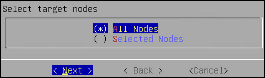
Select the target node and select Next.
The Summary screen confirming the file to be deployed appears.
Select Next.
The files are deployed to the target nodes.
6.2.4 - Managing a site
In case of multiple sites, a site can be managed using the following process.
Using Site Management, you can perform the following operations:
- Obtain Site Information
- Add a site
- Remove sites added to the cluster, if more than one site exists in the cluster
- Rename a site
- Set the master site
The following screen shows the Site Management screen.

View a Site
You can view the information for all the sites in the cluster by selecting Show sites information. When a cluster is created, a master site with site1 is created by default. The following screen displays the Site Information screen.

Adding Sites to a Cluster
This section describes the steps to add multiple sites to a cluster from the CLI Manager.
To add a site to a cluster:
On the CLI Manager, navigate to Tools > Trusted Appliances Cluster > Site Management > Add Site.
The following screen appears.

Select OK.
The new site is added.
Renaming a Site
This section describes the steps to rename a site from the CLI Manager.
To rename a site:
On the CLI Manager, navigate to Tools > Trusted Appliances Cluster > Site Management > Update Cluster Site Settings.
Select the required site and select Rename.
The Rename Site screen appears.
Type the required site name and select OK.
The site is renamed.
Setting a Master Site from the CLI Manager
This section describes the steps to set a master site from the CLI Manager.
To set a master site from the CLI Manager:
On the CLI Manager, navigate to Tools > Trusted Appliances Cluster > Site Management > Set Master Site.
The Set Master Site screen appears.
Select the required site and select Set Master.
A message Operation has been completed successfully appears and the new master site is set. An empty cluster site does not contain any node. You cannot set an empty cluster site as a master site.
Deleting a Cluster Site
This section describes the steps to delete a cluster site from the CLI Manager. You can only delete an empty cluster site.
To delete a cluster site:
In the CLI Manager of the node hosting the appliance cluster, navigate to Tools > Trusted Appliances Cluster > Site Management > Remove: Remove Cluster sites(s).
The Remove Site screen appears.
Select the required site and select Remove.
Select OK.
The site is deleted.
6.2.5 - Node Management
Details about Node Management.
Using Node Management, you can:
- List the nodes - The same option as List Nodes menu, refer here.
- Add a node to the cluster - If your appliance is a part of the cluster, and you want to add a remote node to this cluster.
- Update cluster information - For updating the identification entries.
- Manage communication method of the nodes.
- Remove a remote node from the cluster.
6.2.5.1 - Show Cluster Nodes and Status
View the status of all the nodes in the cluster.
The following table describes the fields that appear on the status screen.
| Field | Description |
|---|---|
| Hostname | Hostname of the node |
| Address | IP address of the node |
| Label | Label assigned to the node |
| Type | Build version of the node |
| Status | Online/Blocked/Offline |
| Node Messages | Messages that appear for the node |
| Connection | Connection setting of the node (On/Off) |
6.2.5.2 - Viewing the Cluster Status using the CLI Manager
View the status of all the nodes in a cluster.
To view the status of the nodes in a cluster using the CLI Manager:
In the CLI Manager, navigate to Tools > Trusted Appliances Cluster > Node Management > List Nodes.
The screen displaying the status of the nodes appears.

Select Change View to change the view.
The list of different reports is as follows:
- List View: Displays the list of all the nodes.
- Labels View: Displays a grouped view of the nodes.
- Status View: Displays the status of the nodes.
- Report view: Displays the cluster diagnostics, network or connectivity issues, and generate error or warning messages if required.
6.2.5.3 - Adding a Remote Node to a Cluster
The steps to add a remote node to a cluster.
To add a remote node to the cluster:
In the CLI Manager of the node hosting the cluster, navigate to Tools > Trusted Appliances Cluster > Node Management > Add Node: Add a remote node to this cluster.
The Add Node screen appears.

Enter the credentials of the local node user, which must have administrative privileges, into the Username and Password text boxes.
Type the preferred communication method on the Preferred Method text box.
Type the accessible communication method of the target node in the Reachable Address text box.
Type the credentials of the target node user in the Username and Password text boxes.
Select OK.
The node is invited to the cluster.
6.2.5.4 - Updating Cluster Information using the CLI Manager
The steps to update Cluster Information.
It is recommended not to change the name of the node after you create the cluster task.
To update cluster information:
In the CLI Manager of the node hosting the cluster, navigate to Tools > Trusted Appliances Cluster > Node Management > Update Cluster Information.
The Update Cluster Information screen appears.

Type the name of the node in the Name text box.
Type the information describing the node in the Description text box.
Type the required label for the node in the Labels text box.
Select OK.
The details of the node are updated.
6.2.5.5 - Managing Communication Methods for Local Node
The steps to add, edit and delete a communication method.
Every node in a network is identified using a unique identifier. A communication method is a qualifier for the remote nodes in the network to communicate with the local node.
There are two standard methods by which a node is identified:
- Local IP Address of the system (ethMNG)
- Host name
The nodes joining a cluster use the communication method to communicate with each other. The communication between nodes in a cluster occur over one of the accessible communication methods.
Adding a Communication Method from the CLI Manager
This section describes the steps to add a communication method from the CLI Manager.
To add a communication method from the CLI Manager:
In the ESA CLI Manager, navigate to Tools > Clustering > Trusted Appliances Cluster.
In the Cluster Services screen, select Node Management: Add/Remove Cluster Nodes/ Information.
In the Node Management screen, select Manage node’s local communication methods.
In the Select Communication Method screen, select Add.
Type the required communication method and select OK.
The new communication method is added.
Ensure that the length of the text is less than or equal to 64 characters.
Editing a Communication Method from the CLI Manager
This section describes the steps to edit a communication method from the CLI Manager.
To add a communication method from the CLI Manager:
In the ESA CLI Manager, navigate to Tools > Clustering > Trusted Appliances Cluster.
In the Cluster Services screen, select Node Management: Add/Remove Cluster Nodes/ Information.
In the Node Management screen, select Manage node’s local communication methods.
In the Select Communication Method screen, select the communication method to edit and select Edit.
In the Edit method screen, enter the required changes and select OK.
The changes to the communication method are complete.
Deleting a Communication Method from the CLI Manager
This section describes the steps to delete a communication method from the CLI Manager.
To delete a communication method from the CLI Manager:
In the ESA CLI Manager, navigate to Tools > Clustering > Trusted Appliances Cluster.
In the Cluster Services screen, select Node Management: Add/Remove Cluster Nodes/ Information.
In the Node Management screen, select Manage node’s local communication methods.
In the Select Communication Method screen, select the required communication method and select Delete.
The communication method of the node is deleted.
6.2.5.6 - Managing Local to Remote Node Communication
You can select the method that a node uses to communicate with another node in a network. The communication methods of all the nodes are visible across the cluster. You can select the specific communication mode to connect with a specific node in the cluster. In the Node Management screen, you can set the communication between a local node and remote node in a cluster.
You can also set the preferred method that a node uses to communicate with other nodes in a network. If the selected communication method is not accessible, then the other available communication methods of the target node are used for communication.
Selecting a Local to Remote Node Communication Method
This section describes the steps to select a local to remote node communication method.
To select a local to remote node communication method:
In the ESA CLI Manager, navigate to Tools > Clustering > Trusted Appliances Cluster.
In the Cluster Services screen, select Node Management: Add/Remove Cluster Nodes/ Information.
In the Node Management screen, select Manage local to other nodes communication methods.
In the Manage local to other nodes communication method, select the required node for which you want to change the communication method.
Select Change.
Select the required communication method and select Choose. If a new communication must be added so it can be chosen as the required communication method, select Add New to add it.
Select Ok.
The communication method is selected to communicate with the remote node in the cluster.
Changing a Local to Remote Node Communication Method
This section describes the steps to change a local to remote node communication method.
To change a local to remote node communication method:
In the ESA CLI Manager, navigate to Tools > Clustering > Trusted Appliances Cluster.
In the Cluster Services screen, select Node Management: Add/Remove Cluster Nodes/ Information.
In the Node Management screen, select Manage local to other nodes communication methods.
In the Manage local to other nodes communication method screen, select a remote node and select Change.
The following screen appears.
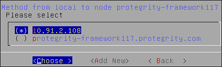
Select the required communication method.
Select Choose.
The new local to other nodes communication methods is set.
6.2.5.7 - Removing a Node from a Cluster using CLI Manager
The steps to remove a remote node from a cluster.
Before attempting to remove a node, verify if it is associated with a cluster task. If a node is associated with a cluster task that is based on the hostname or IP address, then the Remove a (remote) cluster node operation will not remove node from the cluster. Ensure that you delete all such tasks before removing any node from the cluster.
To remove a node from a cluster using the CLI Manager:
In the ESA CLI Manager, navigate to Tools > Trusted Appliances Cluster.
In the Cluster Services screen, select Node Management: Add/Remove Cluster Nodes/Information.
The following screen appears.

Select Remove: Delete a (remote) cluster node and select OK.
The screen displaying the nodes in the cluster appears.
Select the required node and select OK.
The following screen appears.

Select OK.
Select REFRESH to view the updated status.
6.2.5.8 - Uninstalling Cluster Services
The steps to uninstall the cluster services on a node.
Before attempting to remove a node, verify if it is associated with a cluster task. If a node is associated with a cluster task that is based on the hostname or IP address, then the Uninstall Cluster Services operation will not uninstall the cluster services on the node. Ensure that you delete all such tasks before uninstalling the cluster services.
To remove a node from a cluster using the CLI Manager:
In the ESA CLI Manager, navigate to Tools > Trusted Appliances Cluster.
In the Cluster Services screen, select 7 Uninstall : Uninstall Cluster Services.
A confirmation message appears.
Select Yes.
The cluster services are uninstalled.
6.2.6 - Trusted Appliances Cluster
A Trusted Appliances cluster can be used to transfer data from one node to other nodes regardless of their location, as long as standard SSH access is supported. This mechanism allows you to run remote commands on remote cluster nodes, transfer files to remote nodes and export configurations to remote nodes. Trusted appliances clusters are typically used for disaster recovery. The trusted appliance cluster can be configured and controlled using the Appliance Web UI as well as the Appliance CLI.
Clustering details are fully explained in section Trusted Appliances Cluster (TAC). In that section you will find information how to:
- Setup a trusted appliances cluster
- Add the appliance to an existing trusted appliances cluster
- Remove an appliance from the trusted appliances cluster
- Manage cluster nodes
- Run commands on cluster nodes
Using the cluster maintenance, you can perform the following functions:
- List cluster nodes
- Update cluster keys
- Redeploy local cluster configuration to all nodes
- Review cluster service interval
- Execute commands as OS root user
6.2.6.1 - Updating Cluster Key
The steps to generate a new set of the cluster SSH keys.
Before you begin
Ensure that all the nodes in the cluster are active, before changing the cluster key.
If a new key is deployed to a node that is unreachable, then connect the node to the cluster. In this scenario, remove the node from the cluster and re-join the cluster.
Generate a new set of the cluster SSH keys to the nodes that are directly connected to the local node. This ensures that the trusted appliance cluster is secure.
To re-generate cluster keys:
In the ESA CLI Manager, navigate to Tools > Clustering > Trusted Appliances Cluster > Maintenance: Update Cluster Settings.
The following screen appears.
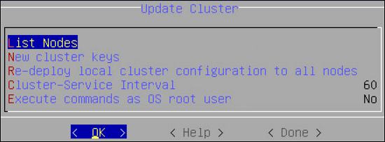
Select New Cluster Keys.
A message to re-generate the cluster keys appears.
Select Yes.
The new keys are deployed to the nodes that are directly connected.
6.2.6.2 - Redeploy Local Cluster Configuration to All Nodes
You can redeploy the local cluster configuration to force it to be applied on all connected nodes. Usually there is no need for such operation since the configurations are synchronized automatically. However, if the cluster status service is stopped or you want to force a specific configuration, then you can use this option to force the configuration.
When you select to Redeploy local cluster configuration to all nodes in the Update Cluster dialog box, the operation is performed at once with no confirmation.
6.2.6.3 - Cluster Service Interval
The cluster provides an auto-update mechanism that runs in the background as a background service which is responsible for updating local and remote cluster configurations and cluster health checks.
You can specify the cluster service interval in the Cluster Service Interval dialog box.

The interval (in seconds) specifies the sleep time between cluster background updates/operations. For example, if the specified value is 120 seconds, then every two minutes the cluster service will update its status and synchronize its cluster configuration with the other nodes (if changes identified).
6.2.6.4 - Execute Commands as OS Root User
By default, the cluster user is a restricted user which means that the cluster commands will be restricted by the OS. There are scenarios where you would like to disable these restrictions and allow the cluster user to run as the OS root user.
Using the details in the table below, you can specify whether to execute the commands as root or as a restricted user.
| You can specify… | To… |
|---|---|
| Yes | Always execute commands as the OS root user. It is less secure, risky if executing the wrong command. |
| No | Always execute commands as non-root restricted user. It is more secure, but not common for many scenarios. |
| Ask | Always be asked before a command is executed. |
6.3 - Working with Xen Paravirtualization Tool
Using Tools > Clustering Tool, you can setup an appliance virtual environment. The default installation of a Protegrity appliance uses hardware virtualization mode (HVM). The appliance can be reconfigured to use parallel virtualization mode (PVM) to optimize the performance of virtual guest machines.
Protegrity supports these virtual servers:
- Xen®
- Microsoft Hyper-V™
- KVM Hypervisor
XEN paravirtualization details are fully covered in section Xen Paravirtualization Setup. In that section you will find information how to:
- Set up Xen paravirtualization
- Follow the paravirtualization process
6.4 - Working with the File Integrity Monitor Tool
Using Tools > File Integrity Monitor, you can make a weekly check. The content modifications can be viewed by the Security Officer since the PCI specifications require that sensitive files and folders in the Appliance are monitored. This information contains password, certificate, and configuration files. All changes made to these files can be reviewed by authorized users.
6.5 - Rotating Appliance OS Keys
The steps to rotate appliance OS keys.
When you install the appliance, it generates multiple security identifiers such as, keys, certificates, secrets, passwords, and so on. These identifiers ensure that sensitive data is unique between two appliances in a network. When you receive a Protegrity appliance image or replicate an appliance image on-premise, the identifiers are generated with certain values. If you use the security identifiers without changing their values, then security is compromised and the system might be vulnerable to attacks. Using the Rotate Appliance OS Keys, you can randomize the values of these security identifiers on an appliance. This tool must be run only when you finalize the ESA from a cloud instance.
Set ESA communication and key rotations
When an appliance, such as DSG, communicates with ESA, the Set ESA communication must be performed. Before running the Set ESA communication process, ensure appliance OS keys are rotated.
For example, if the OS keys are not rotated, then you might not be able to add the appliances to a Trusted Appliances Cluster (TAC).
To rotate appliance OS keys:
From the CLI Manager, navigate to to Tools > Rotate Appliance OS Keys.
Enter the root credentials.
The following screen appears.
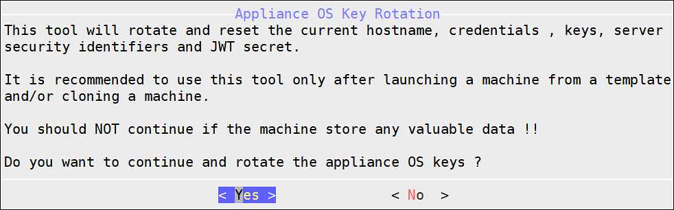
Select Yes.
The following screen appears.
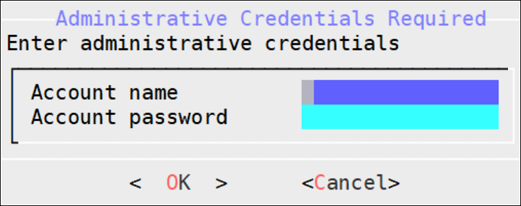
If you select No, then the Rotate Appliance OS Keys operation is discarded.
Enter the administrative credentials and select OK.
The following screen appears.
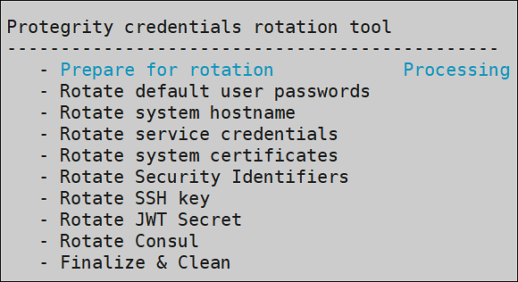
The following screen appears.
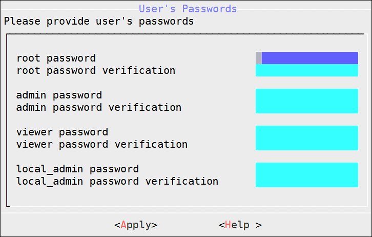
To update the user passwords, provide the credentials for the following users.
- root
- admin
- viewer
- local_admin
If you have deleted any of the default users, such as admin or viewer, those users will not be listed in the User’s Passwords screen.
Select Apply.
The user passwords are updated and the appliance OS keys are rotated.
After rotating appliance keys the hostname of ESA changes, update the hostname in the configuration files and rotate the Insight certificates using the steps from Updating the host name or domain name of the ESA.
6.6 - Managing Removable Drives
The steps to enable or disable the access to the removable disks.
As a security feature, you can restrict access to the removable drives attached to your appliances. You can enable or disable the access to the removable disks, such as, CD/DVD drive or USB Flash drives.
The access to the removable disks is enabled by default.
Disabling CD or DVD drive
To disable CD or DVD drive:
On the CLI Manager, navigate to Tools > Removable Media Management > Disable CD/DVD Drives.
Press ENTER.
The following message appears.
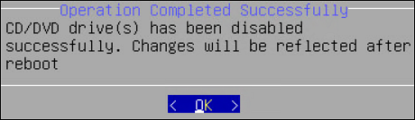
Disabling USB Flash Drive
To disable USB flash drive:
On the CLI Manager, navigate to Tools > Removable Media Management > Disable USB Flash Drives..
Press ENTER.
The following message appears.
Enabling CD or DVD Drive
To enable CD/DVD drive:
On the CLI Manager, navigate to Tools > Removable Media Management > Enable CD/DVD Drives.
Press ENTER.
Enabling USB Flash Drive
To enable USB flash drive:
On the CLI Manager, navigate to Tools > Removable Media Management > Enable Flash Drives.
Press ENTER.
6.7 - Tuning the Web Services
Monitor and configure the Application Protector Web Service Sessions.
Using Tools > Web Services Tuning, you can monitor and configure the Application Protector Web Service Sessions. You can view information such as Session Shared Memory ID, maximum open sessions, open sessions, free sessions, and session timeout.
CAUTION: It is recommended to contact Protegrity Support before applying any changes for Web Services.
In the Web Services Tuning screen you can find and configure the following fields.
Start Servers: In the StartServers field, you configure the number of child servers processes created on startup. Since the number of processes is dynamically controlled depending on the load, there is usually no reason to adjust the default parameter.
Minimum Spare Servers: In the MinSpareServers field, you set the minimum number of child server processes not handling a request. If the number of such processes is less than configured in the MinSpareServers field, then the parent process creates new children at a maximum rate of 1 per second. It is recommended to change the default value only when dealing with very busy sites.
Maximum Spare Servers: In the MaxSpareServers field, you set the maximum number of child server processes not handling a request. When the number of such processes exceeds the number configured in MaxSpareServers, the parent process kills the excessive processes.
It is recommended to change the default value only when dealing with very busy sites. If you try to set the value lower than MinSpareServers, then it will automatically be adjusted to MinSpareServers value +1.
Maximum Clients: In the MaxClients field, you set the maximum number of connections to be processed simultaneously.
Maximum Requests per Child: In the MaxRequestsPerChild field, you set the limit on the number of requests that an individual child server will handle during its life. When the number of requests exceeds the value configured in the MaxRequestsPerChild field, the child process dies. If you set the MaxRequestsPerChild value to 0, then the process will never expire.
Maximum Keep Alive Requests: In the MaxKeepAliveRequest field, you can set the maximum number of requests that can be allowed during a persistent connection. If you set 0, then the number of allowed request will be unlimited. For maximum performance, leave this number high.
Keep Alive Timeout: In the KeepAliveTimeout field, you can set the number of seconds to wait for the next request from same client on the same connection.
6.8 - Tuning the Service Dispatcher
Configuring the parameters to improve service dispatcher performance.
The Service Dispatcher parameters are the Apache Multi-Processing Module (MPM) worker parameters. The Apache MPM Worker module implements a multi-threaded multi-process web server that allows it to serve higher number of requests with limited system resources. For more information about the Apache MPM Worker parameters, refer to https://httpd.apache.org/docs/2.2/mod/worker.html.

To improve service dispatcher performance, navigate to Tools > Service Dispatcher Tuning.
The following table provides information about the configurable parameters and recommendations for Service Dispatcher performance.
| Parameter | Default Value | Description |
|---|---|---|
| StartServers | 64 | The number of apache server instances that start at the beginning when you start Apache. It is recommended not to enter the StartServers value more than the value for MaxSpareThreads, as this results in processes being terminated immediately after initializing. |
| ServerLimit | 1600 | The maximum number of child processes. It is recommended to change the ServerLimit value only if the values in MaxClients and ThreadsPerChild need to be changed. |
| MinSpareThreads | 512 | The minimum number of idle threads that are available to handle requests. It is recommended to keep the MinSpareThreads value higher than the estimated requests that will come in one second. |
| MaxSpareThreads | 1600 | The maximum number of idle threads. It is recommended to reserve adequate resources to handle MaxClients. If MaxSpareThreads are insufficient, the webserver will terminate and frequently create child processes, reducing performance. |
| ThreadLimit | 512 | The upper limit of the configurable threads per child process. To avoid unused shared memory allocation, it is recommended not to set the ThreadLimit value much higher than the ThreadsPerChild value. |
| ThreadsPerChild | 288 | The number of threads created by each child process. It is recommended to keep the ThreadsPerChild value such that it can handle common load on the server. |
| MaxRequestWorkers | 40000 | The maximum number of requests that can be processed simultaneously. It is recommended to take into consideration the expected load when setting the MaxRequestWorkers values. Any connection that comes over the load, will drop, and the details can be seen in the error log. Error log file path - /var/log/apache2-service_dispatcher/errors.log |
| MaxConnectionsPerChild | 0 | The maximum number of connections that a child server process can handle in its life. If the MaxConnectionsPerChild value is reached, this process expires. It is recommended to set the MaxConnectionsPerChild value to 0, so that this process never expires. |
6.9 - Working with Antivirus
The AntiVirus program uses ClamAV, an open source and cross-platform antivirus engine designed to detect malicious trojan, virus, and malware threats. A single file or directory, or the whole system can be scanned. Infected file or files are logged and can be deleted or moved to a different location, as required.
The Antivirus option allows you to perform the following actions.
| Option | Description |
|---|---|
| Scan Result | Displays the list of the infected files in the system. |
| Scan now | Allows the scan to start. |
| Options | Allows access to customize the antivirus scan options. |
| View log | Displays the list of scan logs. |
Customizing Antivirus Scan Options from the CLI
To customize Antivirus scan options from the CLI:
Go to Tools > AntiVirus.
Select Options.
Press ENTER.
The following table provides a list of the choices available to you to customize scan options.
Table 1. List of all scan options
Option Selection Description Action Ignore Ignore the infected file and proceed with the scan. Move to directory Move the infected files to specific directory. In the text box, enter the path where the infected file should be moved.Delete infected file Remove the infected file from the directory. Recursive True Scan sub-directories. False Do not scan sub-directories. Scan directory Path of the directory to be scanned.
7 - Working with Preferences
Set up console preferences.
You can set up your console preferences using the Preferences menu.

You can choose to configure the following preferences:
- Show system monitor on OS Console
- Require password for CLI system tools
- Show user Notifications on CLI load
- Minimize the timing differences
- Set uniform response time for failed login
- Enable root credentials check limit
- Enable AppArmor
- Enable FIPS Mode
- Basic Authentication for REST APIs
7.1 - Viewing System Monitor on OS Console
You can choose to show a performance monitor before switching to OS Console. If you choose to show the monitor, then the dialog delays for one second before the initialization of the OS Console. The value must be set to Yes or No.
7.2 - Setting Password Requirements for CLI System Tools
Many CLI tools and utilities require different credentials, such as root and admin user credentials. You can choose to require or not to require a password for CLI system tools. The value must be set to Yes or No.
Specifying No here will allow you to execute these tools without having to enter the system passwords. This can be useful when the system administrator is the security manager as well. This setting is not recommended since it is makes the Appliance less secure.
7.3 - Viewing user notifications on CLI load
You can choose to display notifications in the CLI home screen every time a user logs in to the ESA. These notifications are specific to the user. The value must be set to Yes or No.
7.4 - Minimizing the Timing Differences
You sign in to the appliance to access different features provided. When you sign in with incorrect credentials, the request is denied and the server sends an appropriate response indicating the reason for failure to log in. The time taken to send the response varies based on the different authentication failures, such as invalid password, invalid username, expired username, and so on. This time interval is vulnerable to security attacks for obtaining valid users from the system. Thus, to mitigate such attacks, you can minimize the time interval to reduce the response time between an incorrect sign-in and server response. To enable this setting, toggle the value of the Minimize the timing differences option from the CLI Manager to Yes.
The default value of the Minimize the timing differences option is No.
When you login with a locked user account, a notification indicating that the user account is locked appears. This notification will not appear when the value of Minimize the timing differences option is Yes. Instead you will get a notification indicating that the username or password is incorrect.
7.5 - Setting a Uniform Response Time
If you login to the ESA Web UI with invalid credentials, then the time taken to respond to various authentication scenario failures, varies. The various scenarios can be invalid username, invalid password, expired username, and so on. This variable time interval may introduce a timing attack on the system.
To reduce the risk of a timing attack, you need to reduce the variable time interval and specify a response time to handle invalid credentials. Thus, the response time for the authentication scenarios remains the same.
The response time for the authentication scenarios are based on different factors such as, hardware configurations, network configurations, and system performance. Thus, the standard response time would differ between organizations. It is therefore recommended to set the response time based on the settings in your organization.
For example, if the response time for a valid login scenario is 5 seconds, then you can set the uniform response time as 5.
Enter the time interval in seconds and select OK to enable the feature. Alternatively, enter 0 in the text box to disable the feature.
7.6 - Limiting Incorrect root Login
If you log in to a system with an incorrect password, the permission to access the system is denied. Multiple attempts to log in with an incorrect password open a route to brute force attacks on the system. Brute force is an exhaustive hacking method, where a hacker guesses a user password over successive incorrect attempts. Using this method, a hacker gains access to a system for malicious purposes.
In our appliances, the root user has access to various operations in the system such as accessing OS console, uploading files, patch installation, changing network settings, and so on. A brute force attack on this user might render the system vulnerable to other security attacks. Therefore, to secure the root login, you can limit the number of incorrect password attempts to the appliance. On the Preferences screen, enable the Enable root credentials limit check option to limit an LDAP user from entering incorrect passwords for the root login. The default value of the Enable root credentials limit check option is Yes.
If you enable the Enable root credentials limit check, the LDAP user can login as root only with a fixed number of successive incorrect attempts. After the limit on the number of incorrect attempts is reached, the LDAP user is blocked from logging in as root, thus preventing a brute force attack. After the locking period is completed, the LDAP user can login as root with the correct password.
When you enter an incorrect password for the root login, the events are recorded in the logs.
By default, the root login is blocked for a period of five minutes after three incorrect attempts. You can configure the number of incorrect attempts and the lock period for the root login.
For more information about configuring the lock period and successive incorrect attempts, contact Protegrity Support.
7.7 - Enabling Mandatory Access Control
For implementing Mandatory Access Control, the AppArmor module is introduced on Protegrity appliances. You can define profiles for protecting files that are present in the appliance.
7.8 - FIPS Mode
The steps to enable or disable the FIPS mode.
The Federal Information Processing Standards (FIPS) defines guidelines for data processing. These guidelines outline the usage of the encryption algorithms and other data security measures before accessing the data. Only a user with administrative privileges can access this functionality.
For more information about the FIPS, refer to https://www.nist.gov/standardsgov/compliance-faqs-federal-information-processing-standards-fips.
Enabling the FIPS Mode
To enable the FIPS mode:
Login to the ESA CLI Manager and navigate to Preferences.
Enter the root password and click OK.
The Preferences screen appears.

Select the Enable FIPS Mode.
Press Select.
The Enable FIPS Mode dialog box appears.

Select Yes and click OK.
The following screen appears.

For more information on the anti-virus settings, refer here.
Click OK.
The following screen appears. Click OK.

After the FIPS mode is enabled, restart the ESA to apply the changes.
Disabling the FIPS Mode
To disable the FIPS mode:
Login to the ESA CLI Manager and navigate to Preferences.
Enter the root password and click OK.
The Preferences screen appears.

Select the Enable FIPS Mode.
Press Select.
The Enable FIPS Mode dialog box appears.

Select No and click OK.
The following screen appears. Click OK.

After the FIPS mode is disabled, restart the ESA to apply the changes.
7.9 - Basic Authentication for REST APIs
The steps to enable or disable the basic authentication.
The Basic Authentication mechanism provides only the user credentials to access protected resources on the server. The user credentials are provided in an authorization header to the server. If the credentials are accurate, then the server provides the required response to access the APIs.
For more information about the Basic Authentication, refer here.
Disabling the Basic Authentication
To disable the Basic Authentication:
Login to the ESA CLI Manager and navigate to Preferences.
Enter the root password and click OK.
The Preferences screen appears.

Select the Basic Authentication for Rest APIs.
Press Select.
The Basic Authentication for REST APIs dialog box appears.

Select No and click OK.
The message Basic Authentication for REST APIs disabled successfully appears.
Click OK.
Important:
If the Basic Authentication is disabled, then the following APIs are affected:
- GetCertificate REST API: Fetch certificate to protector.
- DevOps API: Policy Management REST API.
- RPS REST API: Resilient Package Immutable REST API.The getcertificate stops working for the 9.1.x protectors when the Basic Authentication is disabled.However, the DevOps and RPS REST APIs can also use the Certificate and JWT Authentication support.
Enabling the Basic Authentication
To enable the Basic Authentication:
Login to the ESA CLI Manager and navigate to Preferences.
Enter the root password and click OK.
The Preferences screen appears.

Select the Basic Authentication for REST APIs.
Press Select.
The Basic Authentication for REST APIs dialog box appears.

Select Yes and click OK.
The message Basic Authentication for REST APIs enabled successfully appears.
Click OK.
8 - Command Line Options
Run the commands to configure the ESA.
8.1 - Forwarding system logs to Insight
When the logging components are configured on the ESA or the appliance, system logs are sent to Insight. Insight stores the logs in the Audit Store. Configure the system to send the system logs to Insight.
Log in to the CLI Manager on the ESA or the appliance.
Navigate to Tools > PLUG - Forward logs to Audit Store.

Enter the password for the root user and select OK.

Enter the IP address of all the nodes in the Audit Store cluster with the Ingest role and select OK. Specify multiple IP addresses separated by comma.
To identify the node with the Ingest roles, log in to the ESA Web UI and navigate to Audit Store > Cluster Management > Overview > Nodes.

Enter y to fetch certificates and select OK.
Specifying y fetches td-agent certificates from target node. These certificates can then be used to validate and connect to the target node. They are required to authenticate with Insight while forwarding logs to the target node. The passphrase for the certificates are stored in the /etc/ksa/certs directory.
Specify n if the certificates are already available on the system, fetching certificates are not required, or custom certificates are to be used.

Enter the credentials for the admin user of the destination machine and select OK.

The td-agent service is configured to send logs to Insight and the CLI menu appears.
8.2 - Forwarding audit logs to Insight
The audit logs are the data security operation-related logs, such as protect, unprotect, and reprotect and the PEP server logs. The audit logs from the appliance, such as, the DSG are forwarded through the Log Forwarder service to Insight. Insight stores the logs in the Audit Store on the ESA.
The example provided here is for DSG. Refer to the specific protector documentation for the protector configuration.
Log in to the CLI Manager on the appliance.
Navigate to Tools > ESA Communication.

Enter the password of the root user of the appliance and select OK.

Select the Logforwarder configuration option, press Tab to select Set Location Now, and press Enter.
The ESA Location screen appears.

Select the ESA to connect with, then press Tab to select OK, and press ENTER.
The ESA selection screen appears.

To enter the ESA details manually, select the Enter manually option. A prompt is displayed to enter the ESA IP address or hostname.
Enter the ESA administrator username and password to establish communication between the ESA and the appliance. Press Tab to select OK and press Enter.
The Enterprise Security Administrator - Admin Credentials screen appears.

Enter the IP address or hostname for the ESA. Press Tab to select OK and press ENTER. Specify multiple IP addresses separated by comma. To add an ESA to the list, specify the IP addresses of all the existing ESAs in the comma separated list, and then specify the IP for the additional ESA.
The Forward Logs to Audit Screen screen appears.

After successfully establishing the connection with the ESA, the following summary dialog box appears. Press Tab to select OK and press Enter.

Repeat step 1 to step 8 on all the appliance nodes in the cluster.
8.3 - Applying Audit Store Security Configuration
The Apply Audit Store Security Configs setting is available for configuring the Audit Store security. This setting must be used after upgrading from an earlier version of the ESA when custom certificates are used. Run the following steps after the upgrade is complete and custom certificates are applied for td-agent, Audit Store, and Analytics, if installed.
From the ESA Web UI, navigate to System > Services > Audit Store.
Start the Audit Store Repository service.
Open the ESA CLI.
Navigate to Tools.
Run Apply Audit Store Security Configs.

8.4 - Setting the total memory for the Audit Store Repository
The Set Audit Store Repository Total Memory tool is used to specify the total RAM allocated for the Audit Store Repository on the ESA.
The RAM allocated for the Audit Store on the appliance is set to a optimal default value. If this value is not as per the existing requirement, then use this tool to modify the RAM allocation. However, when certain operations are performed, such as, when the role for the node is modified or a node is removed from the cluster, then the value set is overwritten. Additionally, the RAM allocation reverts to the optimal default value. In this case, perform these steps again for setting the RAM allocation after modifying the role of the node or adding a node back to the Audit Store cluster.
From the ESA Web UI, navigate to System > Services > Audit Store.
Start the Audit Store Repository service.
Open the ESA CLI.
Navigate to Tools.
Run Set Audit Store Repository Total Memory.

Enter the password for the root user and select OK.

Specify the total memory that must be allocated for the Audit Store Repository and select OK.

Select Exit to return to the menu.

Repeat the steps on the remaining nodes, if required.
8.5 - Rotating Insight certificates
Rotate the Insight certificates after the the ESA certificates are rotated. This refreshes the Insight-related certificates that is required for the Audit Store nodes to communicate with the other nodes in the Audit Store cluster and the ESA.

For more information about rotating the Insight certificates, refer here.