Policy Management
Overview of the policy management functionality provided by Protegrity Data Security Platform.
The value of any company or its business is in its data. The company or business suffers serious issues if an unauthorized user gets access to the data. Therefore, it becomes necessary for any company or business to protect its data.
The data may contain sensitive information like personally identifiable information, company secrets such as pricing information or intellectual property etc. The process of protecting sensitive data to protect the privacy and personal identity of individuals is called De-Identification.
When de-identifying data, the analysis consists of:
- Anonymization – In anonymization, the intent is to protect privacy by sanitizing any information that could lead to the individual being identified. The de-identified data cannot be re-identified. It includes methods like encryption, masking etc.
- Pseudonymization – In pseudonymization, artificial identifiers or pseudonyms replace the identifying data within a data record. The de-identified data can be re-identified only to authorized users. It includes methods like vaultless tokenization.
The Protegrity methodology together with policy management provides a framework for designing and delivering enterprise data security solutions. Data security solutions, when adopted within an organization, ensures the security of information assets. One of the key components of data security is a policy.
Policy is a set of rules that defines how sensitive data needs to be protected. These policies are designed or created and then distributed to locations in the enterprise, where data needs to be protected.
Policy management is a set of capabilities for creating, maintaining, and distributing the policies.
1 - Protegrity Data Security Methodology
A general overview of the methodology used in the Protegrity Data Security Management.
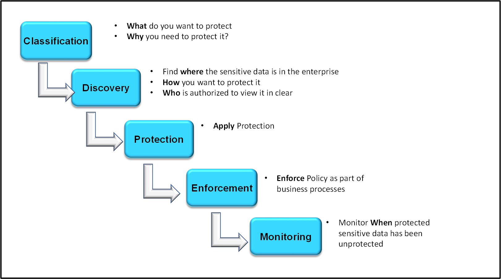
The data security policy each organization creates within ESA is based on requirements with relevant regulations. A policy helps you to determine, specify and enforce certain data security rules. These data security rules are as shown in the following figure.
Classification
This section discusses about the classification of Policy Management in ESA.
What do you want to protect?
The data that is to be protected needs to be classified. This step determines the type of data that the organization considers sensitive. The compliance or security team will choose to meet certain standard compliance requirements with specific law or regulation. For example, the Payment Card Industry Data Security Standard (PCI DSS) or the Health Information Portability and Accessibility Act (HIPAA).
In ESA, you classify the sensitive data fields by creating ‘Data Elements’ for each field or type of data.
Why do you need to protect?
The fundamental goal of all IT security measures is the protection of sensitive data. The improper disclosure of sensitive data can cause serious harm to the reputation and business of the organization. Hence, the protection of sensitive data by avoiding identity theft and protecting privacy is for everyone’s advantage.
Discovery
This section discusses about the discovery of Policy Management in ESA.
Where is the data located in the enterprise?
The data protection systems are the locations in the enterprise to focus on as the data security solution is designed. Any data security solution identifies the systems that contains the sensitive data.
In ESA, you specify locations by creating a Data Store.
How you want to protect it?
Data protection has different scenarios which require different forms of protection. For example, tokenization is preferred over encryption for credit card protection. The technology used must be understood to identify a protection method. For example, if a database is involved, Protegrity identifies a Protector to match up with the technology used to achieve protection of sensitive data.
Who is authorized to view it in the clear?
In any organization, the access to unprotected sensitive data must be given only to the authorized stakeholders to accomplish their jobs. A policy defines the authorization criteria for each user. The users are defined in the form of members of roles. A level of authorization is associated with each role which assigns data access privileges to all members in the role.
Protection
This section discusses about protection of Policy Management in ESA.
The Protegrity Data Security Platform delivers the protection through a set of Data Protectors. The Protegrity Protectors meet the governance requirements to protect sensitive data in any kind of environment. ESA delivers the centrally managed data security policies as part of a package and the Protectors locally enforce them. It also collects audit logs of all activity in their systems and sends back to ESA for reporting.
Enforcement
This section discusses about enforcement of Policy Management in ESA.
The policy is created to enforce the data protection rules that fulfils the requirements of the security team. It is deployed to all Protegrity Protectors that are protecting sensitive data at protection points.
Monitoring
This section discusses about monitoring audits related to Policy Management in ESA.
As a policy is enforced, the Protegrity Protectors collects audit logs in their systems and reports back to Insight. Audit logs helps you to capture authorized and unauthorized attempts to access sensitive data at all protection points. It also captures logs on all changes made to policies.
2 - Package Deployment in Protectors
A general overview of how packages are deployed to Protectors.
This section describes Package Deployment in protectors.
Protegrity enables you to deploy packages to protectors. A package can be a single policy, a standalone entity such as a CoP ruleset, or a combination of a policy and other entities. For example, a package can include the following entities:
Data Security Policy - Security policies used to protect, unprotect, and reprotect data.
CoP Ruleset - Instructions used by the Protegrity Data Security Gateway (DSG) to transform data.
For more information about the CoP Ruleset, refer to Ruleset reference.
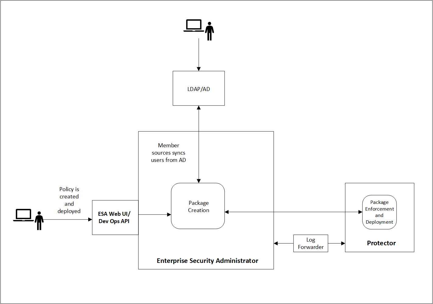
The following image illustrates how the Data Security Policy that is defined in the ESA reaches the protectors as part of a package. A Data Security Policy is created and deployed in the ESA either using the ESA Web UI or the DevOps API. When the protector sends a request to the ESA, the ESA creates a package containing the policy. The protector then pulls the package and the related metadata. If a change is made to any of the policies that are part of the package, the protector pulls the updated package from the ESA. There can be multiple scenarios when any change in policy is made.
Important: The deployment scenario explained in this section applies to 10.0.0 protectors and later.
3 - Initializing the Policy Management
Instruction on how to initialize the Policy Management.
When you install and log in to the ESA Web UI for the first time, you must initialize the Policy Management (PIM). This initialization creates the keys-related data and the policy repository. This section describes the steps to initialize the Policy Management (PIM) to load the Policy Management-specific information on the ESA Web UI. When you try to access any of the Policy Management or Key Management screens on the ESA Web UI, a request to initialize the PIM appears.
Prior to the installation of protectors, ensure that you perform the following steps to initialize the Policy Management.
To initialize the Policy Management:
On the ESA Web UI, click Policy Management or Key Management.
Click any option available in the Policy Management or Key Management area.
The following screen to initialize PIM appears.

Click Initialize PIM.
A confirmation message box appears.
Click Ok.
The policy management information appears in the Policy Management area.
You can also initialize the PIM using the Policy Management REST API.
4 - Components of a Policy
An overview of the components of a policy.
A policy contains multiple components that work together to enforce protection at the protection endpoints. The role component and policy is tied closely. Any changes made to the organization LDAP, such as a user linked to a role is added or deleted, result in an update to the policy. The automatic deployment of policy is only applicable for automatic roles. When a policy is deployed in ESA, the protectors sends a request to the ESA for retrieving the updated policy. The ESA creates a package containing the updated policy and the protector pulls the package and the related metadata. So, when a change in package is detected due to one of the following reasons, the protector pulls the package:
- Security Role changes.
- Rotation of keys. This is only applicable when either the Signing Key or the Data Element Key for an encryption data element with Key ID is rotated.
- Changes in permissions.
- Addition or deletion of data elements.
- Updating of the individual components of a package, such as, the data security policy or the CoP.
You can also create a resilient package that is immutable or static by exporting the package using the RPS API.
For more information about the RPS API, refer to section APIs for Resilient Protectors in the Protegrity APIs, UDFs, Commands Reference Guide.
4.1 - Working With Data Elements
An overview of the data elements used to protect the data.
Data elements consist of a set of data protection properties to protect sensitive data. This set consists of different token types, encryption algorithms, and encryption options. The most important of these properties are the methods that you use to protect sensitive data.
For more information about the protection methods, refer to Protection Methods Reference Guide from the Legacy Documents section.
You can create data elements for the following data types:
Structured Data: Structured Data provides the properties that support column-level database protection, and capabilities to integrate policies into applications, with an API. The Structured Data can also be used by the COP Ruleset to transform the data.
Unstructured Data: Unstructured Data provides the properties supporting file protection. The file protection capabilities enable the protection of sensitive data as it traverses the enterprise or as it rests within files.
Important: 10.0.0 Protectors do not support policies with Unstructured data elements.
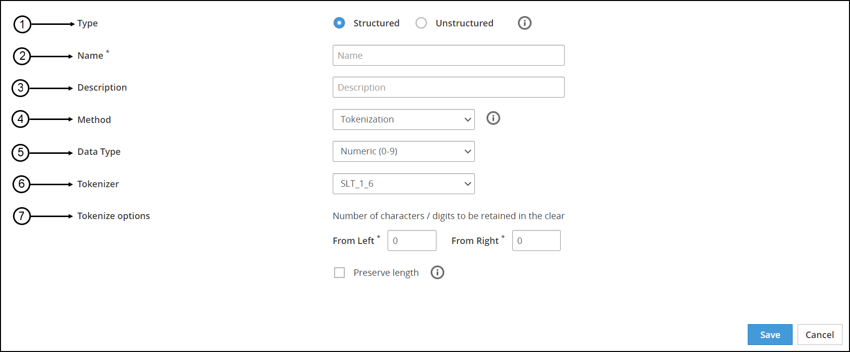
The following figure shows the New Data Element screen.
The following table provides the description for each data element available on the of the ESA Web UI.
| Callout | UI Element | Description |
|---|
| 1 | Type | Type of data element you require to create, structured or unstructured. |
| 2 | Name | Unique name identifying the data element. |
| 3 | Description | Text describing the data element. |
| 4 | Method | Tokenization, encryption, masking, and monitoring methods. |
| 5 | Data Type | If you have selected the Tokenization method, then you need to specify the data type. For example, Numeric, Alpha-Numeric, UnicodeGen2, and so on. |
| 6 | Tokenizer | If you have selected the Tokenization method, you need to select the Tokenizer. For example, SLT_1_6, SLT_2_6, SLT_1_3 and SLT_2_3. |
| 7 | Encryption Options/Tokenize Options | Based on the method selected, the tokenization or the encryption options change. |
4.1.1 - Example - Creating Token Data Elements
You create token data elements for all protectors, except for the File Protector.
This example shows how to create numeric tokenization data element that is used to tokenize numerical data.
To create a structured data element:
On the ESA Web UI, navigate to Policy Management > Data Elements & Masks > Data Elements.
Click Add New Data Element.
The New Data Element screen appears.
Select Structured from Type.
Type a unique name for the data element in the Name textbox.
The maximum length of the data element name is 55 characters.
Type the description for the data element in the Description textbox.
Select the protection method from the Method drop-down. In this example, select Tokenization.
Select the tokenization data type from the Data Type drop down. In this example, select Numeric (0-9).
For more information about the different data types, refer to the Protection Methods Reference Guide.
Select the tokenizer from the Tokenizer drop-down.
For more information about the different token elements, refer to the Protection Methods Reference Guide.
If the Tokenizer should leave characters in clear, then set the number of characters from left and from right in the From Left and From Right text boxes.
For more information on the maximum and minimum input values for these fields, refer to the section Minimum and Maximum Input Length in the Protection Methods Reference Guide.
If the token length needs to be equal to the provided input, then select the Preserve length check box.
If you select the Preserve length option, then you can also choose the behavior for short data tokenization in the Allow Short Data drop-down.
If you require short data tokenization with existing data that was previously not protected using short data enabled data element, then you must do the following:
- Unprotect the existing data with the old data element.
- Create a new data element that is enabled with short data.
- Reprotect the unprotected data with the new short data enabled data element.
For more information about length preservation and short data tokenization, refer to section Length Preserving and Short Data Tokenization in Protection Methods Reference Guide.
Click Save.
A message Data Element has been saved successfully appears.
4.1.2 - Example - Creating a FPE Data Element
Create a FPE data element.
This example shows how to create an FPE data element that is used to encrypt Plaintext Alphabet data.
To create a structured FPE data element:
On the ESA Web UI, navigate to Policy Management > Data Elements & Masks > Data Elements.
Click Add New Data Element.
The New Data Element screen appears.
Select Structured from Type.
Enter a unique name for the data element in the Name textbox.
The maximum length of the data element name is 55 characters.
Type the description for the data element in the Description textbox.
Select FPE NIST 800-38G from the Method drop-down.
Select a data type from the Plaintext Alphabet drop-down.
Configure the minimum input length from the Minimum Input Length text box.
Select the tweak input mode from the Tweak Input Mode drop-down.
For more information about the tweak input mode, refer to the section Tweak Input in the Protection Methods Reference Guide.
Select the short data configuration from the Allow Short Data drop-down.
Note: FPE does not support data less than 2 bytes, but you can set the minimum message length value accordingly.
For more information about length preservation and short tokens, refer to section Length Preserving in Protection Methods Reference Guide from the Legacy Documents section.
If you are create a short data token in a policy and then deploy the policy, the Forensics displays a policy deployment warning indicating that the data element has unsupported settings.
Enter the required input characters to be retained in the clear in the From Left and From Right text box.
For more information about this setting, refer to the section Left and Right Settings in the Protection Methods Reference Guide from the Legacy Documents section.
Configure any special numeric data handling request, such as Credit Card Number (CCN), in the Special numeric alphabet handling drop-down.
For more information about handling special numeric data, refer to the section Handling Special Numeric Data in the Protection Methods Reference Guide from the Legacy Documents section.
Click Save.
A message Data Element has been created successfully appears.
4.1.3 - Example - Creating Data Elements for Unstructured Data
You create an unstructured type of data elements for File Protector policies.
This example shows how to create an AES-256 data element that is used to encrypt a file.
To create an unstructured data element:
On the ESA Web UI, navigate to Policy Management > Data Elements & Masks > Data Elements.
Click Add New Data Element.
The New Data Element screen appears.
Select Unstructured from Type.
Type a unique name for the data element in the Name textbox.
Note: Ensure that the length of the data element name does not exceed 55 characters.
Type the required description for the data element in the Description textbox.
Select AES-256 from the Method drop-down list.
If you want to enable multiple instances of keys with the data element, then check the Use Key ID (KID) checkbox.
Click Save.
A message Data Element has been saved successfully appears.
4.2 - Working With Alphabets
An overview of the Alphabets tab in the Data Elements & Masks screen.
The Unicode Gen2 token type gives you the liberty to customize what Unicode data to protect and how the protected token value is returned. It allows you to leverage existing internal alphabets or create custom alphabets by defining Unicode code points. This flexibility allows you to create token values in the same Unicode character set as the input data.
For more information about the code points and considerations around creating alphabets, refer to the section Code Points in Unicode Gen2 Token Type in the Protegrity Protection Methods and Reference Guide.
The following figure shows the Alphabet screen.

4.2.1 - Creating an Alphabet
The following procedure describes the steps to create an alphabet.
An alphabet can include multiple alphabet templates, for example, an alphabet can be created to generate a token value, which is a mix of Numeric and Cyrillic characters.
To create an alphabet:
On the ESA Web UI, navigate to Policy Management > Data Elements & Masks > Alphabets.
Click Add New Alphabet.
The New Alphabet screen appears.
Enter a unique name for the alphabet in the Name text box.
Under the Alphabet tab, click Add to add existing alphabets or custom code points to the new alphabet.
The Add Alphabet entry screen appears.
If you plan to use multiple alphabet entries to create a token alphabet, then click Add again to add other alphabet entries.
Ensure that code points in the alphabet are supported by the protectors using this alphabet.
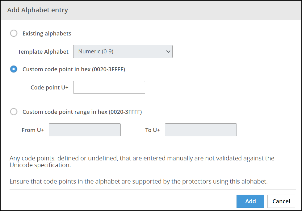
Select an existing alphabet, a custom code point, or a range of custom code points.
The following options are available for creating an alphabet.
Important: For the SLT_1_3 tokenizer, you must include a minimum of 10 code points and a maximum of 160 code points.
Important: For the SLT_X_1 tokenizer, you must include a minimum of 161 code points and a maximum of 100k code points.
| Alphabet option | Description |
|---|
| Existing Alphabets | Select one of the existing alphabets. The list includes internal and custom alphabets. |
| Custom code point in hex (0020-3FFFF) | Add custom code points that will be used to generate the token value. |
| Custom code point range in hex (0020-3FFFF) | Add a range of code points that will be used to generate the token value.
Note: When creating an alphabet using the code point range option, note that the code points are not validated.
For more information about consideration related to defining code point ranges, refer to the section Code Point Range in Unicode Gen2 Token Type in the Protegrity Protection Methods and Reference Guide. |
Click Add to add the alphabet entry to the alphabet.
Click Save to save the alphabet.
Important: Only the alphabet characters that are supported by the OS fonts are rendered properly on the Web UI.
A message Alphabet has been created successfully appears.
4.3 - Working With Masks
An overview of the Masks tab in the Data Elements & Masks screen.
Masks are a pattern of symbols and characters, that when imposed on a data field obscures its actual value to the viewer of that data. For example, you might want to mask out characters from credit cards and Social Security numbers. Masks can obscure data completely or partially. For example, a partial mask might display the last four digits of a credit card on a grocery store receipt.
For more information about the Masks option, refer to the section Masks in the Protegrity Protection Methods and Reference Guide.
The following figure shows the New Mask screen.
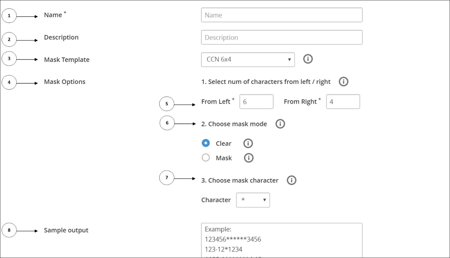
The following table provides the description for each element available on the Web UI.
| Callout | UI Element | Description |
|---|
| 1 | Name | Unique name to identify the mask. |
| 2 | Description | Text describing the mask. |
| 3 | Mask Template | Mask templates for masking the data.For more information about the mask templates, refer to Table 3-5 Mask Templates. |
| 4 | Mask Options | Following options are available to mask the data:- Mask character
- Mask Mode
- Selection of characters
|
| 5 | From Left / From Right | Select the text to be masked from left and from the right. |
| 6 | Mask Mode | If the masking is in clear or masked. |
| 7 | Mask Character | The character to mask the data. |
| 8 | Sample Output | The output based on the select template and mask mode. |
The following table shows the different mask mode templates.
| Mask Template | Mask Mode-Clear | Mask Mode-Mask |
|---|
| CCN- 6*4 | Template to retain six characters from left and four characters from right in clear.
For example,
123456******3456
123-12*1234
A123-1*******4-12 | Template to mask six characters from left and four characters from right.
For example,
******789012****
******-****
******234-123**** |
| CCN 12*0 | Template to retain 12 characters from left and no characters from right in clear.
For example,
123456789012****
123-12-1234
A123-1234-12***** | Template to mask 12 characters from left but no characters from right.
For example,
************3456
***********
************34-12
|
| CCN 4*4 | Template to retain four characters from left and four characters from right in clear.
For example,
1234********3456
123-***1234
A123*********4-12 | Template to mask four characters from left and four characters from right.
For example,
****56789012****
****12-****
****-1234-123**** |
| SSN x-4 | Template to retain no characters from left but only four characters from right in clear.
For example,
************3456
*******1234
*************4-12 | Template to mask no characters from left but four characters from right.
For example,
123456789012****
123-12-****
A123-1234-123**** |
| SSN 5-x | Template to retain five characters from left but no characters from right.
For example,
12345***********
123-1******
A123-************ | Template to mask five characters from left but no characters from right.
For example,
*****67890123456
*****2-1234
*****1234-1234-12 |
4.3.1 - Creating a Mask
The following procedure describes the steps to create a mask with the CCN-6*4 template with mask mode as clear.
To create a mask:
On the ESA Web UI, navigate to Policy Management > Data Elements & Masks > Masks.
Click Add New Mask.
The New Mask screen appears.
Enter a unique name for the mask in the Name text box.
Enter the description for the mask in the Description textbox.
Select CCN 6X4 from the Mask Template drop-down.
Select Clear from Mask Mode.
Select the masking character from the Character drop-down.
Click Save.
A message Mask has been saved successfully appears.
4.3.2 - Masking Support
The settings for masking output formats are applicable as per the following table.
| Data Element Method | Data Type | Masking Support |
|---|
| Tokenization | Numeric (0-9) | Yes |
| Alpha (a-z, A-Z) | Yes |
| Uppercase Alpha (A-Z) | Yes |
| Uppercase Alpha-Numeric (0-9, A-Z) | Yes |
| Printable | Yes |
| Date (YYYY-MM-DD, DD/MM/YYYY, MM.DD.YYYY) | No |
| DateTime | No |
| Decimal | No |
| Unicode | No |
| Unicode Base64 | No |
| Unicode Gen2 | No |
| Binary | No |
| Credit Card (0-9) | Yes |
| Lower ASCII | Yes |
| Email | Yes |
| Integer | | No |
Encryption
Algorithm: 3DES, AES-128, AES-256, CUSP 3DES, CUSP AES-128, CUSP AES-256 | | Yes |
Format Preserving Encryption (FPE)
Note:
Masking is supported only for FPE data elements without Left and Right settings and with ASCII plaintext encoding that are upgraded from the previous versions of ESA to 10.1.0 version. | | No |
| No Encryption | | Yes |
| Masking | | Yes |
4.4 - Working With Trusted Applications
An overview of Trusted Applications.
The Trusted Applications (TA) is an entity that defines which system users and applications are authorized to run the Application Protector to protect data.
Trusted Application does not support the capability of adding multiple users and applications in a single Trusted Application instance. In a Trusted Application, you can add only one application and its corresponding system user. If you want to add multiple users and applications, then you must create Trusted Application for each application and its corresponding system user.
4.4.1 - Creating a Trusted Application
The following procedure describes the steps to create a trusted application.
To make an application trusted:
On the ESA Web UI, navigate to Policy Management > Policies & Trusted Applications > Trusted Applications.
Click Add New Trusted Application.
The New Trusted Application screen appears.
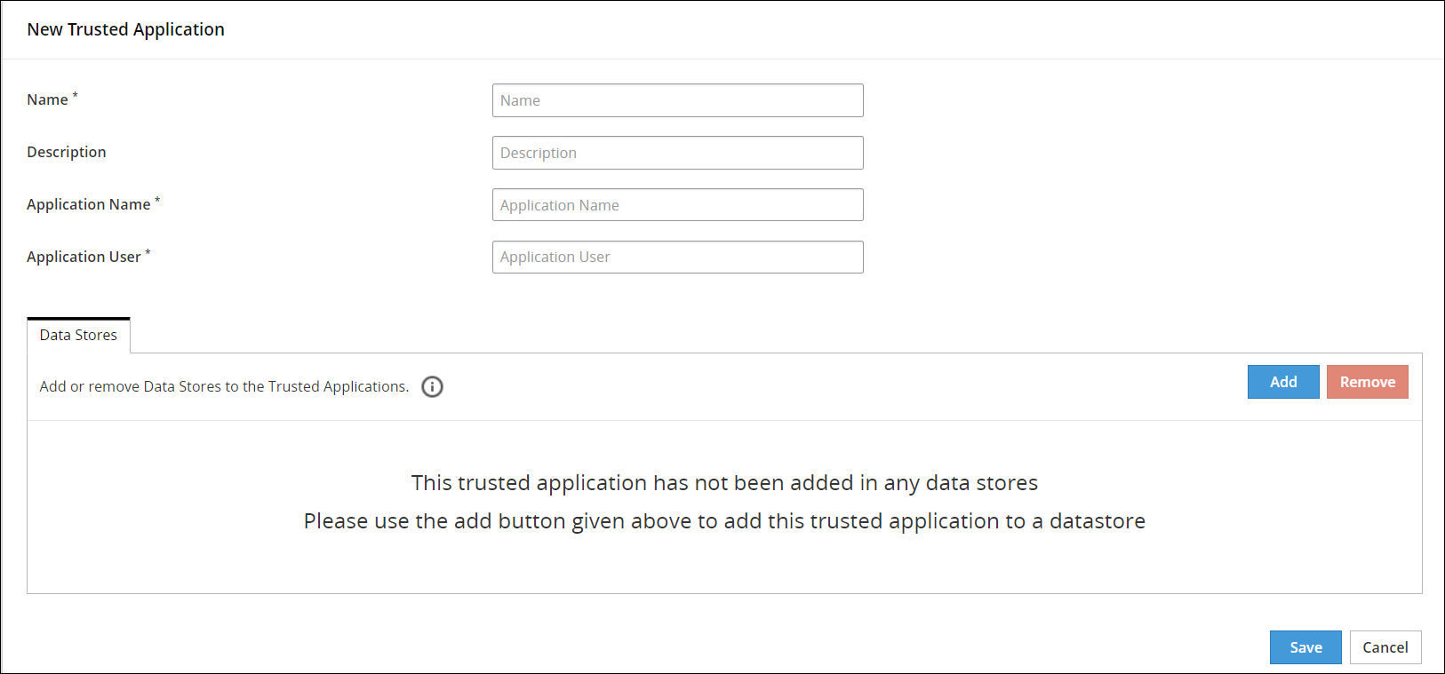
Type a unique name to the trusted application in the Name textbox.
Type the required description to the trusted application in the Description textbox.
Type the name of the application in the Application Name textbox.
The maximum length of an Application Name is up to 64 characters.
Important: In case of AP Java and AP Go applications, ensure that you specify the complete module or package name.
In the application name, you can type the asterisk (*) wild card character to represent multiple characters or the question mark (?) wild card character to represent a single character. You can also use multiple wild card characters in the application name.
For example, if you specify Test_App* as the application name, then you can use applications with names, such as, Test_App1 or Test_App123 to perform security operations.
Caution: Use wild card characters with discretion, as they can potentially lead to security threats.
Type the name of the application user in the Application User textbox.
In the application user name, you can type the asterisk (*) wild card character to represent multiple characters or the question mark (?) character to represent a single character. You can also use multiple wild card characters in the application user name.
For example, if you specify User* as the application user name, then you can have users with names, such as, User1 or User123 to perform security operations.
Caution: Use wild card characters with discretion, as they can potentially lead to security threats.
Click Save.
A message Trusted Application has been created successfully appears.
4.4.2 - Linking Data Store to a Trusted Application
You link a data store with the trusted application to specify the location where to deploy the trusted application. Using the following steps, you can link a trusted application to a data store.
To link a trusted application to a data store:
On the ESA Web UI, navigate to Policy Management > Policies & Trusted Applications > Trusted Applications.
The list of all the trusted applications appear.
Select the required trusted application.
The screen to edit the trusted application appears.
Under the Data Stores tab, click Add.
The screen to add the data stores appears.
Select the required data stores.
Click Add.
A message Select Data Stores have been added to Trusted Application successfully appears.
4.4.3 - Deploying a Trusted Application
This section describes the steps to deploy a trusted application.
Deploying a trusted application consists of the following two states:
Making the Trusted Application ready for deployment
The following procedure describes the steps to make a trusted application ready for deployment.
After you link data stores to your trusted application, it is ready to be deployed to the protector nodes.
To make a trusted application ready for deployment:
On the ESA Web UI, navigate to Policy Management > Policies & Trusted Applications > Trusted Applications.
The list of all the trusted applications appear.
Select the required trusted application.
The screen to edit the trusted application appears.
Click Ready to Deploy.
A message Trusted Application has been marked ready to deploy appears.
The Deploy action is active.
Deploying the Trusted Application
The following procedure describes the steps to deploy the trusted application.
You deploy the policy to the data store after the trusted application is ready for deployment. If no data stores are linked with the trusted application, then the deployment of the trusted application fails.
To deploy the trusted application:
On the ESA Web UI, navigate to Policy Management > Policies & Trusted Applications > Trusted Applications.
The list of all the trusted applications appear.
Select the required application that is in the ready to deploy state.
The screen to edit the trusted application appears.
Click Deploy.
A message Trusted application has been successfully deployed appears.
During deployment, the Application Protector validates the trusted application. If the validation fails, then the Protector generates an audit entry with the detailed information.
You can also deploy the trusted application by deploying the data store. In this case, all the policies and trusted applications that are linked to the data store are prepared to be distributed to the protection points.
For more information about deploying a data store, refer to Deploying Data Stores to Protectors.
4.5 - Creating a Data Store
A data store identifies one or more protectors.
You create data stores to specify the protectors in your enterprise to which you want to deploy policies and trusted applications. The protectors are identified by their IP address which must be unique across the enterprise. Using the data store, you can define the list of protector nodes that can pull the packages. A data store consists of information on policies and trusted applications. You can create a default data store that deploys polices to the protectors that are not a part of the allowed servers list of any data store. Thus, when a new protector is added that is not a part of any data store, the protector inherits the policy information pertaining to the default data store.
You cannot create data stores with the same names in the data store name. You can create only one default data store for a single instance of ESA.
To create a data store:
On the ESA Web UI, navigate to Policy Management > Data Stores.
The list of all the data stores appear.
Click Add New Data Store.
The New Data Store screen appears.
Enter a unique name identifying the data store in the Name textbox.
The maximum length of the data store name is 55 characters.
Enter the description describing the data store in the Description textbox.
Click the Select as Default Data Store option.
If a default data store already exists and you are updating another data store as the default data store, then the following message appears.
A default Data Store already exists, Please confirm to make this the new default Data Store.
Click Ok.
Click Save.
A message Data Store has been created successfully appears.
The following tabs are visible after the data store has been saved, as per the type of data store:
- The Policies and Trusted Applications tabs are visible in case of a default data store.
- The Allowed Servers, Policies, and Trusted Applications tabs are visible in case of a non-default data store.
You can also create a Data Store using the Policy Management REST API.
4.5.1 - Adding Allowed Servers for the Data Store
For a data store, you can specify the allowed servers using the Allowed Servers tab. Allowed servers specify either the IP addresses for the range of servers or a single server IP address.
Specifying Allowed Servers for the Data Store
This section describes the steps to specify allowed servers for a data store.
To specify allowed servers for a data store:
On the ESA Web UI, navigate to Policy Management > Data Stores.
The list of all the data stores appear.
From the Allowed Servers tab for the data store, click Add.
The Add Allowed Servers screen appears.
If you want to add a single server, then select Single Server and specify the server IP address.
If you want to add a range of servers, then Multiple Servers. Enter the range in the From and To text boxes.
Click Add.
The servers are added to the list
4.5.2 - Adding Policies to the Data Store
You add a policy to a data store before deploying it to remote protection points.
To add policy to a data store:
On the ESA Web UI, navigate to Policy Management > Data Stores .
The list of all the data stores appear.
Select the data store.
The screen to edit the data store appears.
Click the Policies tab.
Click Add.
The list of policies created appear.
Select the policies.
Click Add.
A message Selected Polices have been added to the Data Store successfully appears.
For more information on creating policies, refer to section Creating and Deploying Policies.
4.5.3 - Adding Trusted Applications to the Data Store
You can add a trusted application to a data store before deploying it to remote protection points.
To add trusted application to a data store:
On the ESA Web UI, navigate to Policy Management > Data Stores .
The list of all the data stores appear.
Select the data store.
The screen to edit the data store appears.
Click the Trusted Applications tab.
Click Add.
The list of trusted applications created appear.
Select the trusted applications.
Click Add.
A message Selected Trusted Applications have been added to the Data Store successfully appears.
4.6 - Working With Member Sources
The Member Sources are the source locations of users and user groups to be involved in the policies.
The users can come from the following types of sources:
- User directory, such as:
- LDAP
- Posix LDAP
- Active Directory
- Azure AD
- Database
- Teradata
- Oracle
- SQL Server
- DB2
- PostgreSQL
- File
Using these source types, you configure the connection to a directory to retrieve information on the users and the user groups available.
When you configure the connection to any member source, you can verify the following values:
- The connection parameters that you have specified are correct.
- The users and groups can be retrieved from the member source.
Click Test adjacent to the member source entry from the list or from the respective member source screen. The Test Member Source Connection dialog box displays the status with the following parameters:
- connection
- authentication
- groups
- users
Note: The password length of a member source on some platforms may have a limitation.
4.6.1 - Configuring Active Directory Member Source
You use the Active Directory type external source to retrieve information on users and user groups from an Active Directory, which organizes corporate information on users, machines, and networks in a structural database.
To create an Active Directory member source:
On the ESA Web UI, navigate to Policy Management > Roles & Member Source > Member Sources.
Click Add New Member Source.
The New Member Source screen appears.
Enter a unique name of the file member source in the Name textbox.
Type the description in the Description textbox.
Select Active Directory from the Source Type drop-down list.
The Active Directory Member Source screen appears.
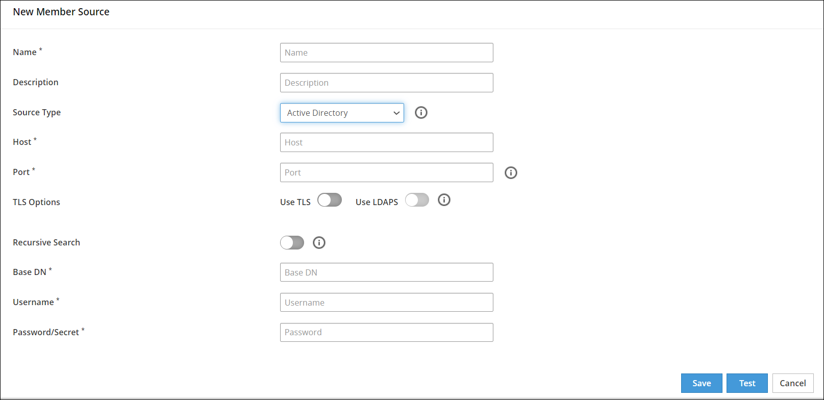
Enter the information in the directory fields.
The following table describes the directory fields for Active Directory member sources.
| Field Name | Description |
|---|
| Host | The Fully Qualified Domain Name (FQDN), or IP of the directory server. |
| Port | The network port on the directory server where the service is listening. |
| TLS Options | - The Use TLS option can be enabled to create secure communication to the directory server.
- The Use LDAPS option can be enabled to create secure communication to the directory server. LDAPS uses TLS/SSL as a transmission protocol.
Note: Selection of the LDAPS option is dependent on selecting the TLS option. If the TLS option is not selected, then the LDAPS option is not available for selection. |
| Recursive Search | The recursive search can be enabled to search the user groups in the active directory recursively. For example, consider a user group U1 with members User1, User2, and Group1, and Group1 with members User3 and User4. If you list the group members in user group U1 with recursive search enabled, then the search result displays User1, User2, User3, and User4. |
| Base DN | The base distinguished name where users can be found in the directory. |
| Username | The username of the Active Directory server. |
| Password/Secret | The password of the user binding to the directory server. |
Click Save.
A message Member Source has been created successfully appears.
4.6.2 - Configuring File Member Source
You use the File type to obtain users or user groups from a text file. These text files reference individual members and groups of members.
In Policy Management, the exampleusers.txt and examplegroups.txt are sample member source files that contain a list of users or groups respectively. These files are available on the ESA Web UI. You can edit them to add multiple user name or user groups. You can also create a File Member source by adding a custom file.
The examplegroups.txt has the following format.
[Examplegroups]
<groupusername1>
<groupusername2>
<groupusername3>
Note: Ensure that the file has read permission set for Others.
Important: The exampleusers.txt or examplegroups.txt files do not support the Unicode characters, which are characters with the \U prefix.
Viewing the List of Users and Groups in the Sample Files
This sections describes the steps to view the list of users and groups in the sample files.
To view list of users and groups in the sample files:
On the ESA Web UI, navigate to Settings > Systems > Files.
Click View, corresponding to exampleusers.txt or examplegroups.txt under Policy Management-Member Source Service User Files and Policy Management-Member Source Service Group Files respectively.
The list of users in the exampleuser.txt file or examplegroups.txt file appear.
Creating File Member Source
This section describes the procedure on how to create a file member source.
To create file member source:
On the ESA Web UI, navigate to Policy Management > Roles & Member Source > Member Sources.
Click Add New Member Source.
The New Member Source screen appears.
Enter a unique name of the file member source in the Name textbox.
Type the description in the Description textbox.
Select File from the Source Type drop-down list.
Select Upload file from the User File drop-down list.
Click the Browse..  icon to open the file browser.
Select the user file.
Click Upload File  icon.
icon.
A message User File has been uploaded successfully appears.
Select Upload file from the Group File drop-down list.
Click the Browse..  icon to open the file browser.
Select the group file.
Click Upload File  icon.
icon.
A message Group File has been uploaded successfully appears.
Click Save.
A message Member Source has been created successfully appears.
4.6.3 - Configuring LDAP Member Source
You use the Lightweight Directory Access Protocol (LDAP) type user source to retrieve information on users and user groups from a LDAP Server. The LDAP Server facilitates users and directory services over an IP network and provides Web Services for Application Protector.
To create an LDAP member source:
On the ESA Web UI, navigate to Policy Management > Roles & Member Source > Member Sources.
Click Add New Member Source.
The New Member Source screen appears.
Enter a unique name of the file member source in the Name textbox.
Type the description in the Description textbox.
Select LDAP from the Source Type drop-down list.
The LDAP Member Source screen appears
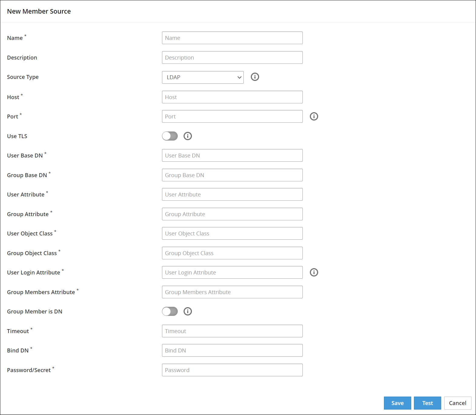
Enter the information in the LDAP member source fields.
The following table describes the directory fields for LDAP member sources.
| Field Name | Description |
|---|
| Host | The Fully Qualified Domain Name (FQDN), or IP of the directory server. |
| Port | The network port on the directory server where the service is listening. |
| Use TLS | The TLS is enabled to create a secure communication to the directory server. LDAPS, which is deprecated, is no longer the supported protocol. TLS is the only supported protocol. |
| User Base DN | The base distinguished name where users can be found in the directory. The user Base DN is used as the user search criterion in the directory. |
| Group Base DN | The base distinguished name where groups can be found in the directory. The group base dn is used as a group search criterion in the directory. |
| User Attribute | The Relative Distinguished Name (RDN) attribute of the user distinguished name. |
| Group Attribute | The RDN attribute of the group distinguished name. |
| User Object Class | The object class of entries where user objects are stored. Results from a directory search of users are filtered using user object class. |
| Group Object Class | The object class of entries where group objects are stored. Results from a directory search of groups are filtered using group object class. |
| User Login Attribute | The attribute intended for authentication or login. |
| Group Members Attribute | The attribute that enumerates members of the group. |
| Group Member is DN | The members may be listed using their fully qualified name, for example, their distinguished name or as in the case with the Posix user attribute (cn) value. |
| Timeout | The timeout value when waiting for a response from the directory server. |
| Bind DN | The DN of a user that has read access, rights to query the directory. |
| Password/Secret | The password of the user binding to the directory server |
Parsing users from a DN instead of querying the LDAP server: By default, a user is not resolved by querying the external LDAP server. Instead, the user is resolved by parsing the User Login Attribute from the Distinguished Name that has been initially retrieved by the Member Source Service.
This option is applicable only if the Group Member is DN option is enabled while configuring the Member Source. In this case, the members must be listed using their fully qualified name, such as their Distinguished Name. If the ESA is unable to parse the DN or the DN is not available in the specified format, the user is resolved by querying the external LDAP server.
Click Save.
A message Member Source has been created successfully appears.
4.6.4 - Configuring POSIX Member Source
You use Posix LDAP to retrieve information on users and user groups from an internal LDAP Server that uses the Posix schema.
You can retrieve users and user groups from any external LDAP and Posix LDAP. The internal LDAP available on ESA, uses the Posix schema. Thus, when using ESA, it is recommended to use Posix LDAP to configure the connection with the internal ESA LDAP.
To create a Posix LDAP member source:
On the ESA Web UI, navigate to Policy Management > Roles & Member Source > Member Sources.
Click Add New Member Source.
The New Member Source screen appears.
Enter a unique name of the file member source in the Name textbox.
Type the description in the Description textbox.
Select Posix LDAP from the Source Type drop-down list.
The Posix LDAP Member Source screen appears.
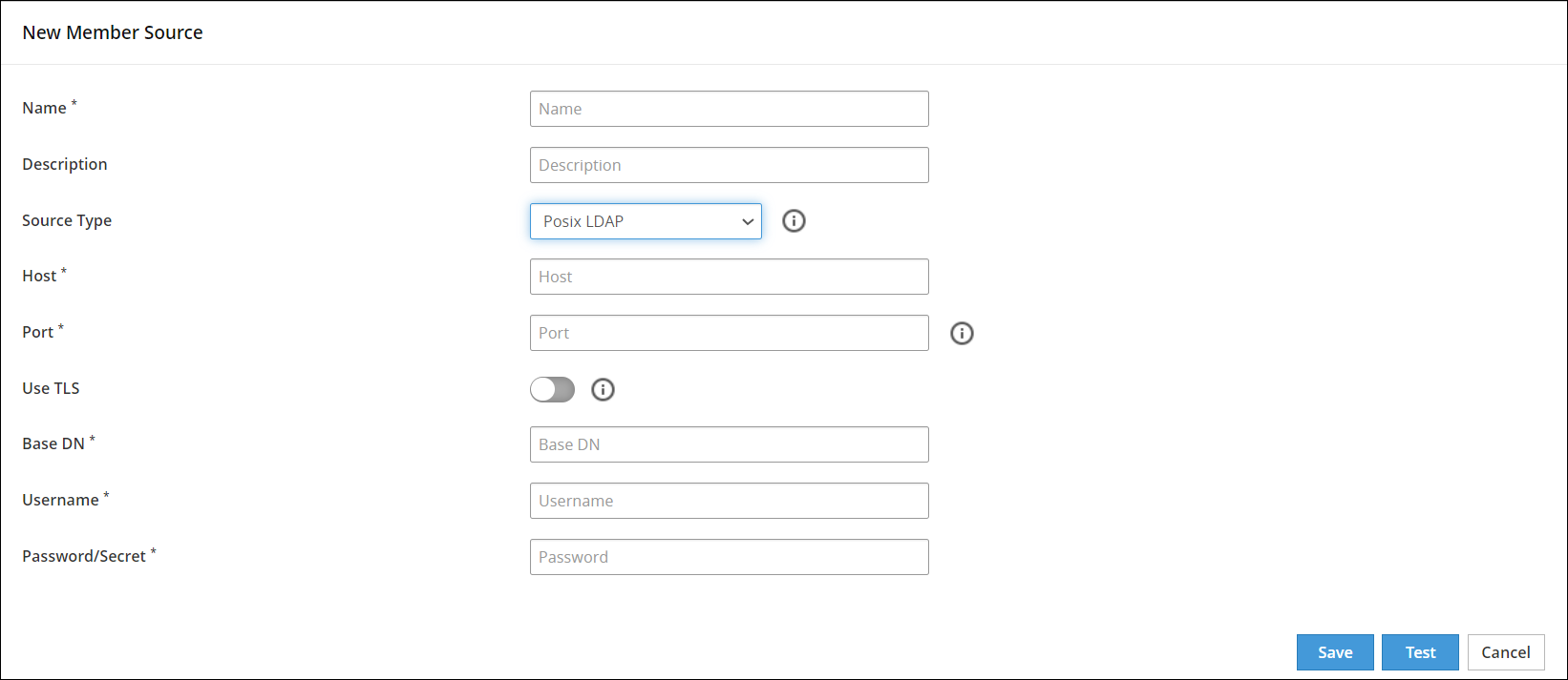
Enter the information in the directory fields.
The following table describes the directory fields for Posix LDAP member source.
| Field Name | Description |
|---|
| Host | The Fully Qualified Domain Name (FQDN), or IP of the directory server. |
| Port | The network port on the directory server where the service is listening. |
| Use TLS | The TLS can be enabled to create a secure communication to the directory server. |
| Base DN | The base distinguished name where users can be found in the directory. |
| Username | The username of the Posix LDAP server. |
| Password/Secret | The password of the user binding to the directory server. |
Click Save.
A message Member Source has been created successfully appears.
4.6.5 - Configuring Azure AD Member Source
You use the Azure AD type external source to retrieve information for users and user groups from an Azure AD, which organizes corporate information on users, machines, and networks in a structural database.
To create an Azure AD member source:
On the ESA Web UI, navigate to Policy Management > Roles & Member Sources > Member Sources.
Click Add New Member Source.
The New Member Source screen appears.
Enter a unique name of the Azure AD member source in the Name textbox.
Type the description in the Description textbox.
Select Azure AD from the Source Type drop-down list.
The Azure AD Member Source screen appears.
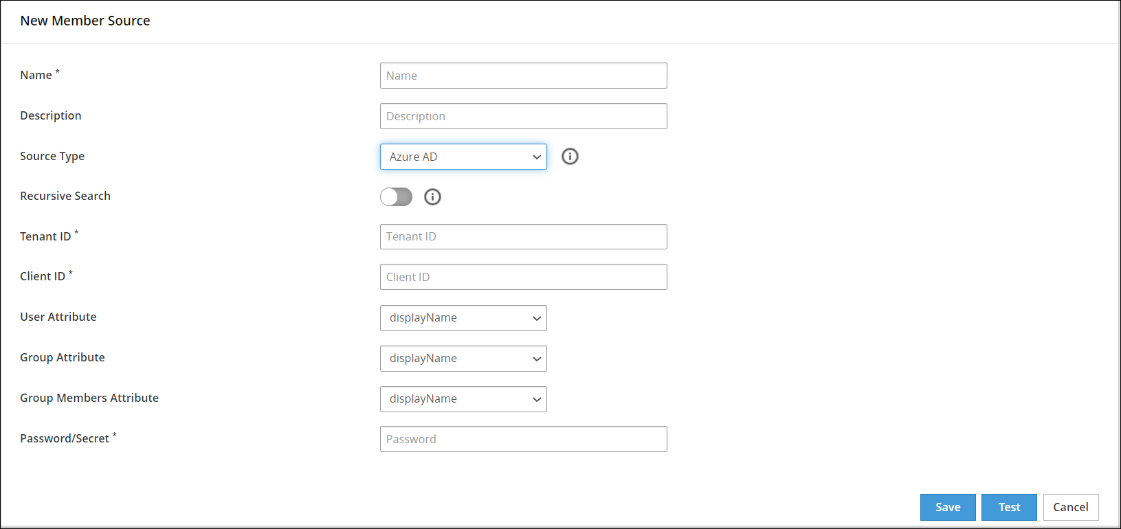
Enter the information in the directory fields.
The following table describes the directory fields for the Azure Active Directory member sources.
| Field Name | Description |
|---|
| Recursive Search | The recursive search can be enabled to search the user groups in the Azure AD recursively. |
| Tenant ID | The unique identifier of the Azure AD instance |
| Client ID | The unique identifier of an application created in Azure AD |
| User Attribute | The Relative Distinguished Name (RDN) attribute of the user distinguished name. The following user attributes are available:
- displayName - The name displayed in the address book for the user.
- userPrincipalName - The user principal name (UPN) of the user.
- givenName - The given name (first name) of the user.
- employeeId - The employee identifier assigned to the user by the organization.
- id - The unique identifier for the user.
- mail - The SMTP address for the user.
- onPremisesDistinguishedName - Contains the on-premises Active Directory distinguished name (DN).
- onPremisesDomainName - Contains the on-premises domainFQDN, also called dnsDomainName, synchronized from the on-premises directory.
- onPremisesSamAccountName - Contains the on-premises samAccountName synchronized from the on-premises directory.
- onPremisesSecurityIdentifier - Contains the on-premises security identifier (SID) for the user that was synchronized from the on-premises setup to the cloud.
-onPremisesUserPrincipalName - Contains the on-premises userPrincipalName synchronized from the on-premises directory.
- securityIdentifier - Security identifier (SID) of the user, used in Windows scenarios. |
| Group Attribute | The RDN attribute of the group distinguished name. The following group attributes are available:
- displayName - The display name for the group.
- id - The unique identifier for the group.
- mail - The SMTP address for the group.
- onPremisesSamAccountName - Contains the on-premises SAM account name synchronized from the on-premises directory.
- onPremisesSecurityIdentifier - Contains the on-premises security identifier (SID) for the group that was synchronized from the on-premises setup to the cloud.
- securityIdentifier - Security identifier of the group, used in Windows scenarios. |
| Group Members Attribute | The attribute that enumerates members of the group.
Note: Ensure to select the same Group Members Attribute as the User Attribute.
The following group members attributes are available:
- displayName - The name displayed in the address book for the user.
- userPrincipalName - The user principal name (UPN) of the user.
- givenName - The given name (first name) of the user.
- employeeId - The employee identifier assigned to the user by the organization.
- id - The unique identifier for the user.
- mail - The SMTP address for the user.
- onPremisesDistinguishedName - Contains the on-premises Active Directory distinguished name (DN).
- onPremisesDomainName - Contains the on-premises domainFQDN, also called dnsDomainName, synchronized from the on-premises directory.
- onPremisesSamAccountName - Contains the on-premises samAccountName synchronized from the on-premises directory.
- onPremisesSecurityIdentifier - Contains the on-premises security identifier (SID) for the user that was synchronized from the on-premises setup to the cloud.
- onPremisesUserPrincipalName - Contains the on-premises userPrincipalName synchronized from the on-premises directory.
- securityIdentifier - Security identifier (SID) of the user, used in Windows scenarios.
|
| Password/Secret | The client secret is the password/secret of the Azure AD application. |
Click Save.
A message Member Source has been created successfully appears.
4.6.6 - Configuring Database Member Source
This section explains the process to configure a Database Member Source.
You use the Database type to obtain users from database, such as, SQL Server, Teradata, DB2, PostgreSQL, or Oracle. An ODBC connection to the database must be setup to retrieve user information.
The following table describes the connection variable settings for the databases supported in Policy Management.
| Database Type | Database |
|---|
| SQLSERVER | System DSN Name (ODBC) For example, SQLSERVER_DSN. |
| TERADATA | System DSN Name (ODBC) For example, TD_DSN. |
| ORACLE | Transport Network Substrate Name (TNSNAME). |
| DB2 | System DSN Name (ODBC) For example, DB2DSN. |
| POSTGRESQL | System DSN Name For example, POSTGRES. |
Creating Database Member Source
This section describes the procedure on how to create a database member source.
To create a Database Member Source:
On the ESA Web UI, navigate to Policy Management > Roles & Member Source > Member Sources.
Click Add New Member Source.
The New Member Source screen appears.
Enter a unique name for the file member source in the Name text box.
Type the description in the Description text box.
Select Database from the Source Type drop-down list.
Select one of the following database from the Source drop-down list.
- Teradata
- Oracle
- SQL Server
- DB2
- PostgreSQL
To enable the usage of a custom data source name, switch the Use Custom DSN toggle.
- Enter the custom data source name in the DSN text box.
- Ensure that the specified DSN is present in the odbc.ini configuration file located in the /opt/protegrity/mbs/conf/ directory.
If you are selecting the Oracle database as the source database, then enter the service name in the Service Name text box.
Note: This step is applicable for the Oracle database only.
If you are not using Custom DSN, then the following steps are applicable.
Enter the database name in the Database text box.
Enter the host name in the Host text box.
Enter the port to connect to the database in the Port text box.
Enter the username in the Username text box.
Enter the password in the Password text box.
Click Save.
The message Member Source has been created successfully appears.
4.7 - Working with Roles
An overview of roles in Policy Management.
The authorization criteria for each user is defined in form of members of roles. Roles determine and define the unique data access privileges for each member. Each role is associated with a level of authorization granted to all its members, including specific data access privileges.
The following figure shows the New Role screen.
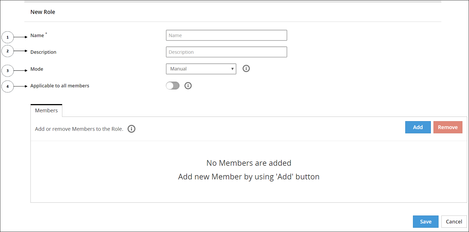
The following table provides the description for each element available on the of the Web UI.
| Callout | UI Element | Description |
|---|
| 1 | Name | The unique name of the role. |
| 2 | Description | The description of the role. |
| 3 | Mode | The refresh mode for that role. For more information about refresh mode, refer to section Mode Types for a Role. |
| 4 | Applicable to all members | If enabled, the specific role will be applied to any member that does not belong to any other role. |
4.7.1 - Creating a Role
This section describes the steps to create a role.
To create a role:
On the ESA Web UI, navigate to Policy Management > Roles & Member Source > Roles.
Click Add New Role.
The New Role screen appears.
Enter a unique name for the role in the Name textbox.
Note: Ensure that the length of the role name does not exceed 55 characters.
Enter the required description for the role in the Description textbox.
In the Mode drop-down, select a refresh mode.
For more information about about mode types for a role, refer to section Mode Types for a Role.
If you want to apply this role to all members in all the member sources, click Applicable to all members. If enabled, the role is applied to all members in users or groups that do not belong to any other role.
Click Save.
4.7.2 - Mode Types for a Role
The mode types for a role defines how roles are synchronized and then updated in a security policy. The users are refreshed in the policy as per the mode settings.
The modes that are available are Automatic, Semi-automatic, and Manual.
The synchronization of members can be described as follows:
- Synchronization between Hub Controller and Member Source: The Member Source component is responsible for synchronization of the latest changes made in the external sources, such as LDAP, AD, file, or database. In the ESA, the HubController synchronizes with the Member Source to update the policy with any changes detected in roles once in an hour.
- Automatic Mode
- In automatic mode, groups from the member sources are synchronized periodically without user intervention. The synchronization happens every one hour. The updated policy is deployed automatically after the synchronization.
- Semi-Automatic Mode
- Semi-Automatic mode is similar to the automatic mode with the exception that you must synchronize the groups manually. The updated policy is deployed automatically after the manual synchronization.
For a new member added to a group, you can manually synchronize the changes by setting the mode to semi-automatic. Then, you can use the Synchronize Members button from the Members tab of a Role screen.
- Manual Mode
- The roles with mode type as Manual can accept both groups and users. You must manually synchronize the groups. After manual synchronization of members, you must set the policy as Ready to Deploy followed by deploying the policy manually.
For a new member added to a group, you can manually synchronize the changes by clicking the Synchronize Members button from the Members tab of a Role screen.
Note: If a user having the same name but with different letter case appears in multiple roles within a policy, then it can cause permission issues when the policy is deployed. This can happen if the user has different permissions in each role.
To avoid this issue, when the members are automatically synchronized, and users having the same name but different letter case appear in roles, an error is generated. This error appears in the Notifications section of the ESA dashboard to inform you that such conflicting users have been found. The error specifies the correlation ID of the HubController audit log that has been generated. To identify the conflicting users, navigate to the Discover page in the Audit Store Dashboards and search for the specified correlation ID.
4.7.3 - Adding Members to a Role
Users are assigned to a Role by adding them as members under the role. The member types are categorized as specific users or a group of users.
This section describes the steps to add members to a role.
To add members to a role:
On the ESA Web UI, navigate to Policy Management > Roles & Member Source > Roles.
Click on the role name link to which you want to add members.
The selected role screen appears.
In the Members tab, click Add.
The Add Members screen appears.
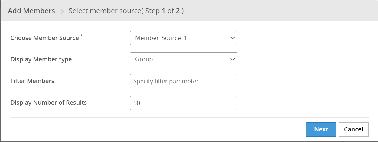
In the Choose Member Source drop-down, select the Member Source.
In the Display Member Type drop-down, select the member type.
For Automatic or Semi-Automatic mode, it causes the removal of members of type Users from the role. The Display Member Type drop-down is disabled in this case with default Group member type.
Enter the filter parameter in the Filter Members text box.
It accepts characters such as ‘*’ to display all results or word search to search with a word.
For more information about filtering members from AD and LDAP member sources, refer to the sections Filtering Members from AD and LDAP Member Sources and Filtering Members from Azure AD Member Source.
Select the number of display results in the Display Number of Results spin box.
Click Next.
The step 2 of Add Members dialog box appears.
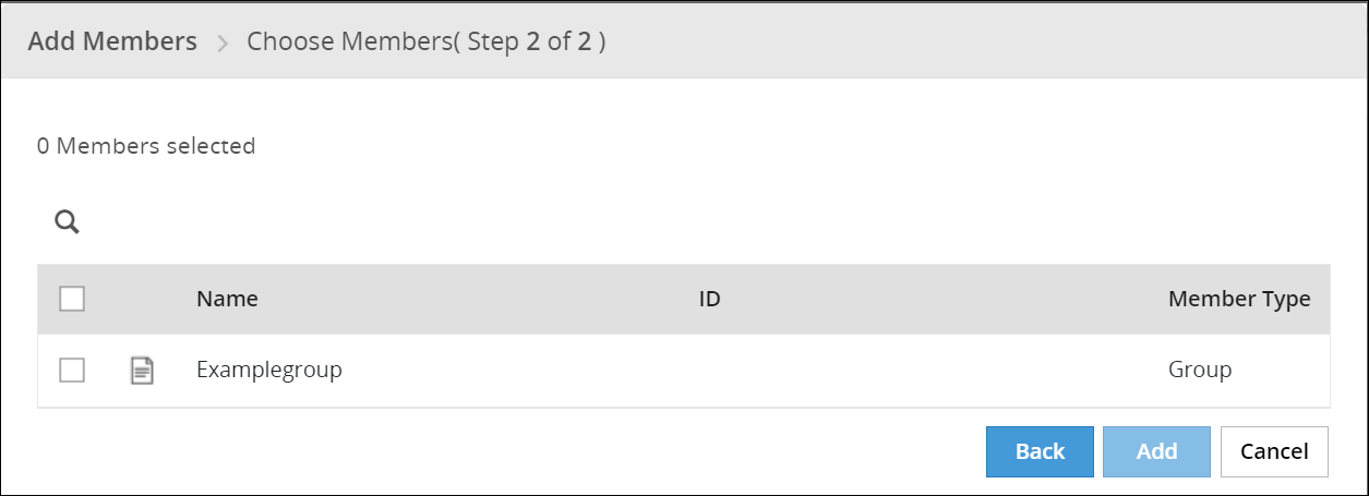
Note: The ID column displays the unique identifier for the Azure AD, Posix LDAP and Active Directory member sources.
Select the check box next to each member you want to add.
Click Add.
The selected members are added to the role.
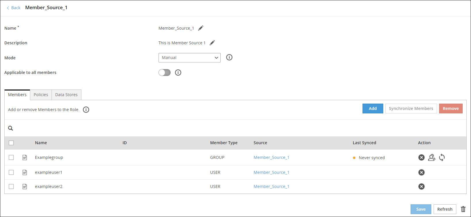
Note: The ID column displays the unique identifier for the Azure AD, Posix LDAP and Active Directory member sources.
Click Save to save the role.
In addition to the Members tab, you can find:
- Policies: It displays all the policies that are linked to this role.
- Data Stores: It displays all the data stores that are linked to this role.
4.7.3.1 - Filtering Members from AD and LDAP Member Sources
When adding members to a role, you can filter members from the member sources, such as, AD, LDAP, or POSIX LDAP. The filtering mechanism uses search filters based on the criteria for filtering the members from AD or LDAP. The search filters help you to query the member sources to fetch the exact results that you are looking for.
The following table lists some examples using different AD and LDAP search criteria to filter the members.
| Search Criteria | Description |
|---|
| * | Retrieves all users and groups |
| Character or word search | Retrieves the results that contain the specified character or word |
| (cn=*protegrity*) | Retrieves all common names that contain the term protegrity in it |
| (sn=abc*) | Retrieves all surnames that starts with abc |
| (objectClass=*) | Retrieves all the results |
| (&(objectClass=user)(!(cn=protegrity))) | Retrieves all the users without the common name as protegrity |
| (&(cn=protegrity)(objectClass=user)(email=*)) | Retrieves all the users with an email attribute and with common name as protegrity |
| (!(email=*)) | Retrieves all the users without an email attribute |
| (&(objectClass=user)(| (cn=protegrity*)(cn=admin*))) | Retrieves all the users with common name that starts with protegrity or admin |
If the input in the search filter includes special characters, then you must use the escape sequence in place of the special character to make it a valid input in the search filters.
The following table lists the escape sequence for each of the special characters.
| ASCII Character | Escape Sequence |
|---|
| ( | \28 |
| ) | \29 |
| * | \2A |
| \ | \5C |
The following table lists some examples of search filters with the usage of escape sequences to include special characters in the search input.
| Input with Special Character | Input with Escape Sequence | Description |
|---|
| (cn=protegrity*)) | (cn=protegrity\2A\29) | The search filter retrieves the values that contain protegrity*)
In this case, the parenthesis requires an escape sequence because it is unmatched. |
| (cn= abc (xyz) abc) | | The search filter retrieves the values that contain abc (xyz) abc
In this case, the escape sequence is not required as the parenthesis are matched. |
4.7.3.2 - Filtering Members from Azure AD Member Source
When adding members to a role, you can filter members from the Azure AD member source. The filtering mechanism uses search filters based on the criteria for filtering the members from the Azure AD. The search filters help you to query the member source to fetch the exact results that are required.
The following table lists an example for the Azure AD search criteria to filter the members.
| Search Criteria | Description |
|---|
| startsWith(displayname,‘xyz’) | Retrieves all groups and users that start with xyz
Note: For more information and examples about the filter criteria for the Azure AD member source, search for the text Advanced query capabilities on Azure AD on Microsoft’s Technical Documentation site at:
https://learn.microsoft.com/en-us/docs/ |
4.7.4 - Synchronizing, Listing, or Removing Members in a Role
When you add or delete members in a group, you need to synchronize the members in a role to reflect the updates done to the group.
The following figure explains the steps to synchronize, list or remove members in a role.
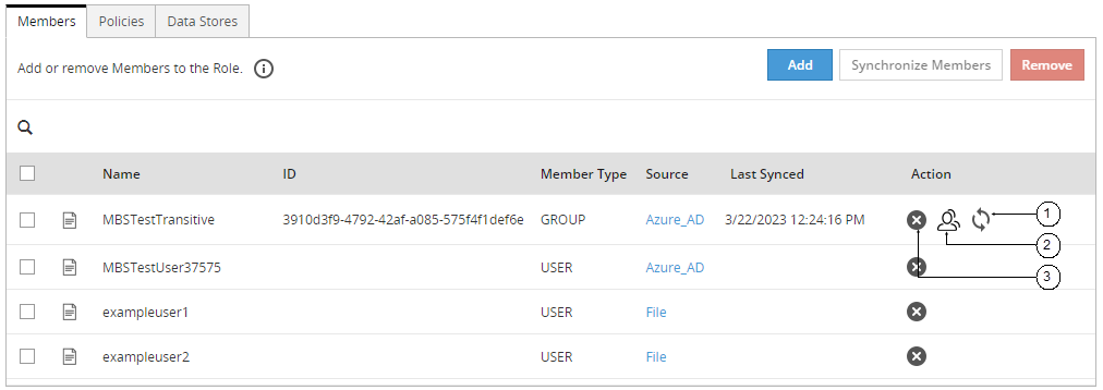
Note: The ID column displays the unique identifier for the Azure AD, Posix LDAP and Active Directory member sources.
The following table provides the description for each element available on the of the Web UI.
| Callout | Task Name | Steps |
|---|
| 1 | Synchronize Members | 1. Select the role you want to update by clicking on it in the ESA Web UI, under Policy Management > Roles & Member Sources > Roles.
2. Click the Synchronize Members  icon. icon.
A status message appears. |
| 2 | List Group Members | 1. Select the role you want to update by clicking on it in the ESA Web UI, under Policy Management > Roles & Member Sources > Roles.
2. Click the List Group Members  . .
The dialog box appears with the list of all members in the group. |
| 3 | Remove Members | 1. Select the role you want to update by clicking on it in the ESA Web UI, under Policy Management > Roles & Member Sources > Roles.
2. Click Remove.
A confirmation dialog box appears.
3. Click Ok. |
4.7.5 - Searching User
This section provides information on how to search a user.
The Search Member screen from the Roles & Member Sources screen provides a way to search the users with the associated roles. It also provides additional details like user added time, role and member source to which it belongs to.
For example, if you want to check the role of a user with its member source, then the search results can provide you a way to troubleshoot or check the user-role mapping.
To search a member:
On the ESA Web UI, navigate to Policy Management > Roles & Member Source > Search Member.
Enter the search criteria in the Member Name textbox.
For more on valid search criteria, refer to Search Criteria.
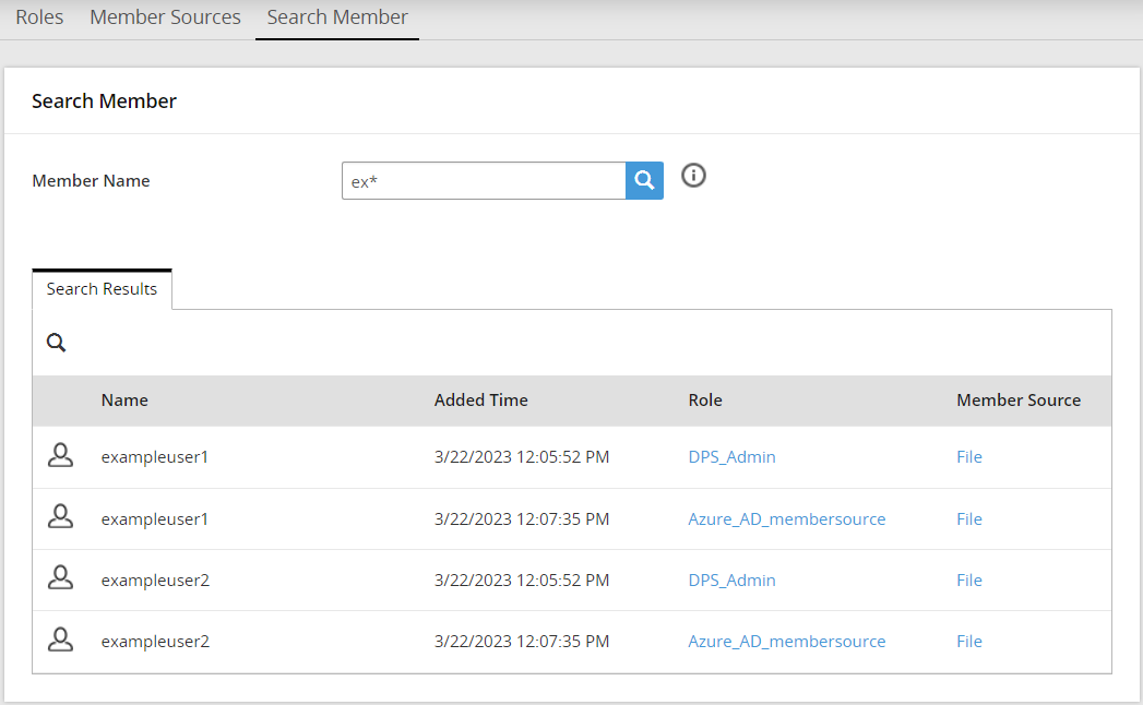
Click Search  .
.
The search results appear.
- Search Criteria
- Consider the following scenario:
- You have created a file member source named MemberSource1 which includes:
- Group File named examplegroups with users examplegroupuser1 and examplegroupuser2
- User File named exampleusers with users exampleuser1 and exampleuser2
- You have created a role named Role1.
- You have added all users from MemberSource1 to Role1.
For the given example, the following table lists the search results with different search criteria.
Table: Search Criteria
| Search Criteria | Description | Output |
|---|
| Wild card | Search with ‘*’ | It displays all the members. |
| Character search | Character search Search with ‘1’ | It displays examplegroupuser1 and exampleuser1. |
| Word search | Search with ‘group’ | It displays examplegroupuser1 and examplegroupuser2. |
You can perform additional actions on the search results such as:
- Clicking on the Role or Source column values redirects you to the Roles or Member Sources page respectively.
- Members can be sorted based on Name, Added Time, Role or Source columns.
- Search results also can be filtered with another search option, which is provided in the search results.
5 - Creating and Deploying Policies
Policies contain detailed and comprehensive security definitions. Policies are distributed to the locations in your enterprise set up for policy enforcement.
The following figure displays a sample policy.
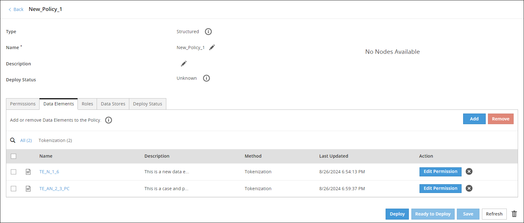
You can add data elements, roles, link the policy to a data store, and deploy the policy to the protector nodes. You also set different permissions for the content restrictions for a policy.
You can create two types of policies:
- Structured Policy - Policy that supports column-level database protection and integrates policies into applications using an API. This policy type contains only structured data elements.
- Unstructured Policy - Policy that provides support for file protection. This policy type contains only unstructured data elements. It is only supported for File Protectors. The unstructured policy is not applicable for 10.0.0 protectors.
A policy is in one of the following states:
- Ready to Deploy – The policy is created with the required information and ready for deployment.
- Deployed – The policy is ready to be distributed to the protectors.
You can modify a policy at any point in time. If a policy that is deployed is modified, then the policy returns to the Ready to Deploy state.
The Deploy Status is only applicable for 9.x.x.x protectors and earlier. It is not applicable for 10.0.0 protectors and later.
For 10.0.0 protectors and later, you can access this information from the Protegrity Dashboard.
The Policy Management Web UI is primarily used to create policies and related metadata.
5.1 - Creating Policies
Use the Policy Management Web UI to create structured and unstructured policies.
Creating a Structured Policy
This section describes the steps to create a structured policy.
To create a structured policy:
On the ESA Web UI, navigate to Policy Management > Policies & Trusted Applications > Policies.
The list of all the policies appears.
Click Add New Policy.
The New Policy screen appears.
Select Structured from Type.
Type a unique name for the policy in the Name textbox.
Note: The maximum length of the policy name is 55 characters.
Type the description for the policy in the Description textbox.
Under the Permissions tab, select the required permissions.
For more information about adding permissions, refer to
Adding Permissions to Policy.
Under the Data Elements tab, add the required data elements.
For more information about adding data elements, refer to Working with Data Elements.
Under the Roles tab, add the required roles.
For more information about adding roles, refer to Working with Roles.
Under the Data Stores tab, add the required Data Stores.
For more information about adding data stores, refer to Working with Data Stores.
Click Save.
A message Policy has been created successfully appears.
Creating an Unstructured Policy
This section describes the steps to create an unstructured policy.
To create an unstructured policy:
On the ESA Web UI, navigate to Policy Management > Policies & Trusted Applications > Policies.
The list of all the policies appear.
Click Add New Policy.
The New Policy screen appears.
Select Unstructured from Type.
Type a unique name for the policy in the Name textbox.
The maximum length of the policy name is 55 characters.
Type the description for the policy in the Description textbox.
Under the Permissions tab, select the required permissions.
For more information about adding permissions, refer to Adding Permissions to Policy.
Under the Data Elements tab, add the required data elements.
For more information about adding data elements, refer to Working with Data Elements.
Under the Roles tab, add the required roles.
For more information about adding roles, refer to Working with Roles.
Under the Data Stores tab, add the required Data Stores.
For more information about adding data stores, refer to Working with Data Stores.
Click Save.
A message Policy has been created successfully appears.
5.2 - Adding Data Elements to Policy
This section discusses about how to add data elements to policy.
Adding Data Elements for Structured Policies
This section describes the steps to add data elements for structured policies.
To add data elements for structured policies:
On the ESA Web UI, navigate to Policy Management > Policies & Trusted Applications > Policies.
The list of all the policies appear.
Select the policy.
The screen to edit the policy appears.
Click the Data Elements tab.
Click Add.
The list of all the available data elements appears.
Select the data elements.
Click Add.
A message Selected Data Elements have been added to the policy successfully appears.
Adding Data Elements for Unstructured Policies
This section describes the steps to add data elements for unstructured policies.
To add data elements for unstructured policies:
On the ESA Web UI, navigate to Policy Management > Policies & Trusted Applications > Policies.
The list of all the policies appear.
Select the policy.
The screen to edit the policy appears.
Click the Data Elements tab.
Click Add.
The list of data elements created for unstructured data appears.
Select the data elements.
Click Add.
A message Selected Data Elements have been added to the policy successfully appears.
5.3 - Adding Roles to Policy
This section discusses about how to add roles to a policy and then how to customize the permissions for individual roles.
Adding Roles to Policies
You add roles to a policy to enforce user access to data. The roles can be set up to enable granular access control on the sensitive enterprise data. You can add one or more roles to a policy.
To add roles to policies:
On the ESA Web UI, navigate to Policy Management > Policies & Trusted Applications > Policies.
The list of all the policies appear.
Select the policy.
The screen to edit the policy appears.
Click the Roles tab.
Click Add.
The list of roles created appears.
Select the roles.
Click Add.
A message Selected Roles have been added to the policy successfully appears.
5.4 - Adding Permissions to Policy
Permissions are applied restrictions to access sensitive data. Use the Policy Management Web UI or the DevOps API to add permissions to a policy.
Using the policy permissions, the system can determine what is returned to a user who wants to view protected data. If the user has the appropriate permissions, then the data gets decrypted or detokenized. If permission is denied, then a NULL value is returned by default. Depending on your data element and policy settings, the system can instead return a no-access value (such as Exception or Protected value). The permissions are always defined in the context of a roles and a data element.
You can set a no-access value, such as Exception or Protected value, through editing the permission settings for a role or a data element.
For more information about editing the permission settings of a role or data element, refer to the Customizing Permissions for Data Element in a Policy or Customizing Permissions for Role in a Policy.
The following table describes the different permissions that you can set for structured data.
| Permission | Options | Permission Description |
|---|
| Content | Unprotect | Allow members to get protected data in cleartext. |
| Protect | Allow members to add and protect the data.
Note: From 10.1.0, if you have selected the HMAC-SHA256 data elements, then only the Protect option is enabled. The other options, such as, Reprotect and Unprotect are grayed out. |
| Reprotect | Allow members to reprotect the protected data with a new data element. |
The following table describes the permissions that you can set for an unstructured data. These permissions are only applicable for File Protector.
| Permission | Options | Permission Description |
|---|
| Content | Unprotect | Allow members to get protected data in cleartext. |
| Protect | Allow members to add data and protect it as needed. | |
| Reprotect | Allow members to reprotect the protected data with a new data element. | |
| Object | Create | Allow members to create a file or directory. |
| Admin Permissions | Manage Protection | Allow members to add or remove protection. |
No Access Permissions
The following table describes the no-access permissions that can be set for a role or a data element if the Unprotect access permission is not assigned to a user.
| No Access Permission | Permission Description |
|---|
| Null | A null value is returned when the user tries to access the data. |
| Protected Value | The tokenized or encrypted value is returned when the user tries to access the data. |
| Exception | An exception is returned when the user tries to access the data. |

For more information about how no-access permissions work for users in multiple roles, refer to the section .
No-Access Permissions for Users in Multiple Roles.
You can also set permissions or rules using the Policy Management REST API.
Setting Default Permissions for a Policy
This section describes the steps to set the default permissions for a policy.
To set default permissions for a policy:
On the ESA Web UI, navigate to Policy Management > Policies & Trusted Applications > Policies.
The list of all the policies appear.
Select the required policy.
The screen to edit the policy appears.
Click the Permissions tab.
The following screen appears.

Select the required permissions.
For more information about the permissions, refer to the tables Permissions for Structured Data and Permissions for Unstructured Data.
Click Save.
The permissions are set for the policy.
Customizing Permissions for Data Elements in a Policy
You can edit the permissions for an individual data element. When you edit the permissions for a data element, then you change the permissions for the roles associated with the data element.
To customize permissions for data element in a policy:
On the ESA Web UI, navigate to Policy Management > Policies & Trusted Applications > Policies.
The list of all the policies appear.
Select the required policy.
The screen to edit the policy appears.
Click the Data Elements tab.
Click Edit Permissions.
The screen to update the permissions for the role appears.
Select the required permissions.
Note: If you are using masks with any data element, then ensure that masks are created before editing permissions.
Click Save.
A message Permissions have been updated successfully appears.
Note: The customized permissions, if any, override the default permissions for any policy.
Customizing Permissions for Roles in a Policy
You can edit the permissions for individual roles. When you edit the permissions for a role, then you change the permissions for the data elements associated with the role.
To customize permissions for role in a policy:
On the ESA Web UI, navigate to Policy Management> Policies & Trusted Applications> Policies.
The list of all the policies appear.
Select the policy.
The screen to edit the policy appears.
Click the Roles tab.
Click Edit Permissions.
The screen to update the permissions for the role appears.
Select the permissions.
Click Save.
A message Permissions have been updated successfully appears.
Note: The customized permissions, if any, override the default permissions for any policy.
5.4.1 - Permission Conflicts and Collision Behavior
Policy users can be assigned to multiple roles with different data element permission settings. In this scenario, the resultant access settings applicable for that user are the least restrictive permissions derived from the data element - parent role association.
Masking Rules for Users in Multiple Roles
If the mask settings, which are applied along with the permission settings, for users in multiple roles result in a conflict, then the resultant output differs.
Consider a scenario, where user U1 with a policy P1, associated with roles R1, R2, and R3 and connected with the data element DE1 containing different masks (Left, Right) and output formats, then the resultant output is applicable as per the following table.
| R1 | U1 | DE1 | MASK | Left: 1, Right: 2 | Left: 1, Right: 2 |
|
| R1 | U1 | DE1 | MASK | Left: 1, Right: 2 | Left: 1, Right: 2 |
| R2 | U1 | DE1 | MASK | Left: 1, Right: 2 |
|
| R1 | U1 | DE1 | MASK | Left: 1, Right: 2 | There is conflict in the mask
settings (Left, Right) and thus, the Unprotect access is revoked
with NULL as the output. |
| R2 | U1 | DE1 | MASK | Left: 0, Right: 5 |
|
| R1 | U1 | DE1 | MASK | Left: 1, Right: 2 with mask character
‘*’ | There is conflict in the mask
character settings and thus, the Unprotect access is revoked with
NULL as the output. |
| R2 | U1 | DE1 | MASK | Left: 1, Right: 2 with mask character
‘/’ |
|
| R1 | U1 | DE1 | MASK | Left: 1, Right: 2 | There is conflict in the mask
settings (Left, Right) and thus, the Unprotect access is revoked
with NULL as the output. |
| R2 | U1 | DE1 | MASK | Left: 1, Right: 2 |
| R3 | U1 | DE1 | MASK | Left: 0, Right: 5 |
|
| R1 | U1 | DE1 | MASK | Left: 1, Right: 1 with masked mode | There is conflict in the mask
settings and thus, the Unprotect access is revoked with NULL as
the output. For example: If the value 12345 is masked with
Left: 1, Right: 1 settings in masked mode,
then it results in *234*. If the value 12345 is masked with
Left: 1, Right: 1 settings in clear mode,
then it results in 1***5. As the resultant values are
conflicting, the Unprotect access is revoked with NULL as the
output. |
| R2 | U1 | DE1 | MASK | Left: 1, Right: 1 with clear mode |
|
| R1 | U1 | DE1 | MASK | Left: 1, Right: 2 | There is conflict in the output
formats. The resultant output is most permissive, which is
CLEAR. |
| R2 | U1 | DE1 | CLEAR | |
|
| R1 | U1 | DE1 | MASK | Left: 1, Right: 2 | There is conflict in the output
formats due to conflicting MASK settings. However, with the CLEAR
setting applicable in the order of access as per the role R3, the
resultant output is most permissive. In this case, it is
CLEAR. |
| R2 | U1 | DE2 | MASK | Left: 0, Right: 5 |
| R3 | U1 | DE3 | CLEAR | |
A data element-role connection with disabled permission for unprotect operation results in a NULL value, by default, and can be set to other no-access values, such as Exception or Protected value.
The following table explains how no-access values work with different output formats for users in multiple roles.
| 1 | R1 | U1 | DE1 | | MASK | Left: 1, Right: 2 | There is conflict in the output
formats. If one of the roles has access, then the output format is
used. The resultant output is most permissive, which is
MASK. |
| R2 | U1 | DE1 | NULL | | |
| 2 | R1 | U1 | DE1 | | MASK | Left: 1, Right: 2 |
| R2 | U1 | DE1 | Protected | | |
| 3 | R1 | U1 | DE1 | | MASK | Left: 1, Right: 2 |
| R2 | U1 | DE1 | Exception | | |
| 4 | R1 | U1 | DE1 | | CLEAR | | If one of the roles has access,
then the output format is used. The resultant output is most
permissive, which is CLEAR. |
| R2 | U1 | DE1 | NULL | | |
| 5 | R1 | U1 | DE1 | | CLEAR | |
| R2 | U1 | DE1 | Protected | | |
| 6 | R1 | U1 | DE1 | | CLEAR | |
| R2 | U1 | DE1 | Exception | | |
No Access Permissions
If the Unprotect access permission is not assigned to a user, then either the NULL value or noaccess permission, such as, Protected or Exception value is returned. The returned value is based on the permission settings for a role or a data element. If a user is assigned to multiple roles with different permission settings for the data element, then the following no-access permission on the protector is applicable.
| No Access Permission 1 | No Access Permission 2 | Resultant Permission on the Protector |
|---|
| Protected | NULL | Protected |
| Protected | EXCEPTION | Protected |
| Protected | Mask | Mask |
| Protected | Clear | Clear |
| NULL | EXCEPTION | EXCEPTION |
| NULL | Mask | Mask |
| NULL | Clear | Clear |
| EXCEPTION | Mask | Mask |
| EXCEPTION | Clear | Clear |
5.4.1.1 - Inheriting Permissions for Users in Multiple Policies and Roles
This section describes how a user in multiple policies and roles inherits permissions for a data element.
If a policy user is assigned a role that does not have a specific data element associated with the role, then the user cannot use the data element for performing security operations. If the user tries to use the data element, then an error is generated.
However, consider a policy where you have created a default role that is applicable to all the users. You associate a specific data element with this default role. In this case, the policy user, who is included in another role that is not associated with the specific data element, inherits the permissions for this data element from the default role. This scenario is applicable only if the users are a part of the same policy or a part of multiple policies that are applied to the same data store.
Example:
Policy 1 contains the role R1, which is assigned to the user U1. The role R1 is associated with a data element DE1, which has the permissions Unprotect, Protect, and Reprotect. The user U1 can unprotect, protect, and reprotect the data using the data element DE1.
Policy 2 contains the role R2, which is assigned to the user U2. The role R2 is associated with a data element DE2. which has the permissions Unprotect, Protect, and Reprotect. The user U2 can unprotect, protect, and reprotect the data using the data element DE2.
Policy P3 contains the role R3, which is applicable to all the users. The role R3 role is associated with two data elements DE1 and DE2. Both the data elements have the Unprotect permissions associated with it.
Note: The ALL USERS denotes a default role which is applicable to all the users. To enable the default role, click the Applicable to all the members toggle button on the ESA web UI. For more information about Applicable to all the members, refer to the section Working with Roles.
Use Case 1
The Use Case 1 table demonstrates that roles R1 and R2 have an indirect relationship with data elements DE1 and DE2 that is they are part of different policies but they are deployed to the same data store, they have inherited the permission of the default role for data elements DE1 and DE2.
Table 1. Use Case 1
| P1 | R1 | U1 | DE1 | URP | U1 | DE1 | URP |
| DE2 | U |
| P2 | R2 | U2 | DE2 | URP | U2 | DE1 | U |
| DE2 | URP |
| P3 | R3 | ALL USERS | DE1 | U | ALL USERS | DE1 | U |
| DE2 | U | DE2 | U |
As shown in the table, in the case of old behaviour, no permissions have been inherited from the role R3 that is applicable to the data elements DE1 and DE2 for all the users.
The Unprotect permissions highlighted in bold in the table for the new behavior column indicate the permission, that have been inherited from the role R3, that is applicable to the data elements DE1 and DE2 for all the users.
Use Case 2
The Use Case 2 table demonstrates that if roles R1 and R2 have a direct relationship with data elements DE1 and DE2, then they will not inherit the permissions of the default role. In this case, protector side permissions after deploying the policy are the same as shown in the old behavior and new behaviour columns.
Table 2. Use Case 2
| P1 | R1 | U1 | DE1 | URP | U1 | DE1 | URP |
| DE2 | - | DE2 | - |
| R3 | ALL USERS | DE1 | U | U2 | DE1 | - |
| DE2 | U | DE2 | URP |
| P2 | R2 | U2 | DE1 | - | ALL USERS | DE1 | UR |
| DE2 | URP |
| P3 | R4 | ALL USERS | DE1 | R | DE2 | UR |
| DE2 | R |
Use Case 3
The Use Case 3 table demonstrates that if roles R1 and R2 have a direct relationship with data elements DE1 and DE2, then they will not inherit the permissions of the default role. In this case, protector side permissions after deploying the policy are same as shown in the old behavior and new behaviour columns.
Table 3. Use Case 3
| P1 | R1 | U1 | DE1 | URP | U1 | DE1 | URP |
| DE2 | - | DE2 | - |
| R2 | U2 | DE1 | - | U2 | DE1 | - |
| DE2 | URP | DE2 | URP |
| R3 | ALL USERS | DE1 | U | ALL USERS | DE1 | UR |
| DE2 | U |
| R4 | ALL USERS | DE1 | R | DE2 | UR |
| DE2 | R |
Use Case 4
The Use Case 4 table demonstrates that as role R2 has an indirect relationship with data element DE1, it has inherited the permissions of the default role. The role R1 has a direct relationship with data element DE1, and it have not inherited the permissions of the default role.
Table 4. Use Case 4
| P1 | R1 | U1 | DE1 | - | U1 | DE1 | - |
| DE2 | - |
| R3 | ALL USERS | DE1 | U | U2 | DE1 | U |
| DE2 | URP |
| P2 | R2 | U2 | DE2 | URP | ALL USERS | DE1 | U |
| DE2 | - |
As shown in the table, in the case of old behaviour, no permissions have been inherited from the role R3 that is applicable to the data element DE1 for all the users.
The Unprotect permission highlighted in bold in the table for the new behavior column indicate the permissions that has been inherited from the role R3, that is applicable to the data element DE1 for all the users.
Use Case 5
The Use Case 5 table demonstrates that Role R1 has inherited the permissions of the default role for the data element DE2.
Table 5. Use Case 5
| P1 | R1 | U1 | DE1 | URP | U1 | DE1 | URP |
| DE2 | UP |
| P2 | R3 | ALL USERS | DE2 | U | ALL USERS | DE1 | - |
| P3 | R4 | ALL USERS | DE2 | P | DE2 | UP |
As shown in the table, in the case of old behaviour, no permissions have been inherited from the roles R3 and R4 that is applicable to the data element DE2 for all the users.
The resultant permissions highlighted in bold in the table for the new behavior column indicate the permissions that have been inherited from the roles R3 and R4, that is applicable to the data element DE2 for all the users.
Use Case 6
The Use Case 6 table demonstrates that role R1 will inherit the permissions of the default role for the data element DE2.
Table 6. Use Case 6
| P1 | R1 | U1 | DE1 | U | U1 | DE1 | UP |
| DE2 | URP |
| P2 | R5 | U1 | DE1 | P | ALL USERS | DE1 | - |
| P3 | R3 | ALL USERS | DE2 | URP | DE2 | URP |
As shown in the table, in the case of old behaviour, no permissions have been inherited from the role R3 that is applicable to the data element DE2 for all the users.
The resultant permissions highlighted in bold in the table for new behavior column indicate the permissions that have been inherited from the role R3 that is applicable to the data element DE2 for all the users.
Use Case 7
The Use Case 7 table demonstrates that if role R1 is related to data element DE1 in policy P1 and and role R3 is related to data element DE1 in policy P3, then roles R1 and R3 will not inherit the permissions of the default role. In this case, protector side permissions after deploying the policy are same as shown in the old behavior and new behaviour columns.
Table 7. Use Case 7
| P1 | R1 | U1 | DE1 | U | U1 | DE1 | U |
| DE2 | - |
| P2 | R1 | U1 | DE2 | - | ALL USERS | DE1 | URP |
| P3 | R3 | ALL USERS | DE1 | URP | DE2 | - |
5.5 - Deploying Policies
After you define the roles, data elements, data stores, and permissions for the policy, the policy is ready for deployment.
Following are the steps to deploy the policy:
- The policy should be made ready for deployment.
- Deploy the policy.
Preparing the Policy for Deployment
This section describes the steps to prepare the policy ready for deployment.
If all the parameters are valid, then the policy is set to the Ready to Deploy state.
To make the policy ready for deployment:
On the ESA Web UI, navigate to Policy Management > Policies & Trusted Applications > Policies.
The list of all the policies appear.
Select the required policy.
The screen to edit the policy appears.
Click Ready to Deploy.
A message confirming the deployment appears. The Ready to Deploy is inactive and the Deploy is active. The ESA must be up and running to deploy the package to the protectors.
Note:
- When the ESA is offline and the Protector, Resilient Package Proxy (RPP), or the Resilient Package Agent (RPA) is switched off and then switched on: The Protector, RPP, or RPA fail to download the package from the ESA after it is turned on. This download activity continues until the Protector, RPP, or RPA successfully downloads the package.
- When the Protector, RPP, or RPA is running and then the ESA goes offline: The Protector, RPP, or RPA will continue to ping back the ESA, once every minute, to get the latest package. If there is no response from the ESA, then the Protector, RPP, or RPA sends a log to inform that it failed to download or check for any possible updates to the package. The package is kept published and the protect operation continues. If the RPP is not installed on the ESA, then the RPP provides the cached package to the Protector. Similarly, the RPA provides the downloaded package from the shared memory to the Protector.
Deploying the Policy
This section describes the steps how to deploy the policy after it has been prepared for deployment.
To deploy the policy:
On the ESA Web UI, navigate to Policy Management > Policies & Trusted Applications > Policies.
The list of all the policies appear.
Select the required policy.
The screen to edit the policy appears.
Click Deploy.
A message Policy has been deployed successfully appears.
Note: Redeploy the policy only when there are changes to an existing policy.
If you deploy a policy to a data store, which contains additional policies that have already been deployed, then the policy user inherits the permissions from the multiple policies.
For more information about inherting permissions, refer to Inheriting Permissions for Users in Multiple Policies and Roles.
5.6 - Policy Management using the Policy API
Apart from creating and managing policy metadata through the Policy Management Web UI in ESA, policies can also be created using the Policy Management API.
The Policy Management REST APIs are used to create or manage the policies. The policy management functions performed from the ESA Web UI can also be performed using the REST APIs. In addition, the read-only information about the appliance is also available using the REST API. The REST API does not support unstructured data elements and policies.
For more information about the Policy Management APIs, refer to the section Using the DevOps REST APIs in the Protegrity APIs, UDFs, Commands Reference Guide from the PDF Resources section.
6 - Deploying Data Stores to Protectors
In deployment, the data stores containing the policies and trusted applications are prepared to be distributed to the protection points. The protector nodes pull this policy information in the data stores from the ESA to their respective policy enforcement points. Only the policies that are deployed are distributed across the protectors. Deploying a data store also deploys the trusted applications added to that data store.
After you create a data store with the all the required components, you deploy the policy to the nodes:
For more information about Data Stores, refer to section Working with Data Stores.
To deploy the data store:
On the ESA Web UI, navigate to Policy Management > Data Stores.
The list of all the data stores appear.
Select the data store.
The screen to edit the data store appears.
Click Deploy.
A message **Data Store has been deployed successfully** appears.
When the Protector pulls the package that contains a policy added to the data store, it connects to ESA to retrieve the necessary policy information such as members for each role in the policy, token elements, and so on.
7 - Managing Policy Components
This section provides information about how to manage policy components.
You can edit or delete the following policy components from Policy Management:
- Data Elements
- Masks
- Alphabets
- Member Sources
- Data Stores
- Trusted Applications
- Policies
- Roles
The following table describes the editable fields for each policy component.
| Policy Component | Fields |
|---|
| Data Elements | - Description |
| Masks | - Name
- Description
- Mask Template
- Mask Mode
- Character |
| Alphabets | No Fields
Note: After an alphabet entry is added to the Alphabet, the alphabet entry cannot be edited. |
| Roles | All fields |
| Policies | - Name
- Description
- Password
- Permissions
- Data Elements
- Roles
- Data Stores |
| Trusted Applications | - Name
- Description
- Application Name
- Application User
- Data Stores |
| Member Sources | All fields |
When you click the link for name of policy component, you can edit the fields from the component edit panel. You click the Delete ( ) icon to delete the policy component.
If the policy components are already added to a policy, then you cannot delete it.
8 - Policy Management Dashboard
The Policy Management Dashboard displays an overview of the policy components and keys.
The following figure shows the Dashboard screen for Policy Management.
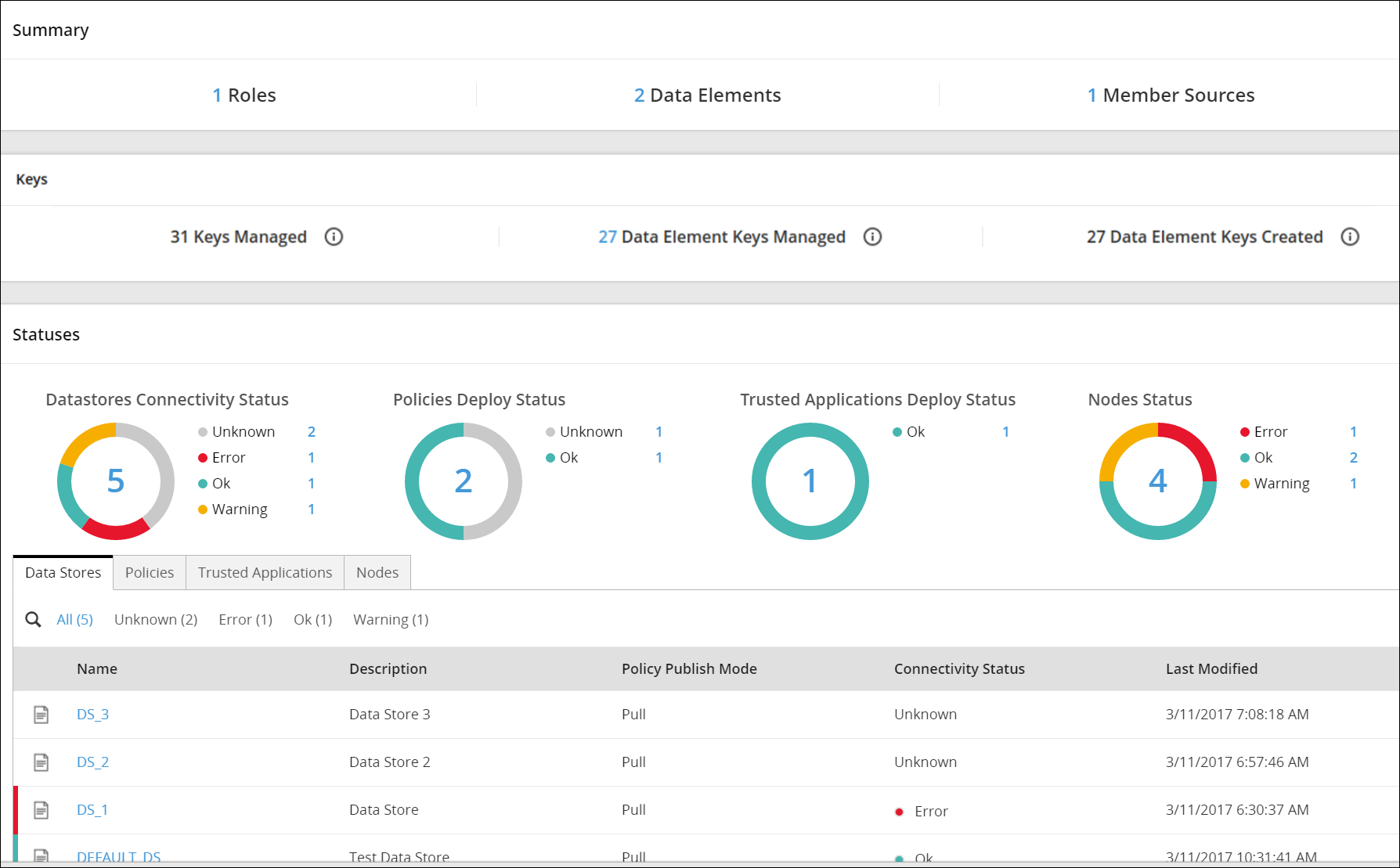
The Policy Management dashboard consists of the following three areas:
- Summary
- Keys
- Statuses - The Statuses area is a legacy feature that is not applicable for 10.0.0 protectors and later.
Summary
This section provides information about the Summary area in the Policy Management dashboard.
The Summary area displays an overview of the number of policy components created using the Policy Management Web UI. The following policy components appear under the Summary area:
- Roles
- Data Elements
- Member Sources
You can navigate to the respective policy components by clicking the corresponding number.
For example, you click 2 corresponding to Data Elements, to view the list of data elements.

Keys
This section provides information about the Keys area in the Policy Management dashboard.
The Keys tab displays an overview on the number of keys managed and created using the Key Management Web UI. The following key components appear under the Keys area:
- Keys Managed: Total number of keys present in the Policy Management system. This includes the Master Keys, Repository Keys, Signing Keys, Data Store Keys, and Data Element Keys. This number also includes all the rotated keys.
- Data Element Keys Managed: Total number of Data Element Keys currently present in the Policy Management system. Each key is connected to an existing Data Element. This number also includes the rotated Data Element Keys. It is important to note that a maximum number of 8191 keys can be present in the system.
- Data Element Keys Created: Total number of Data Element keys that have been ever created in the Policy Management system. This number also includes the keys that you have created earlier but have subsequently removed after deleting a data element. It is important to note that you can create a maximum number of 8191 keys.
The following figure shows the Keys area.

9 - Exporting Package for Resilient Protectors
The export package process includes an API for exporting the package from the ESA. The exported package is used by the resilient protectors.
The following table provides information about each component that must be used or configured to export the package from the ESA.
| Policy Components | Description | Reference |
|---|
| RPS API | After the package is configured on the ESA, the RPS API helps in exporting the package that can be imported to the resilient protectors.
For more information about how resilient packages are imported to protectors, refer to the respective Resilient Protector documentation. | For more information about the RPS API, refer to section APIs for Resilient Protectors in the Protegrity APIs, UDFs, Commands Reference Guide. |
| RPS Service | The RPS service is installed on the ESA. This service must be up and running before any resource is requested using the RPS API. | - Verifying the RPS service - section Verifying the RPS Service for Policy Deployment on Resilient Protectors in the Installation Guide.
- RPS service - section Start and Stop Services in the Appliance Overview Guide. |
| Export Resilient Package permission | The Export Resilient Package permission must be assigned to the role that will be granted to the user exporting the package. | For more information about the permission, refer to Managing Roles in the Appliance Overview Guide. |
10 - Legacy Features
Legacy Policy Management features no longer applicable for 10.0.0 protectors.
The following Policy Management features are not applicable for 10.0.0 protectors and later:
- Policy Management > Nodes
- Policy Management > Dashboard > Statuses
For more information about these Legacy features for your supported Protectors earlier than 10.0.0, refer to a corresponding version of the Policy Management Guide from the My.Protegrity website.
For 10.0.0 protectors and later, you can access the information about the protector nodes and statuses from the Protegrity Dashboard.


