This is the multi-page printable view of this section. Click here to print.
Data Security Gateway (DSG)
- 1: Protegrity Gateway Technology
- 2: Protegrity Gateway Product
- 3: Technical Architecture
- 3.1: Configuration over Programming (CoP) Architecture
- 3.2: Dynamic Configuration over Programming (CoP)
- 4: Deployment Scenarios
- 5: Protegrity Methodology
- 6: Planning for Gateway Installation
- 6.1: LDAP and SSO Configurations
- 6.2: Mapping of Sensitive Data Primitives
- 6.3: Network Planning
- 6.4: HTTP URL Rewriting
- 6.5: Clustering and Load Balancing
- 6.6: SSL Certificates
- 7: Installing the DSG
- 7.1: Installing the DSG On-Premise
- 7.2: Installing DSG on Cloud Installation
- 7.2.1: Installing DSG on AWS
- 7.2.2: Installing DSG on Azure
- 7.2.2.1: Creating Image and VM on Azure
- 7.2.2.2: Adding and Configuring the Second Network Interface
- 7.2.2.3: Finalizing the DSG Installation
- 7.2.2.4: Azure Cloud Utility
- 7.2.3: Installing DSG on GCP
- 7.2.3.1: Creating a VM Instance from an Image
- 7.2.3.2: Finalizing the DSG Installation
- 7.3: Installing the DSG patch on ESA
- 7.4: Configuring the DSG Cluster
- 7.5: Forward Logs to the Audit Store
- 7.6: Registering the DSG node with ESA
- 7.7: Updating the host name or domain name of the DSG or ESA
- 7.8: Updating the host details
- 8: Trusted Appliances Cluster
- 9: Upgrading to DSG 3.3.0.1
- 10: Ascertaining the Host Address in the Server Certificates
- 11: Setting up ESA Communication
- 12: FAQs for DSG
- 13: Web UI
- 13.1: Cluster
- 13.1.1: Monitoring
- 13.1.2: Log Viewer
- 13.2: Ruleset
- 13.2.1: Learn Mode
- 13.2.1.1: Learn Mode Scheduled Task
- 13.2.2: Ruleset Tab
- 13.2.2.1: Ruleset Versioning
- 13.3: Transport
- 13.3.1: Tunnels
- 13.3.1.1: Manage a Tunnel
- 13.3.1.2: Amazon S3 Tunnel
- 13.3.1.3: HTTP Tunnel
- 13.3.1.4: SFTP Tunnel
- 13.3.1.5: SMTP Tunnel
- 13.3.1.6: NFS/CIFS
- 13.3.1.6.1: NFS/CIFS
- 13.3.2: Certificates/Key Material
- 13.3.2.1: Certificates Tab
- 13.3.2.2: Delete Certificates and Keys
- 13.3.2.3: Keys Subtab
- 13.3.2.4: Other Files Subtab
- 13.3.2.5: Upload Certificate/Keys
- 13.4: Global Settings
- 13.4.1: Debug
- 13.4.2: Global Protocol Stack
- 13.4.3: Web UI
- 13.5: Tokenization Portal
- 14: Overview of Sub Clustering
- 15: Implementation
- 16: Transaction Metrics Logging
- 17: Error Metrics Logging
- 18: Usage Metrics Logging
- 19: Ruleset Reference
- 19.1: Services
- 19.1.1: Amazon S3 Out-of-Band Service
- 19.1.2: Mounted File System Out-of-Band Service
- 19.1.3: REST API Service
- 19.1.4: Secure Web socket (WSS)
- 19.1.5: SFTP Gateway Service
- 19.1.6: SMTP Gateway Service
- 19.2: Profiles
- 19.3: Actions
- 19.3.1: Error
- 19.3.2: Exit
- 19.3.3: Extract
- 19.3.3.1: Adobe Action Message Format
- 19.3.3.2: Amazon S3 Object
- 19.3.3.3: Binary Payload
- 19.3.3.4: CSV Payload
- 19.3.3.5: Common Event Format (CEF)
- 19.3.3.6: XML Payload
- 19.3.3.7: Date Time Format
- 19.3.3.8: XML with Tree-of-Trees (ToT)
- 19.3.3.9: Fixed Width
- 19.3.3.10: HTML Form Media Payload
- 19.3.3.11: HTTP Message Payload
- 19.3.3.12: Enhanced Adobe PDF Codec
- 19.3.3.13: JSON Payload
- 19.3.3.14: JSON with Tree-of-Trees (ToT)
- 19.3.3.15: Microsoft Office Documents
- 19.3.3.16: Multipart Mime Payload
- 19.3.3.17: PDF Payload
- 19.3.3.18: Protocol Buffer Payload
- 19.3.3.19: Secure File Transfer Payload
- 19.3.3.20: Shared File
- 19.3.3.21: SMTP Message Payload
- 19.3.3.22: Text Payload
- 19.3.3.23: URL Payload
- 19.3.3.24: User Defined Extraction Payload
- 19.3.3.25: ZIP Compressed File Payload
- 19.3.4: Log
- 19.3.5: Profile Reference
- 19.3.6: Set User Identity
- 19.3.7: Set Context Variable
- 19.3.8: Transform
- 19.3.8.1: GNU Privacy Guard (GPG)
- 19.3.8.2: Protegrity Data Protection Method
- 19.3.8.3: Regular Expression Replace
- 19.3.8.4: Security Assertion Markup Language (SAML) codec
- 19.3.8.5: User Defined Transformation
- 19.3.9: Dynamic Injection
- 20: DSG REST API
- 21: Enabling Selective Tunnel Loading on DSG Nodes
- 22: User Defined Functions (UDFs)
- 23: API for Exporting the CoP
- 24: Best Practices
- 25: Known Limitations
- 26: Migrate UDFs to Python 3
- 27: PEP Server Configuration File
- 28: Additional Configurations in gateway.json File
- 29: Auditing and Logging
- 30: Verifying UDF Rules for Blocked Modules and Methods
- 31: Managing PEP Server Configuration File
- 32: OpenSSL Curve Names, Algorithms, and Options
- 33: Encoding List
- 34: Configuring Default Gateway
- 35: Working with Backup and Restore
- 36: Deploying Configurations to the Cluster
- 37: Restarting a Node
- 38: Deploy Configurations to Node Groups
- 39: Codebook Reshuffling
- 40: Troubleshooting the DSG
1 - Protegrity Gateway Technology
Protegrity Gateway Technology provides an insight into the gateway technology offered that lets you protect data at rest as well as on the fly.
Background
The most important asset for organizations today is data. Data is being collected at an unprecedented rate. Data analysts and data mining scientists develop analytical processes to gain transformative insights from the collected data to gain corporate advantages, growth, and innovation.
This rich pool of data is commonly tied to individuals, such as employees, customers, patients, and the like, making it a target for identity theft. The ever-increasing cases of data breaches is a proof that the business of stealing data is a large and lucrative business for hackers. In effort to stop data thefts, organizations are constantly looking for innovative solutions for protecting sensitive data without affecting the use and analysis of this data.
Audience
Multiple stakeholders collaborate to deliver enterprise level data security solutions. Some are responsible for setting corporate business requirements while others own the responsibility of designing and implementing data security solutions.
The audience for this document is the following stakeholders who play a role in the data security ecosystem:
Business Owners: Focused on maximizing the value and growth delivered by their business system. Data security concerns and security solutions may prevent business owners from executing their plans. These stakeholders are the advocate for the data and its untapped potential.
Security Professionals (CISO, Security Officers, Governance, Risk, etc.): Responsible for keeping business systems secure. They must understand the goals of the business owners and design and deliver data security solutions that offer a balance between protecting the data and enabling business usage. These security professionals:
- Set the security risk tolerance for the organization.
- Identify the data that is deemed sensitive in an organization.
- Design and implement the data security solution that meets business requirements.
- Establish the ongoing monitoring and alerting of sensitive data.
IT (DBA’s, Developers, etc.): Responsible for implementing and deploying business and data security solution. Some organizations have a specialized IT team that is part of the security organization. In this document, this team is identified as the team that implements and deploys the data security solution, irrespective of their location in the organization chart.
System Architects: Equipped with deep knowledge of business infrastructure and of the corporate data security requirements makes them the center authority responsible for the technical architecture of the data security solution.
These stakeholders are involved from the initial stages of vetting data security vendors to the eventual design of the data security architecture implemented by the IT stakeholders.
What is Protegrity Gateway Technology
Protegrity Gateway Technology is an umbrella term for the new and innovative push to deliver data security solutions from Protegrity that is highly transparent to corporate infrastructures.
When adopting data security solutions, companies expect minimal impact on existing business systems and processes. In the past, data security solutions have been integrated into business applications and databases.

These approaches require changes to these systems.
The gateway is a network intermediary between systems that communicate with each other through the network. By delivering data security solutions on the network, changes to the existing systems are avoided or minimized.

The Protegrity Gateway Technology protects data on the network.
Why the Protegrity gateway technology?
The Protegrity Gateway Technology represents an extension to the Protegrity Data-Centric Audit and Protection (DCAP) platform and Protegrity Vaultless Tokenization. The largest enterprises worldwide are using these today to protect sensitive data.
The combination of the Protegrity DCAP platform, Protegrity Vaultless Tokenization, and the Protegrity Gateway Technology delivers many benefits:
Enterprise: As yet another protector in the Protegrity Data Centric Audit and Protection platform family, the Protegrity Gateways can receive and use policies from the Enterprise Security Administrator (ESA), which defines how sensitive data should be protected across the enterprise. The protected data is interoperable with other protectors in the DCAP family.
Transparent: Delivering data protection on the network eliminates the need to modify the source or destination systems. This offers alternative approaches to implementing a security solution, often eliminating the need to modify application code or database schemas.
Fast: The gateway provides the fastest mechanism to protect and unprotect data at line speed. The granularity of the security operations is very high since the operations are applied very close to the data with reduced latency.
Scalability: The gateways can scale vertically as well as horizontally. The vertical scaling is enabled through the addition of CPU and RAM while horizontal scaling is enabled by adding more nodes to a gateway cluster.
Configuration over Programming (CoP): The implementation of data security with the Protegrity Gateways does not require programming. Implementation is configured through an easy to use web interface. This practice is called Configuration over Programming (CoP).
Deployment Flexibility: The Protegrity Gateways as well as the Protegrity DCAP platform can be deployed on-premise, in the cloud deployment, or in a hybrid deployment architecture.
Use Cases: The Protegrity Gateway Technology is a kind of “Swiss Army Knife” for applying data security across many use cases that are described in detail in this document.
Extensibility: While CoP delivers virtually all you need to implement data security solutions using the Protegrity Gateways, you may extend the functionality using Python programming language through User Defined Functions.
SaaS Protection Agility: SaaS applications (Salesforce, Workday, Box, etc.) have gained popularity due to the ease with which you can add business functionality to your organization. Because of their cloud-based deployment model, SaaS applications can change quickly. The approach of implementing data security solutions with Configuration over Programming (CoP) provides the ability to keep up with these changes and avoid outages.
How Protegrity gateway protects data
Protegrity gateways deliver security operations on sensitive data by peering into the payloads that are being transmitted through the network.
The gateway intercepts standard protocols such as TCP/IP. The payloads on the backs of these protocols are scanned for sensitive data and security operations (protection or un-protection) are applied to the sensitive data as it passes through the gateway. With the gateway approach to delivering security operations, impact to existing systems is eliminated or minimized.

Data-centric auditing and protection platform
Protegrity Gateway Technology is part of the Protegrity Data-Centric Audit and Protection family of protectors. Protegrity Gateway Technology together with the Enterprise Security Administrator (ESA) makes up the Protegrity Data-Centric Audit and Protection Platform.

The Enterprise Security Administrator (ESA) is a central point of management of data security policies enforced by various protectors. Each protector is designed to accept an ESA policy that provide the rules for protecting and unprotecting sensitive data.
Security operations on sensitive data performed by any of the protectors can be audited. Audit logs based on invoked security operations are sent back to ESA for reporting and alerting purposes.
You can protect sensitive data in any business system that is secured with Protegrity. It allows the protected data to travel in a protected state between different business systems, and then unprotect it in a target system for authorized users.
Fine Grained and Coarse Grained Data Security:
Data security encompasses various types of security, which are distinguished based on the point at which security policies are applied. For example, security implemented at the network level can restrict access to systems containing sensitive data.
Security applied to data can be delivered in the following forms:
It can be applied to the data as an access control layer by hiding data from un-authorized users.
It can be applied to data by encrypting the raw storage associated with data stores. This is sometimes called coarse grained data protection or tablespace protection or Transparent Database Encryption.
It can also be applied to the specific data itself with encryption or tokenization such as the Social Security Number, the E-mail address, the Name and so on.
Protegrity Vaultless Tokenization enables you to reduce the scope of systems where sensitive data exists in the clear, with minimum to no impact of its business usage.
Together with other protectors contained in the Protegrity Data-Centric Audit and Protection platform, the Protegrity Gateway Technology products deliver on these approaches with a single product.
Configuration over Programming (CoP) brings it all together
The Protegrity Gateway Technology brings together the ability to peer into network payloads and the security policy-based rules for protecting sensitive data with a concept called Configuration over Programming (CoP).

The diagram above depicts the gateway along with the components that together constitute CoP. Data is transmitted bidirectional between System A and System B. The gateway acts as a network intermediary through which the transmissions pass. A set of rules called CoP Profiles define the transformations performed on that data.
Security Officers set rules that define how the security team would like corporate security solutions to treat sensitive data. Having the security team define these rules across the corporate data asset delivers consistency in the security treatment. This helps both security and the usability of the data. Having the security team responsible for this task also delivers separation of duties. This helps to reduce or eliminate a conflict of interest in who sets the rules for protecting sensitive data and who can see the sensitive data in the clear.
IT technical resources bring it all together through CoP. CoP enables a technical resource, a CoP Administrator, to create a set of CoP profiles that blend the different aspects of delivering security or other transformations on data. A CoP Profile include:
Data Collection: The data collection profile rules define the network protocols that are being inspected. For example, you can instruct the gateway that it will inspect HTTP or SFTP. These are standard protocols on top of which the transmission of data across networks are built.
Extend Gateway: If you have a custom protocol, the gateway can be extended and configured to accept that as well.
Data Extraction: Protocols carry many kinds of payloads that are commonly used. They carry web pages or document content that are used to transfer business system data from one application to another. CoP Profiles are configured to identify specific data within these commonly used payloads.
Extend Codecs: A set of extraction codecs are included with the gateway. As with the protocols, the data extraction codecs can also be extended to include new standard or custom codecs.
Actions on Data: Once you have defined the protocol and identified specific data within a payload, you can then apply an action or a transformation rule on the data. In the context to data security, this action is a security operation (protect or unprotect). The rules for performing the security action come from the policy rules identified by the security team.
2 - Protegrity Gateway Product
The Protegrity Gateway Technology applies security operations on the network. The Data Security Gateway (DSG) offers flexibility and can run in the following environments:
- On-premise: Appliance runs on dedicated hardware.
- Virtualized: The appliance runs on a virtual machine.
- Cloud: The appliance runs on or is as part of a Cloud-based service.
- Containers: DSG is deployed as a containerized application.
SaaS based business applications are being adopted at a rapid pace. Organizations use SaaS-based applications to fulfill different business needs. For example, SaaS based CRM applications can be used to manage their customer relationship. Company’s purchasing SaaS applications are outsourcing the burden of development, maintenance, and infrastructure to the SaaS vendors. A subscription contract and a browser are all that is required.
These SaaS applications store corporate data in the cloud, some of which may be sensitive. The DSG can be used to protect sensitive data as it moves from a corporate environment to the SaaS application storage. When the data is returned, the sensitive protected data is unprotected according to the Protegrity Security Policy and delivered to the intended user in a usable form.

CoP Profiles are available for certain SaaS applications. Also, profiles can be created to configure the DSG to protect and unprotect sensitive data for a specific SaaS application. The DSG delivers differentiation from other vendors described in the following points:
Security: DSG protects sensitive data that is stored in the SaaS cloud storage. This data is rendered in an unusable form to system administrators who maintain the SaaS application. If security imposed by the SaaS application is breached, the data still stays protected. Cryptographic keys used to protect and unprotect sensitive data are stored on-premise. This gives control over the sensitive data.
This platform can be used for Data Residency Applications that have been recently highlighted by the changes in the European safe harbor requirements.
Enterprise data security: CoP profiles use the data security policy rules to control how sensitive data is protected throughout an organization. These rules are created in ESA by the security professionals. Data protected in the SaaS and that moves between business systems realize the benefit of a consistent enterprise data security model. Secured data is interoperable between business systems. Data is then secured at rest and in transit.
Agility: SaaS applications are built on a SaaS model. This model allows SaaS to add functionality with minimal effort of installing new software or other complexities. A new feature is developed and made available the next time a user loads the application on their browser. Thus, the applications are subject to change.
Data security solutions that protect SaaS applications must be agile in reacting to these changes. Certain SaaS data security vendors require building new products to accommodate these changes in their security solution. The DSG uses the Configuration over Programming (CoP) to manage these changes. The CoP model uses profiles, that require little to no programming, to configure the changes.
SaaS change monitoring: Companies subscribe to SaaS applications as it readily lets them add business functionality to their business. These SaaS applications are subject to change. These changes should not break the security solution. These changes will be identified and CoP Profile configuration modifications will be provided to secure and run a business.
Third-party integration: Often, SaaS applications will communicate with other SaaS applications and business processes through RESTful APIs. DSG can be used to perform security operations between these systems. For example, data in a SaaS application like Salesforce may require protection. When data is pulled from the Salesforce into other third party application, the data may be in the clear. DSG can intercept these APIs and unprotect data that needs to be used in the third-party business process.
The DSG applies data security operations on the network and uses the CoP Profiles to configure a data security solution.
When building modern business applications, browsers are the primary means of interaction between users and the business system. Network based protocols, such as web services or RESTful APIs, form the way of communicating with business functions or systems.
Flexibility: DSG can be applied to several use cases that are outside the realm of SaaS applications. This “Swiss Army Knife” type of product can single-handedly account for different data security scenarios. These scenarios together will constitute a holistic and complete solution. This is a powerful addition to the development set of tools.
Transparency: By applying security operations on the network, DSG reduces the amount of work required to protect the organization.
Enterprise: Data protection with DSG can be combined with any other protector in the Protegrity Security platform. If the gateway does not meet a specific requirement, data security solutions can be accomplished with other protectors in the platform.
The set of security scenarios described in the following section gives a glimpse of the flexibility of this product.
DSG used to protect web applications
Most applications today are based on a web interface. Web interfaces have an architecture that protect data from the browser to the Web Server with HTTPS. The Web Server terminates HTTPS and the traffic flows through Application Servers. Finally, the traffic flows into a data store. Sometimes there are business systems that process data from the databases.

From a security point of view, the data that is flowing after HTTPS is terminated will be in the clear. Adding a DSG before the Web Server can terminate HTTPS and execute the CoP Profile to extract and protect any sensitive data. For example, if an SSN is entered in a web form, a specific CoP Profile rule can be created. This rule picks out the HTML label associated with the value entered and protects the SSN.
Like Web Servers and App Servers, the DSGs are stateless and can be placed behind a load balancer. Vertical and horizontal scaling can manage the throughput required to maintain business performance.
Consider the following cases:
- Business functions are performed in the App Server on sensitive data.
- Business functions are performed in the database itself within stored procedures.
In such cases, DSG provides a RESTful API Server. Database UDFs from Protegrity Database Protectors can also be used.
Data security gateway as an API security gateway
APIs are the interoperability language of modern architectures. Classic use of APIs are for interfaces internal to applications. Also, APIs move data and execute processes between disparity applications.

These APIs are implemented in the form of SOAP based Web Services or RESTful APIs. In these scenarios, techniques to implement both the client and the server component can be used. The server component may also come from different vendors.
Irrespective of how this architecture is implemented, the DSG can be placed between the client and the server. Here, a CoP Profile can be used to specify what and how sensitive data passing in either direction will be protected or un-protected.
DSG for files
A common scenario found in enterprises today is the delivery of files into an organization from business partners. Often, the security approach to protecting data in transit from the source to the destination is SFTP.

However, when the file lands in the SFTP Server, the encryption is terminated and the sensitive fields in the clear. This is similar to the web application scenario for the HTTPS server. The data downstream is exposed in the clear.
The DSG can be placed between the SFTP client and the SFTP Server. It terminates the network security making the payload visible to the gateway. A CoP Profile is then created to perform diverse types of security operations to the file.
Coarse Grained Protection: CoP Profile rules can be created to encrypt the entire file before it lands on the SFTP Server.
Fine Grained Protection: CoP Profile rules can be created to encrypt or tokenize specific sensitive data contained within the file.
DSG as an on-demand RESTful API server
RESTful APIs can be used to perform certain functions that are delivered by the REST Server. In context to data security, business applications can make requests to the DSG as a RESTful Server for data protection.

Protecting or unprotecting data is easy. Send the document that contains the data to be acted on and the CoP Profile rules take care of the rest. The rule will identify the exact part of the document and act on that data. There is no need to parse that data out and then reconstruct the document after the security operation is performed.
3 - Technical Architecture
System architecture
Protegrity Gateway Technology products are assembled on a layered architecture. The lower layers provide the foundational aspects of the system such as clustering and protocol stacks. The higher layers are specialized and provide various business functions. They are building blocks that instruct on how the gateway should act on data. Some of these building blocks include functions such as decoders for various data formats as well as data transformation for cryptography.
The gateway architecture provides standard out-of-the-box building blocks. These building blocks can be extended by the customer at each layer as per their requirements. These requirements can be security-related or requirements that will aid the customer in processing data.
The following figure shows a view of the gateway system architecture.

Platform
The Platform Layer runs on top of customer-provided hardware or virtualization resources. It includes an operating system that has been security-hardened by Protegrity, along with an infrastructure layer above it known as the Protegrity Appliance Framework.
The Protegrity Appliance Framework is responsible for common services, such as inter-node communications mechanisms and clustering. Data communicated through the platform layer is passed onto the Data Collection Layer for further processing.
Data collection
The Data Collection Layer is the glue between the higher layers of the gateway and the external world. It is responsible for ingesting data into the gateway and passing it on higher layers for further processing. Likewise, it is responsible for receiving data from the higher layers and outputting it to the external world. In the TCP/IP architecture terms, this is the transport/application protocol layer of the gateway architecture.
Since the primary method by which the gateway interfaces with the external world is through networking, data is typically transmitted to and from the gateway using application-layer protocols such as HTTP, SFTP, and SMTP. The gateway terminates these protocol stacks. These protocols can be extended to include any custom protocol developed by a company to meet its specific requirements, using the gateway’s built-in User Defined Function (UDF) service.
Data delivered through these protocols are passed to the Data Extraction Layer for further processing.
Data extraction layer
The Data Extraction Layer is at the heart of fine-grained data inspection capabilities of the gateway. The Data Extraction layer is split into two logical functions:
Codecs: These are the parsers or the data encoders/decoders targeted at following individual native formats, such as XML, JSON, PDF, ZIP, and Open-Office file formats such as DOCX, PPTX, and XLSX.
Extractors: These are responsible for fine-grained extraction of selected data from within the larger data sets produced by the codec components. These include mechanisms such as Regular Expressions, XPath, and JSONPath.
The subsets of data extracted by the Data Extraction Layer are passed up to the Action Layer. Here, they may be transformed for data security or acted upon for some other business logic. Transformed data subsets received from the Action Layer are substituted in their original place in the original payload. The modified payload is encoded and delivered down to the Data Collection layer for outputting to the external world.
The building blocks in this layer can be extended to include custom requirements through UDFs. UDFs enables customers to build and extend the gateway with their own data decoding and extraction logic using the Python programing language.
Data extracted from payloads is passed to the Action Layer for further processing.
Action layer
The Action Layer is responsible for operating on the data passed on to it by the Data Extraction Layer. The data extracted is processed by actions in the Action Layer.
Operating on this data may include transforming the data for security purposes. This includes all the data security capabilities provided by the core Protegrity platform, such as encryption, tokenization, unprotection, re-protection, hashing, and masking.
This layer also includes a UDF component, enables customers to extend the system with their own action transformation logic using the Python programming language.
3.1 - Configuration over Programming (CoP) Architecture
CoP overview
CoP is a key paradigm used in the Protegrity Gateway Technology. The CoP technology enables a CoP administrator to create a set of rules that instructs the gateway on how to process data that traverses it.
The CoP technology is also a key component from a user experience perspective. The hierarchical structure of the rules is just as important as the rules themselves. The set of rules, their structure, and an easy-to-use interface results in a powerful toolset called the CoP.
The DSG is fundamentally architected on the CoP principle. CoP suggests that configuration should be the preferred way of extending or customizing a system as opposed to programming. Users configure rules in a Web UI to define step-by-step processing of incoming messages. This allows DSG users to handle any type of input message such as CSV, fixed-width, or plain text as long as corresponding rules exist within the DSG. The rules are generally categorized as extraction, such as message parsing, and transformation, such as data protection.
The DSG product evolution started with Static CoP, where the request processing rules are configured ahead of time. However, the DSG now incorporates Dynamic CoP, allowing JSON-structured rule definitions to be dynamically injected into request messages, such as an HTTP header field, and executed on the fly.

DSG users configure the CoP Rulesets to construct a REST API that is suitable to their environment. The DSG’s RESTful interface operates at a sufficiently high level that API users are not exposed to low-level cryptographic API message sequences, such as open and close session. Low-level parameters such as data element names, session handles, and similar details are not exposed either. User identity can either be pre-configured in the DSG, derived as a result of HTTP Basic Authentication, or dynamically provided through the API as an HTTP header, whose name is user configurable, or as part of the HTTP message body.
The following figure shows high-level functionality of the DSG RESTful interface.

For simplicity, the DSG example above uses a plain text string that is tokenized word by word, with protected tokens returned in the 200 OK response. The DSG includes a wide range of codecs, which are message parsers that enable it to interpret and process complex payload bodies. DSG’s codecs include XML, JSON, Text, Binary, CSV, Fixed Width, MS Office, PDF, Google Protocol Buffers, HPE ArcSight CEF, Date-Time, and PGP. The DSG also allows custom extraction and transformation rules to be written in Python and integrated into the CoP Rulesets.
The following sections describe the DSG Rulesets, their Structure and the Ruleset engine followed by an example.
CoP Ruleset
The DSG contains built-in standard protocol codecs that enable configuration-driven payload parsing and processing for most data security use cases encountered in typical networking protocols.
The Ruleset describes a set of instructions that the gateway uses to transform data as it traverses the gateway in any direction. The various kinds of Rule objects currently available in the gateway are illustrated in the following figure.

A typical Ruleset is constructed from the Extract and Transform rules.
The core rules available today are:
Extract: Extraction rules are responsible for extracting subsets of data from larger bodies of data. By way of engaging existing codecs, they are also capable of interpreting data per predefined encoding schemes. While the Extraction rules function as data filters, they do not actually manipulate data. Therefore, they are branch nodes in the Ruleset tree and have child rules below them.
Transform: Transformation rules are responsible for manipulating data passed into them. Typical data security use cases will employ pre-packaged Transformation rules for performing data protection, un-protection, re-protection, masking, or hashing.
Customers can extend the out-of-the-box transformations with custom Python-coded Transformation User-Defined Functions (UDFs) when the built-in security actions are insufficient.
Log: The Log rule object allows log entries to be added to the DSG log. The user can define the level of logging to be reflected in the log, such as Warning, Error, and so on.
Exit: The Exit option acts as a terminating action and the rules are not processed further.
Set User identity: The Set User Identity rule object comes in effect if username details are part of the payload. The Protegrity Data Protection transformation leverages the value set in this rule such that the subsequent transformation action calls are performed by the set user.
Profile Reference: An external profile can be referenced using the Profile Reference action. This rule transfers the control to a separate batch of rules grouped in a profile.
Error: Use this action to add a custom response message for any invalid content.
Dynamic Injection: Use Dynamic CoP to send rules for extraction and transformation as part of a request header along with the data for protection in the request message body.
Set Context Variable: Use this action type when you want to pass a value as input to the rule. The value set within this rule will be maintained throughout the rule’s lifecycle.
Ruleset Structure
Rulesets are organized in a hierarchical structure where Extract rules are branch nodes and other rules such as Transform rules are leaf nodes. In other words, extract specific data from the payload and then perform a Transform action on the data extracted.

Rules are compartmentalized into Profile containers. Profile containers can be enabled or disabled and they can also be referenced by a Profile Reference rule.
Ruleset Tree of Trees (ToT)
Typical rulesets are recursively processed in sequence. With this mechanism, sibling rules under a given parent, along with all child rules belonging to each sibling, are also recursively executed in order. This occurs from top to bottom with no provision for conditional branching.
However, this disallows decision-based, mutually exclusive execution of individual child rules on various parts of extracted data within the same extraction context. Examples include a row in a CSV file, groups within a regular expression, or multiple XPaths within an XML document. This leads to extraction or parsing of the same data multiple times. Various parts of extracted data within the same extraction context may require to be processed differently.
The RuleSet Tree of Trees (ToT) feature is an enhancement to the RuleSet algorithm that addresses this drawback. With the RuleSet ToT feature, an extraction parent rule can have multiple child rules that can be executed mutually-exclusive to each other based on some condition applied in the parent rule. The feature allows different parts of extracted data to be processed downstream using different profile references. Since the profile references are sub-trees in and of themselves, this feature adds a Tree-of-Trees structural notation to the CoP RuleSets.
The following compares the layout and execution paths of traditional rulesets with the ToT rulesets:

In the above example, a CSV payload needs to be processed as per the following requirements:
- Column 1 needs to be protected using an Alphanumeric data element.
- Column 6 needs to be protected using a Date data element.
- Column 9 needs to be protected using a Unicode data element.
The traditional RuleSet strategy involved extracting or parsing the same CSV payload three times, once for each column requiring protection using different data elements, as illustrated on the left side. In contrast, a ToT-enabled RuleSet requires extracting the CSV payload only once where values extracted from different columns can be sent down different child rules that provide different protection data elements. Consequently, the overall CSV payload processing time reduces substantially.
In this release, the Ruleset ToT feature supports the payloads:
Ruleset execution engine
Rulesets are executed with the Ruleset engine that is built into the gateway. The Ruleset engine is responsible for cascaded execution of the Ruleset. The behaviors of Rules objects range from data processing such as Extract and Transform, to controlling the execution flow of the rule tree such as Exit, to supplementary activities such as logging like Log.
The Ruleset engine will recursively traverse the Ruleset node by node. For example, Extract nodes will extract data that will be transformed with a Transform rule node. Following this, the recursion stack is rolled up and the reverse process happens. Here, data is encoded and packaged back to its original format and sent to the intended recipient.
Ruleset and ruleset execution example
In the following example of a Ruleset, the Ruleset structure and the Ruleset execution are illustrated. This example is started with an HTTP POST with an XML payload of a person’s information. The Ruleset is a hierarchy of 3 Extract nodes with the Transform rule as the end leaf node.

Extract Rule: The Extract Rule extracts the XML document from the message body.
Extract Rule: A second Extract Rule will take the XML document and parse the data that is to be transformed – the person’s name. This is done by using XPath.
Extract Rule: A third Extract Rule will split out the name into individual words – in this example, the first and the last name. This is accomplished using REGEX.
Transform Rule: The Transform Rule will take each word and apply an action. In this example the first name is protected and the last name is protected.
The next set of rules will perform operations in the reverse and prepare the contents to go back to the sender. The same Extraction rules would perform reverse processing as the recursion unwinds.
Extract Rule: On the return trip, an Extract Rule is used to combine the protected first and last name into a single string – Name.
Extract Rule: This rule will place the Name back into the XML document.
Extract Rule: The final Extract rule will place the XML document back into the message body to be sent back to the sender with the name protected.
3.2 - Dynamic Configuration over Programming (CoP)
Ruleset execution can be segregated into Static CoP and Dynamic CoP. When the payload type and structure are predictable and known at system configuration time, you can define Rulesets for such payloads and process the data using Static CoP. It is assumed in Static CoP that a user who defines Rulesets is authorized and holds permission to access DSG nodes.
When organizations are divided into disparate systems or applications, and each system user needs to send custom payloads on the fly to DSG nodes with minimal predictability, granting users access to DSG nodes to define Rulesets becomes risky. In such situations, you can use Dynamic CoP to send extraction and transformation rules in the request header, along with the data to be protected in the request message body.
While creating Rulesets for Dynamic CoP, use the Profile Reference rule for data transformation instead of the Transform rule. The security benefits of using Profile Reference rule are higher than the Transform rule. The reason is that the requests can be triggered out of the secure network perimeter of an organization.
Dynamic CoP provides the following advantages:
- Flexibility to send custom requests based on the payload at hand without prior customization to Ruleset configuration
- Restrict or configure the allowed actions that users can send in the request header.
The following figure illustrates how Static CoP RuleSets are combined with Dynamic CoP Rulesets as part of a given REST API or Gateway transaction:

- The Static CoP Administrator creates the tunnel configurations and Ruleset for the Static CoP rule execution. This static rule forms the base for the Dynamic rule to follow. Based on the URI defined in both the Static CoP rule and Dynamic CoP rule, the entire Ruleset structure is executed when a request is received.
- The REST API or gateway clients can be application developers of multiple applications in an organization who need to protect their data on the fly.
- The Dynamic CoP structure provides an outline of how the request header must be constructed.
- When the request is sent, the header hooks to the Dynamic Injection action type that is part of the Ruleset structure. The Ruleset executes successfully and protected data is sent as a response.
Dynamic CoP structure
Based on the type of Ruleset execution to be achieved, Dynamic CoP can either be implemented with ToT or without ToT.
The following structure explains Ruleset structure when Dynamic CoP is implemented without ToT.

The following structure explains Ruleset structure when Dynamic CoP is implemented with ToT.

In the Figure, the profileName is the profile reference to the profile that the ToT structure follows. Ensure that you understand the Ruleset structure/hierarchy at the DSG node before configuring the Dynamic CoP with ToT rule. Refer to Dynamic rule and Dynamic rule injection.
Use case implemented using Static CoP
The following image explains how the use case would be implemented if static CoP is used.

The individual steps are described as following.
Step 1 – This step extracts the body of the HTTP request message. The extracted body content will be the entire JSON document in our example. The extracted output of this Rule will be fed to all its children sequentially. In this example, there is only one child of this extraction rule which is step 2.
Step 2 – This step parses the JSON input as a text document. This is done such that a regular expression can be evaluated to find sensitive data in the document. This step will yield person name strings “Joe Smith” and “Alice Miller” to this child rule. In this example, there is only one child of this extraction rule which is step 3.
Step 3 – This step splits the extracted data from the previous rule into words. Step number 2 above yielded all person names in the document as strings and this rule in step 3 will split those strings into names . The names can then be protected word by word. This will be done by running a simple REGEX on the input. Each word “Joe”, “Smith”, “Alice”, will be fed into children rule nodes of this rule one by one. In this example, there is only one child to this rule, which is step 4.
Step 4– This step does the actual data protection. Since this rule is a transformation node - a leaf node without any children - the rule will return resulting ciphertext or token to the parent.
At the end of Step 4, the RuleSet recursion stack will unwind. Each branch Rule node will reverse its previous action such that the overall data can be returned to its original format. Going back in the reverse direction, Step 4 will return tokens to Step 3 which will concatenate them together into a string. Step 2 will substitute the strings yielded from Step 3 into the original JSON document in place of the original plaintext strings. Step 1 that was responsible for extracting the body of the HTTP request will replace what has been extracted with the modified JSON document. A layer of platform logic outside the RuleSet tree execution will create an HTTP response message. This message will convey the modified JSON document back to the client.
Use case implemented using Dynamic CoP
The following image explains how the use case would be implemented if dynamic CoP is used.

Among the 4 steps described in implementing Static CoP, steps 2 and 3 are the ones that dictate the real business logic that may change on a request-by-request basis. Step 1 defines extraction of HTTP request message body, which is standard in any REST API request processing. Step 2 defines how sensitive data is extracted from an input JSON message. Step 3 defines how a string is split into words for word-by-word protection. Step 4 defines the data protection parameters.
The logic for step 4 can either be injected through Dynamic CoP or used through Static CoP using the profile references. The protection rule is statically configured in the system and can be referenced from step 3’s Dynamic CoP JSON rule. Users may choose to use statically configured protection rules. Profile references can be used for an added layer of security controls and governance.
In the example, step 4’s logic will be injected through Dynamic CoP. It shows how to convey data element name and policy user’s identity through Dynamic CoP.
Dynamic CoP Ruleset Configurations
The Dynamic CoP JSON uses the same JSON structure as the Static CoP JSON. The only difference is that Dynamic CoP JSON is dynamically injected. To start off with our Dynamic CoP JSON, parts of the corresponding Static CoP JSON have been copied. You can create the Dynamic CoP JSON programmatically or use canned JSON template strings and substitute the variable values in it on a request-by-request basis.
The RuleSet JSON fragment for steps 2, 3 and 4 is shown in the following figure. This JSON will be delivered as-is in an HTTP header. It is configured as “X-Protegrity-DCoP-Rules” in our example. The DSG will extract this configured header name and inject its value while executing the RuleSet tree.

The following figure shows the skeletal Static CoP RuleSet configuration in ESA WebUI for enabling Dynamic CoP.
")
The following figure shows how the Dynamic CoP rules are conveyed to DSG in an HTTP header field and the JSON response output in the Postman tool.

The JSON response output is the same in both our Static and Dynamic CoP examples.
4 - Deployment Scenarios
The Protegrity Gateway Technology has the flexibility to be deployed in any of the following environments:
- On-premise.
- Private cloud.
- Public cloud.
- Hybrid combinations if the necessary network communication is available to its consumers.
The deployment approach is based on the business and security requirements for your use cases and organization. For example, data security may require an on-premise deployment. This might be necessary to keep the key material within physical geography or corporate logical borders. These borders mark the security perimeter that unprotected sensitive data should not cross.
Security domain borders may also be subject to the type of sensitive data. Functioning as a demarcation point, the gateway can protect and unprotect sensitive data crossing these borders. A business data security team will require the gateway to be deployed within their secured domain for the subject sensitive data.
The following diagrams depict different deployment scenarios.

When protecting SaaS Applications, DSG is deployed on-premise of the company that is using the SaaS application as a business system.

When protecting Web Applications that are deployed on-premise, the DSG is deployed on-premise of the company that is hosting the web application infrastructure.

Companies have the option of deploying the DSG on the private or public cloud environment.
5 - Protegrity Methodology
The Protegrity Methodology helps organizations implement a data security solution through a set of steps that start with data governance and ends at rolling out the implemented solution.
Data governance
Corporate Data Governance, often based on a board level directive, will specify the data that is sensitive to an organization. The source of these data elements may come from regulatory requirements or from internal corporate security goals that go beyond standard compliance. These are the data elements that will be the focus of designing and delivering a data security solution.
Discovery
During the Discovery step, Protegrity Solution Architects will collaborate with the customer corporate IT and Corporate Security stakeholders. They will identify the location and use of the sensitive data that has been identified by Data Governance.
A Discovery document is created that contains the data flows, technologies used (databases, applications, etc.), performance, SLA requirements, and who is authorized to view protected sensitive data in the clear.
Solution design
Based on the results of the Discovery Step, Solution Architects will work with the customer Architecture stakeholders to design and document a data security solution. This solution will meet the requirements of Data Governance.
This step involves methodically tracing through the Discover document, following the path of sensitive data as it flows through different technologies. The goal is to deliver end to end data security from the point of entry or creation through business processes, and ultimately until the data is archived or deleted.
At different points during this step, prototyping may be used to assess the impact of a solution over another. The data security solution is recorded in a Solution Design document.
Protegrity Data Security Solutions have the goal of delivering security to match the risk tolerance of the organization while recognizing the trade-off between security and usability.
Product installation
The Solution Design document will identify the list of Protegrity products that will be used to satisfy the customer data security requirements. These products need to be installed on the target environments.
The installation step also involves basic settings and verification of connectivity among the designed solution product components.
Solution configuration
The Protegrity platform has the flexibility to protect whatever data your organization deems sensitive and to use the most appropriate protection method. Configuring the solution means that data security policies will be created and deployed to the Protegrity protectors. The policies will identify the data that needs to be protected, how that data is to be protected and who should have access to that data. These policies are deployed to all Protegrity protection agents and will guide protectors on all data security operations.
In addition to the data security policy, the protectors are configured to bind the data protection operations to a target layer, system or environment. The Data Security Gateway (DSG) is integrated at the network level, therefore it is likely that the configuration step will also involve network firewall, load balancer, and IDP configuration or integration. Specific Gateway Rulesets for the designed solution will also be identified and set as part of this step.
Initial migration
With all data security solutions where sensitive data is being protected, existing data must also be secured through a process known as Initial Migration. This step protects all the sensitive data that pre-exists in the system in an unprotected state.
Testing
Data Security Solutions add security functions that will protect and unprotect sensitive data. These security operations may be constrained to certain individuals or processes. The step in the Protegrity Methodology will require the testing of the data security solution before rolling the solution out.
The focus of this methodology step is to ensure that the data is protected, when it should be protected, when it should be unprotected, and that business systems continue to operate normally under the control of the data security policy.
Production rollout
The final step is to roll the solution out and make it available for users.
6 - Planning for Gateway Installation
This section provides information about prerequisites that must be met before the DSG installation can be started.
Planning Overview
This section can be used as a guide and a checklist for what needs to be considered before the DSG is installed.
This document has many examples of technical concepts and activities like the ones described in this section that are part of using and configuring the DSG. As a way of facilitating the explanation of these concepts and activities, a fictitious organization called Biloxi Corp is used. The Biloxi Corp has purchased a SaaS called ffcrm.com. The Protegrity DSG is used to protect Biloxi data that is stored in ffcrm.com.
Minimum Hardware Requirements
The performance of the DSG nodes is primarily dependent on the capabilities of the hardware they are installed on. While optimal hardware server specifications are dependent on individual product usage, the minimum hardware specifications recommended for production environments are as follows:
- CPU: 4 Cores
- Disk Size: 320 GB
- RAM: 16 GB
- Network Interfaces: 2
Note: The hardware configuration required might vary based on the actual usage or amount of data and logs expected.
The Protegrity DSG are certified on the following server platforms.

ESA
The Protegrity DSG is a protector that provides the ability to be centrally managed and controlled from the ESA. As with all Protegrity protectors, a prerequisite to the DSG installation isa working instance of the ESA is required.
Note: For information about the ESA version supported by this release of the DSG, refer to the Data Security Gateway v3.2.0.0 Release Notes.
ESA is the centrally managed component that consists of the policy related data, data store, key material, and the DSG configurations, such as, Certificates, Rulesets, Tunnels, Global Settings, and some additional configurations in the gateway.json file. As per design, the ESA is responsible for pushing the DSG configuration to all the DSG nodes in a cluster.
If you create any configuration on a DSG node and the deploy operation is performed on the ESA, then the configuration on the DSG node will be overwritten by the configuration on the ESA and you will lose all the configuration on the DSG node. Thus, it is recommended that if you are creating any DSG configuration, you must create it on the ESA as the same configurations will be pushed to all the DSG nodes in the cluster. This ensures that the configurations available on all the DSG nodes in a cluster are the same.
Ensure that you push the DSG configurations by clicking Deploy or Deploy to Node Groups from the ESA Web UI. You can click the Deploy or Deploy to Node Groups options from the Cluster and Ruleset screens on the ESA Web UI. Clicking the Deploy or Deploy to Node Groups options from either of these screens on the ESA Web UI ensures that all the DSG configurations are pushed from the ESA to the DSG nodes in a cluster.
Forwarding Logs in DSG
The log management mechanism for Protegrity products forwards the logs to the Audit Store on the ESA.
The following services forwards the logs to the Audit Store:
- td-agent : It forwards the appliance logs to the Audit Store on the ESA.
- Log Forwarder: It forwards the data security operations-related logs, such as, protect, unprotect, and reprotect and the PEP server logs to the Audit Store on the ESA.
Ensure that the Analytics is initialized on the ESA. The initialization of Analytics is required for displaying the Audit Store information on the Audit Store Dashboards. Refer to Initializing analytics on the ESA for initializing Analytics. For more information about configuring the DSG to forward appliance logs to the ESA, refer to Forwarding Logs to Audit Store.
6.1 - LDAP and SSO Configurations
The DSG is dependent on the ESA for user management. The users that are part of an organization AD are configured with the ESA internal LDAP.
If your organization plans to implement SSO authentication across all the Protegrity appliances, then you must enable SSO on the ESA and the DSG. The DSG depends on the ESA for user and access management and it is recommended that user management is performed on the ESA.
Before you can configure SSO with the DSG, you must complete the prerequisites on the ESA.
After completing the prerequisites, ensure that the following order of SSO configuration steps on the DSG nodes are followed.
- Enable SSO on the DSG node.
- Configure the Web browser to add the site to trusted sites.
- Login to the DSG appliance.
Enabling SSO on DSG
This section provides information about enabling SSO on the DSG nodes. It involves setting the ESA FQDN and enabling the SSO option.
Before SSO is enabled, ensure that the following prerequisite is completed.
- Ensure that the ESA FQDN is available.
To enable SSO on the DSG node:
Login to the DSG Web UI.
Navigate to Settings > Users.
Click the Advanced tab.

In the Authentication Server field, enter the ESA FQDN.
Click Update to save the server details.
Click the Enable toggle switch to enable the Kerberos SSO.
Repeat the step 1 to step 6 on all the DSG nodes in the cluster.
Configuring SPNEGO Authentication on the Web Browser
Before implementing Kerberos SSO for Protegrity appliances, you must ensure that the Web browsers are configured to perform SPNEGO authentication. The tasks in this section describe the configurations that must be performed on the Web Browsers. The recommended Web browsers and their versions are as follows:
- Google Chrome version 84.0.4147.135 (64-bit)
- Mozilla Firefox version 79.0 (64-bit) or higher
- Microsoft Edge version 84.0.522.63 (64-bit)
The following sections describe the configurations on the Web browsers.
Configuring SPNEGO Authentication on Firefox
The following steps describe the configurations on Mozilla Firefox.
To configure on the Firefox Web browser:
Open Firefox on the system.
Enter about:config in the URL.
Type negotiate in the Search bar.
Double click on network.negotiate-auth.trusted-uris parameter.
Enter the FQDN of the appliance and exit the browser.
Configuring SPNEGO Authentication on Internet Explorer
The following steps describe the configurations on Internet Explorer 11.
To configure on the Internet Explorer Web browser:
Open Internet Explorer on the machine
Navigate to Tools > Internet options > Security .
Select Local intranet.
Enter the FQDN of the appliance under sites that are included in the local intranet zone.
Select Ok.
Configuring SPNEGO Authentication on Chrome
With Google Chrome, you must set the white list servers that Chrome will negotiate with. If you are using a Windows machine to log in to the appliances, then the configurations entered in other browsers are shared with Chrome. You need not add a separate configuration.
Logging on to the Appliance
After configuring the required SSO settings, you can login to the DSG using SSO.
To login to the DSG using SSO:
Open the Web browser and enter the FQDN of the DSG in the URL.
The following screen appears.

Click Sign in with SAML SSO or Sign in with Kerberos SSO or Sign in .
The Dashboard of the DSG appliance appears.
6.2 - Mapping of Sensitive Data Primitives
Corporate Governance will typically identify the data that is deemed sensitive to an organization. An example of this data can be PCI DSS data such as credit cards, Personally Identifiable Data (PII) and Protected Health Information (PHI). PII can include data elements such as First name, Last Name, Social Security Numbers, E-mail Addresses, or any data element that can identify an individual.
When using the gateway to protect sensitive data, the data must be identified through techniques exposed in a CoP Profile. For example, if the requirement is to protect sensitive data in a public SaaS, the identified sensitive data will need to be mapped to the corresponding fields in web forms rendered by the SaaS. These web forms are typically part of SaaS web pages where end users input sensitive data in SaaS for adding new data or searching existing data. A later section on the gateway configuration describes how the form fields will be targeted for protection through configuration rules.
6.3 - Network Planning
Connecting the gateway to a network involves address allocation and network communication routing for the service consumers. Network planning also includes gateway cluster sizing and the addition of Load Balancers (LB) in front of the DSG cluster.
To protect data in a SaaS application, you gather a list of public domain and host names through which the SaaS is accessed over the Internet.
In case of internal enterprise applications, this relates to identifying networking address (IP addresses or host names) of relevant applications.
Gateway network interfaces can be divided into two categories, administrative and service. Administrative interfaces, such as Web UI and command line (SSH), are used to control and manage its configuration and monitor its state while service interfaces are used to deliver the service it is set to do. It is important that two NICs are created before you install the DSG.
For network security reasons DSG isolates the administrative interfaces from the service ones by allocating each with a separate network address. This enables physical separation when more than one physical NIC is available, otherwise logical separation is achieved by designating two different IP Addresses for admin and service use. Production implementation may strive to achieve further isolation for the service interface by separating inbound and outbound channels, in which case three IP Address will be required.

Network firewalls situated between consumer’s gateway interfaces, admin or services, and between the gateway and the system it is expected to communicate with will require adjustments to allow it.
Note: The supported TLS versions are SSLv3, TLSv1.0, TLSv1.1, TLSv1.2, and TLSv1.3.
If you are utilizing the DSG appliance, the following ports must be configured in your environment.
| Port Number/TYPE (ECHO) | Protocol | Source | Destination | NIC | Description |
|---|---|---|---|---|---|
| 22 | TCP | System User | DSG | Management NIC (ethMNG) | Access to CLI Manager |
| 443 | TCP | System User | DSG | Management NIC (ethMNG) | Access to Web UI |
The following are the list of ports that must be configured for communication between DSG and ESA.
| Port Number/TYPE (ECHO) | Protocol | Source | Destination | NIC | Description | Notes (If any) |
|---|---|---|---|---|---|---|
| 22 | TCP | ESA | DSG | Management NIC (ethMNG) |
| |
| 443 | TCP | ESA | DSG | Management NIC (ethMNG) | Communication in TAC | |
| 443 | TCP | DSG | ESA and Virtual IP address of ESA | Management NIC (ethMNG) | Downloading certificates from ESA | |
| 8443 | TCP | DSG | ESA and Virtual IP address of ESA | Management NIC (ethMNG) |
| |
| 15600 | TCP | DSG | Virtual IP address of ESA | Management NIC (ethMNG) | Sending audit events from DSG to ESA | |
| 389 | TCP | DSG | Virtual IP address of ESA | Management NIC (ethMNG) | Authentication and authorization by ESA | |
| 10100 | UDP | DSG | ESA | Management NIC (ethMNG) |
| This port is optional. If the appliance heartbeat services are stopped, this port can be disabled. |
| 5671 | TCP | DSG | Virtual IP address of ESA | Messaging between Protegrity appliances. | While establishing communication with ESA, if the user notification is not set, you can disable this port. |
The following are the list of ports that must also be configured when DSG is configured in a TAC.
| Port Number/TYPE (ECHO) | Protocol | Source | Destination | NIC | Description | Notes (If any) |
|---|---|---|---|---|---|---|
| 22 | TCP | DSG | ESA | Management NIC (ethMNG) | Communication in TAC | |
| 8585 | TCP | ESA | DSG | Management NIC (ethMNG) | Cloud Gateway cluster | |
| 443 | TCP | ESA | DSG | Management NIC (ethMNG) | Communication in TAC | |
| 10100 | UDP | ESA | DSG | Management NIC (ethMNG) | Communication in TAC | This port is optional. If the Appliance Heartbeat services are stopped, this port can be disabled. |
| 10100 | UDP | DSG | ESA | Management NIC (ethMNG) |
| This port is optional. If the Appliance Heartbeat services are stopped, this port can be disabled. |
| 10100 | UDP | DSG | DSG | Management NIC (ethMNG) | Communication in TAC | This port is optional. |
Based on the firewall rules and network infrastructure of your organization, you must open ports for the services listed in the following table.
| Port Number/TYPE (ECHO) | Protocol | Source | Destination | NIC | Description | Notes (If any) |
|---|---|---|---|---|---|---|
| 123 | UDP | DSG | Time servers | Management NIC (ethMNG) of ESA | NTP Time Sync Port | You can change the port as per your organizational requirements. |
| 514 | TCP | DSG | Syslog servers | Management NIC (ethMNG) of ESA | Storing logs | You can change the port as per your organizational requirements. |
| N/A* | N/A* | DSG | Applications/Systems | Service NIC (ethSRV) of DSG | Enabling communication for DSG with different applications in the organization | You can change the port as per your organizational requirements. |
| N/A* | N/A* | Applications/System | DSG | Service NIC (ethSRV) of DSG | Enabling communication for DSG with different applications in the organization | You can change the port as per your organizational requirements. |
Note: N/A* - In DSG, service NICs are not assigned a specific port number. You can configure a port number as per your requirements.
NIC Bonding
The NIC is a device through which appliances, such as ESA or DSG, on a network connect to each other. If the NIC stops functioning or is under maintenance, the connection is interrupted, and the appliance is unreachable. To mitigate the issues caused by the failure of a single network card, Protegrity leverages the NIC bonding feature for network redundancy and fault tolerance.
In NIC bonding, multiple NICs are configured on a single appliance. You then bind the NICs to increase network redundancy. NIC bonding ensures that if one NIC fails, the requests are routed to the other bonded NICs. Thus, failure of a NIC does not affect the operation of the appliance.
You can bond the configured NICs using different bonding modes.
CAUTION:The NIC bonding feature is applicable only for the DSG nodes that are configured on the on-premise platform. The DSG nodes that are configured on the cloud platforms, such as, AWS, GCP, or Azure, do not support this feature.
Bonding Modes
The bonding modes determine how traffic is routed across the NICs. The MII monitoring (MIIMON) is a link monitoring feature that is used for inspecting the failure of NICs added to the appliance. The frequency of monitoring is 100 milliseconds. The following modes are available to bind NICs together:
- Mode 0/Balance Round Robin
- Mode 1/Active-backup
- Mode 2/Exclusive OR
- Mode 3/Broadcast
- Mode 4/Dynamic Link Aggregation
- Mode 5/Adaptive Transmit Load Balancing
- Mode 6/Adaptive Load Balancing
The following two bonding modes are supported for appliances:
- Mode 1/Active-backup policy: In this mode, multiple NICs, which are slaves, are configured on an appliance. However, only one slave is active at a time. The slave that accepts the requests is active and the other slaves are set as standby. When the active NIC stops functioning, the next available slave is set as active.
- Mode 6/Adaptive load balancing: In this mode, multiple NICs are configured on an appliance. All the NICs are active simultaneously. The traffic is distributed sequentially across all the NICs in a round-robin method. If a NIC is added or removed from the appliance, the traffic is redistributed accordingly among the available NICs. The incoming and outgoing traffic is load balanced and the MAC address of the actual NIC receives the request. The throughput achieved in this mode is high as compared to mode 1.
Prerequisites
Ensure that you complete the following pre-requisites when binding interfaces:
- The IP address is assigned only to the NIC on which the bond is initiated. You must not assign an IP address to the other NICs.
- The NICs are on the same network.
Creating a Bond Between NICs
This section describes the procedure to create a bond between NICs.
Note: Ensure that the IP address of the slave nodes are static.
Note: Ensure that you have added a default gateway for the Management NIC (ethMNG) and Service NIC (ethSRV0). For more information about adding a default gateway to the Management NIC and Service NIC, refer to the section Configuring Default Gateway for Network Interfaces.
Note: When a bond is created with any service NIC (ethSRVX) in the Web UI, its status indicator appears red - which may indicate it is not functioning properly - even though the service NIC (ethSRVX) is active. To change the service NIC (ethSRVX) status indicator to green, click Refresh.
To create a bond:
On the DSG Web UI, navigate to Settings > Network > Network Settings.
The Network Settings screen appears.
Under the Network Interfaces area, click Create Bond corresponding to the interface on which you want to initiate the bond.
The following screen appears.

Note: Ensure that the IP address is assigned to the interface on which you want to initiate the bond.
Select the following modes from the drop down list:
- Active-backup policy
- Adaptive Load Balancing
Select the interfaces with which you want to create a bond.
Select Establish Network Bonding.
A confirmation message appears.
Click OK.
The bond is created and the list appears on the Web UI.
Removing a Bond
The following procedure describes the steps to remove a bond between NICs.
To remove a bond:
On the DSG Web UI, navigate to Settings > Network > Network Settings.
The Network Settings screen appears with all the created bonds as shown in the following figure.

Under the Network Interfaces area, click Remove Bond corresponding to the interface on which the bonding is created.
A confirmation screen appears.
Select OK.
The bond is removed and the interfaces are visible on the IP/Network list.
Viewing a Bond
Using the DSG CLI Manager, you can view the bonds that are created between all the interfaces.
To view a bond:
On the DSG CLI Manager, navigate to Networking > Network Settings.
The Network Configuration Information Settings screen appears.
Navigate to Interface Bonding and select Edit.
The Network Teaming screen displaying all the bonded interfaces appears as shown in the following figure.

Resetting the Bond
You can reset all the bonds that are created for an appliance. When you reset the bonds, all the bonds created are disabled. The slave NICs are reset to their initial state, where you can configure the network settings for them separately.
To reset all the bonds:
On the DSG CLI Manager, navigate to Networking > Network Settings.
The Network Configuration Information Settings screen appears.
Navigate to Interface Bonding and select Edit.
The Network Teaming screen displaying all the bonded interfaces appears.
Select Reset.
The following screen appears.

Select OK.
The bonding for all the interfaces is removed.
6.4 - HTTP URL Rewriting
Operating in the in-band mode of data protection against SaaS applications, the DSG is placed between the end-user’s client devices and the SaaS servers on the public Internet. For the DSG to intercept the traffic between end-user devices and SaaS servers, the top level public Internet Fully Qualified Domain Names (FQDN) that are made accessible by the SaaS need to be identified. Once identified, these FQDNs shall be mapped to internal URLs pointed at DSG and the corresponding URL mappings shall be configured in DSG.
Like most websites on the public Internet, SaaS applications are accessed by their users through one or more Uniform Resource Locators (URL). These are typically HTTP(S) URLs that are made up of FQDNs, e.g. https://www.ffcrm.com, which are uniquely routable on the public Internet. A SaaS may be accessible on the public Internet through many public facing URLs. An identification of all such public URLs is essential for ensuring that all the traffic between the end users and the SaaS can be routed through the DSG. A list of top level Internet facing FQDNs of a SaaS may be gathered from the following sources:
- SaaS Support Documentation: SaaS providers typically provide publicly available documentation where they publish their externally visible FQDNs. This information typically exists for the IT teams of customer enterprises such that they can allow - allowed list - access to these FQDNs through their corporate firewalls.
- Using Browser Tools or Network Sniffers: As an alternative or in addition, the IT team at Biloxi Corp may attempt to find the public FQDNs of ffcrm.com themselves. This can be achieved by making use of network sniffers - possibly an embedded function within Biloxi Corp’s corporate firewall or a forward proxy.
An alternative is to use ‘developer tools’ in the user’s web browser. Browser developer tools show a complete trace of HTTP messaging between the browser and the SaaS. If all relevant sections of ffcrm.com SaaS have been accessed, this trace will reveal the relevant public FQDNs made visible by ffcrm.com.
As a result of performing the above steps, let’s consider that the IT team at Biloxi Corp has identified the following top level public FQDNs exposed by ffcrm.com.
www.ffcrm.comlogin.ffcrm.comcrm.ffcrm.comanalytics.ffcrm.com
For DSG to interwork traffic between its two sides (end users and SaaS), the DSG relies on FQDN translation. The following figure shows FQDN translation performed by the DSG.

The above domain names will be mapped to internal domain names pointed at the DSG. For instance, the DSG will be configured with the following URL mappings.
| Incoming Request URL | Outgoing Request URL |
|---|---|
https://www.ffrcm.biloxi.com | https://www.ffcrm.com |
https://login.ffcrm.biloxi.com | https://login.ffcrm.com |
https://crm.ffcrm.biloxi.com | https://crm.ffcrm.com |
https://analytics.ffcrm.biloxi.com | https://analytics.ffcrm.com |
This domain name mapping can be generalized by configuring a Domain Name Service (DNS) with a global mapping of *.ffrcm.biloxi.com to DSG which will apply to any of the sub domain www, login, crm, analytics or any other that might be added by ffcrm.com in the future.
Ultimately, end users will be consuming the service through the internal host names. Techniques like Single Sign On (SSO) using Security Assertion Markup Language (SAML) can be used to force users to use internal host names even if direct access to the external ones are attempted.
6.5 - Clustering and Load Balancing
The DSG deployed as a cluster of appliance nodes provides the necessary the overall system capacity as well as high availability through redundancy. Nodes within a DSG cluster operate autonomously in an active/active arrangement.
Dependent on capabilities of underlying server hardware, traffic patterns and a few other factors, a single DSG node can process a certain amount of traffic. The size of a DSG cluster is determined by comparing the capacity of a single node against the customer’s performance requirements. For more information about the specific metrics collected in a controlled performance test environment, contact Protegrity Support for the DSG Performance Report.
Let’s consider that the IT team at Biloxi Corp has established that they need three DSG nodes to meet their capacity and availability requirements. To hide DSG cluster topology from the end-users, the cluster is fronted by an off-the-shelf Load Balancer.
While considering load-balancing of HTTP traffic, since DSG nodes are stateless in and of themselves and across HTTP transactions, DSG places minimum requirements on Load Balancers (LBs). For instance, LBs fronting DSG cluster are not required to maintain session stickiness or affinity. In fact, these LBs may be configured to operate at the lowest layers of TCP/IP protocol stack such as the networking or transport while being unaware of the application layer (HTTP).
Note: When available, DSG logging will leverage X-Real-IP HTTP Header added by Load Balancers to represent the actual client address.
The following figure shows a DSG cluster comprised of three DSG nodes fronted by a Load Balancer.

6.6 - SSL Certificates
The use of secured socket layer (aka SSL) prevents a man-in-the-middle from tampering or eavesdropping the communication between two parties. Though it may not be a requirement it is certainly a best practice to secure all communication channels that may be used to transmit sensitive data. The DSG’s function is to transform data transmitted through it. To achieve that over a secured communication channel it is necessary for DSG to terminate the inbound TLS/SSL communication. This step may be skipped when no inbound SSL is used, otherwise, SSL Server Certificates and Keys are needed for DSG to properly terminate inbound SSL connections.
During the install process of the DSG, a series of self-signed SSL Certificates are generated for your convenience. You may use it in non-production environments. It is recommended however to use your own certificates for production use.
No further action is required if you choose to use the service certificate generated during install time.
Certificates and keys can be uploaded for use with the DSG cluster after the installation. Should you choose to use certificates generated elsewhere, be prepared to upload both the certificate and the associated key in such case. Supported certificate file formats are .crt and .pem.
You may need to generate your own self-signed certificates of specific attributes such as hostname, key strength or expiration date.
7 - Installing the DSG
Installing the DSG On-Premise
The Data Security Gateway (DSG) installation requires an existing ESA. It serves as a single point of management for the data security policy, rules configuration, and on-going monitoring of the system. This section provides information about the recommended order of the steps to install a DSG appliance.
Before you begin
Ensure that an ESA v10.1.x is installed.
For more information about installing the ESA v10.1.x, refer to the sections Installing Appliance On-Premise and Installing Appliances on Cloud Platforms.
Ensure that HubController service is running on the ESA.
Ensure that Policy Management (PIM) has been initialized on the ESA. The initialization of PIM ensures that cryptographic keys for protecting data and the policy repository have been created.
For more information about initializing the PIM, refer to section Initializing the Policy Management.Ensure that the FIPS mode is disabled on the ESA.
For more information about diabling the FIPS mode, refer to the section Disabling the FIPS ModeEnsure that Analytics component is initialized on the ESA. The initialization of Analytics component is required for displaying the Audit Store information on Audit Store Dashboards.
For more information about initializing Analytics, refer Initializing Analytics on the ESA.Ensure that the list of patches are available for DSG 3.3.0.1 release. The following table describes the patch details.
Patch Description ESA_PAP-ALL-64_x86-64_10.1.0.xxxx.DSGUP.3.3.0.1.x.pty This patch is applied on the ESA to extend the ESA with the DSG Web UI. DSG_PAP-ALL-64_x86-64_3.3.0.1.x.iso The .iso image is used to install the DSG appliance.
Installation Order
To setup the DSG, it is recommended to use the following installation order.
| Order of installation | Description | Affected Appliance | Reference |
|---|---|---|---|
| 1 | Apply the DSG v3.3.0.1 patch (ESA_PAP-ALL-64_x86-64_10.1.0.xxxx.DSGUP.3.3.0.1.x.pty) on the ESA v10.1.x. Before applying a patch on the ESA, it is recommended to take a full OS backup from the ESA Web UI. For more information about taking a full OS backup from the ESA Web UI, refer Backing up the Appliance OS. | ESA | Installing the DSG patch on ESA |
| 2 | Create a Trusted Appliance Cluster (TAC) on the ESA | ESA | Create a TAC on ESA |
| 3 | Optional: Add the other ESA nodes to the existing Trusted Appliance Cluster from the TAC screen. | ESA | Adding a ESA node |
| 4 | Install the DSG v3.3.0.1 ISO. | DSG | Installing DSG |
| 5 | Configure the Default Gateway for the Service NIC using the DSG CLI Manager. | DSG | Configuring Default Gateway for Service NIC (ethSRV0) using the DSG CLI Manager |
| 6 | Configure the DSG to forward the logs to Insight on the ESA. Ensure that this step is performed on all DSG nodes. | DSG | Forwarding Logs to Insight |
| 7 | Registering the DSG Ensure that the primary DSG node is registered with all ESA nodes. | ESA | Registering the DSG |
| 8 | Optional: Add the other DSG nodes to the existing Trusted Appliance Cluster from the Cluster tab. | ESA | Adding a DSG node |
| 9 | Perform the post-installation steps. | ESA | Post Installation Steps |
Note: By default, the default_80 HTTP tunnel is disabled for the security reasons. If you want to use default_80 HTTP tunnel in any service, then you must enable the default_80 HTTP tunnel from the Web UI.
To enable the default_80 HTTP tunnel, on the ESA Web UI, navigate to Cloud Gateway > 3.3.0.1 {build number} > Transport. Then, click the Tunnels tab. Select the default_80 HTTP tunnel and click Edit.
After the default_80 tunnel is enabled, you must restart the gateway. On the Tunnels tab, click Deploy to All Nodes to restart the gateway.
7.1 - Installing the DSG On-Premise
Installing DSG
This section provides information about installing the DSG ISO.
To install the DSG:
Insert and mount the DSG installation media ISO.
Restart the machine and ensure that it boots up from the installation media.
The following DSG splash screen appears.
Press ENTER to start the install procedure.
The disk partition screen appears only when you reimage to the DSG v3.3.0.1 from any older DSG version. You must enter YES to proceed with the installation, press Tab to select OK, and then press ENTER.
The installation options screen appears. Select INSTALL Destroy content and install a new copy, press Tab to select OK, and then press ENTER.
Note: If an existing file system is detected on the host hard drive, then a warning may appear prior to this step. Users who choose to proceed with the install will be prompted with additional confirmation before the data on the file system is lost.
The system restarts and the Network interfaces screen with the network interfaces detected appears.
Press Tab to select the management network interface, which will be the management NIC for the DSG node. Then, proceed by pressing Tab to select Select and press Enter.
Note: The selected network interface will be used for communication between the ESA and the DSG.
The DSG appliance attempts to detect a DHCP server to setup the network configuration. If the DHCP server is detected, then the Network Configuration Information screen appears with the settings provided by the DHCP server. If you want to modify the auto-detected settings, then press Tab to select Edit and press Enter to update the information.
Press Tab to select Apply and press ENTER.
Note: If a DHCP server is detected, then the Select a node screen appears. Select the ESA IP address that you want to use for the ESA communication from the list.
A dialog box appears when the DHCP server is not detected. Press Tab to select Manual, and press Enter to provide the IP address manually or Retry to attempt locating the DHCP server again.
The Network Configuration Information dialog appears. You must enter the network configuration and select Apply to continue.
Note: On the DSG, the Management Interface is used for communication between the ESA and the DSG, and accessing the DSG Web UI. The Service Interface is used for handling the network traffic traversing through the DSG.
For more information about the management interface and the service interface, refer to the section Network Planning.
Press Tab to select the time zone of the host, press Tab to select Next, and then press ENTER.
Press Tab to select the nearest location, press Tab to select Next, and then press ENTER.
Press Tab to select the required option, press Tab to select OK, and then press ENTER.
Press Tab to select the required option and then press ENTER.
Press Tab to select the required timezone option and then press ENTER.
Select Enable, press Tab to select OK, and then press ENTER to provide the credentials for securing the GRand Unified Bootloader (GRUB).
Note: GRUB is used to provide enhanced security for the DSG appliance using a username and password combination.
For more information about using GRUB, refer to Securing the GRand Unified Bootloader (GRUB).CAUTION: The GRUB option is available only for on-premise installations.
Enter a username, password, and password confirmation on the screen, select OK and press ENTER.
Note: The requirements for the Username are as follows:
- It should contain a minimum of three and maximum of 16 characters.
- It should not contain numbers and special characters.
Note: The requirements for the Password are as follows:
- It must contain at least eight characters.
- It must contain a combination of alphabets, numbers, and printable characters.
Press Tab to set the user passwords, and then press Tab to select Apply and press Enter.
Note: It is recommended that strong passwords are set for all the users.
For more information about password policies, refer to Password Policy.Enter the IP address or hostname for the ESA. Press Tab to select OK and press ENTER. You can specify multiple IP addresses separated by comma.
Note: If the IP address or hostname of ESA is not provided while installing the DSG, then the user can add the ESA through ESA Communication.
Select the ESA that you want to connect with, and then press Tab to select OK and press ENTER.
Note: If you want to enter the ESA details manually, then select the Enter manually option. You must enter the ESA IP address when this option is selected.
Provide the username and password for the ESA that you want to communicate with, press Tab to select OK, and then press ENTER.
Enter the IP Address and Network Mask to configure the service interface and press Tab to select OK and press ENTER.
CAUTION: For ensuring network security, the DSG isolates the management interface from the service interface by allocating each with a separate network address. Ensure that two NICs are added to the DSG.
Select the Cloud Utility AWS, press Tab to select OK, and then press ENTER to install the utility. The Cloud Utility AWS utility must be selected if you plan to forward the DSG logs to AWS CloudWatch. If you choose to install the Cloud Utility AWS utility later, you can install this utility from the DSG CLI using the Add or Remove Services option after installing the DSG.
Note: For more information about forwarding the DSG logs to AWS CloudWatch, refer to the section Forwarding logs to AWS CloudWatch.
Select all the options, press Tab to select Set Location Now and press ENTER.
Select the ESA that you want to connect with, and then press Tab to select OK and press ENTER.
Note: If you want to enter the ESA details manually, then select the Enter manually option. You will be asked to enter the ESA IP address or hostname when this option is selected.
Enter the ESA administrator username and password to establish communication between the ESA and the DSG. Press Tab to select OK and press Enter.
Enter the IP address or hostname for the ESA. Press Tab to select OK and press ENTER. You can specify multiple IP addresses separated by comma.
After successfully establishing the connection with the ESA, the ESA- Communication Summary dialog box appears.
Press Tab to select Continue and press Enter to continue to the DSG CLI manager.
A Welcome to Protegrity Appliance dialog box appears.
Login to the DSG CLI Manager.
Navigate to Administration > Reboot and Shutdown.
Select Reboot and press Enter.
Provide a reason for restarting the DSG node, select OK and press Enter.
Enter the
rootpassword, select OK and press Enter.The DSG node is restarted.
Login to the DSG Web UI.
Click the
 (Help) icon, and then click About.
Verify that the DSG version is reflected as DSG 3.3.0.1.
7.2 - Installing DSG on Cloud Installation
This section provides information about installing the Data Security Gateway (DSG) on cloud platforms.
7.2.1 - Installing DSG on AWS
This section describes the process for launching a DSG instance on Amazon Web Services (AWS).
AWS is a cloud-based computing service. It provides several services, such as, computing power through Amazon Elastic Compute Cloud (EC2), storage through Amazon Simple Storage Service (S3), and so on. The AWS stores Amazon Machine images (AMIs), which are templates or virtual images containing an operating system, applications, and configuration settings.
Prerequisites
This section describes the prerequisites for launching and installing the DSG on AWS. It also includes the information for the audience, network prerequisites, and hardware and software requirements for the DSG.
Ensure that the following prerequisites are met before launching the DSG on AWS:
Ensure that an ESA v10.1.x is installed.
For more information about installing the ESA v10.1.x, refer to the sections Installing Appliance On-Premise and Installing Appliances on Cloud Platforms.
Ensure that Policy Management (PIM) has been initialized on the ESA. The initialization of PIM ensures that cryptographic keys for protecting data and the policy repository have been created.
For more information about initializing the PIM, refer to section Initializing the Policy Management.Ensure that the FIPS mode is disabled on the ESA.
For more information about diabling the FIPS mode, refer to the section Disabling the FIPS ModeEnsure that Analytics component is initialized on the ESA. The initialization of Analytics component is required for displaying the Audit Store information on Audit Store Dashboards.
For more information about initializing Analytics, refer Initializing Analytics on the ESA.An Amazon account for using AWS is available with the following information:
- Login URL for the AWS account
- Authentication credentials for the AWS account
Audience
This section contains information for stakeholders who are interested in understanding how to create, launch, and install a DSG instance on AWS.
It is recommended that you understand and use Amazon Web Services and its related concepts.
For more information about the Amazon Web Services concepts, refer to the AWS documentation at https://docs.aws.amazon.com.
Hardware Requirements
This section describes the hardware requirements for the DSG.
As the Protegrity appliances are hosted and run on AWS, the hardware requirements are dependent on the configurations provided by Amazon.
For reference, the following list describes the minimum hardware requirements for the DSG:
- CPU: 4 Cores
- RAM: 16 GB
- Disk Size: 64 GB
- Network Interfaces: 2
The hardware configuration required might vary based on the actual usage or amount of data and logs expected.
Network Requirements
This section describes the network requirements for a DSG instance on AWS.
It is recommended that the DSG on AWS must be installed in the Amazon Virtual Private Cloud (VPC) networking environment.
For more information about the Amazon Virtual Private Cloud, refer to the documentation at: http://docs.aws.amazon.com.
Ensure that two Network Interface Cards (NICs) are added during the DSG instance creation on AWS.
For more information about the network interface requirements, refer to the section Network Planning.
The Data Security Gateway must be configured with the following two network interfaces:
- Management Interface - This interface is used for communication between the ESA and the DSG, and accessing the DSG Web UI.
- Service Interface - This interface is used for handling the network traffic traversing through the DSG.
Installing the DSG on AWS
This section provides information for the steps required to launch and install the Data Security Gateway (DSG) instance from an AMI provided by Protegrity.
Ensure that the installation order provided in the table is followed.
| Order of installation | Description | Affected Appliance | Reference |
|---|---|---|---|
| 1 | Apply the DSG v3.3.0.1 patch (ESA_PAP-ALL-64_x86-64_10.1.0.xxxx.DSGUP.3.3.0.1.x.pty) on the ESA v10.1.x. Before applying a patch on the ESA, it is recommended to take a full OS backup from the ESA Web UI. For more information about taking a full OS backup from the ESA Web UI, refer Backing up the Appliance OS. | ESA | Installing the DSG patch on ESA |
| 2 | Create a Trusted Appliance Cluster (TAC) on the ESA | ESA | Create a TAC on ESA |
| 3 | Optional: Add the other ESA nodes to the existing Trusted Appliance Cluster from the TAC screen. | ESA | Adding a ESA node |
| 4 | Create and launch the DSG instance. | DSG | Creating and Launching a DSG Instance from the AMI |
| 5 | Finalize the DSG Installation. | DSG | Finalizing the DSG Installation |
| 6 | Configure the Default Gateway for the Management NIC using the DSG CLI Manager. | DSG | Configuring Default Gateway for Management NIC (ethMNG) using the DSG CLI Manager |
| 7 | Configure the Default Gateway for the Service NIC using the DSG CLI Manager. | DSG | Configuring Default Gateway for Service NIC (ethSRV0) using the DSG CLI Manager |
| 8 | Set ESA communication between the DSGs and ESA. | DSG | Set ESA communication |
| 9 | Configure the DSG to forward the logs to Insight on the ESA. Ensure that this step is performed on all DSG nodes. | DSG | Forwarding Logs to Insight |
| 10 | Registering the DSG Ensure that the primary DSG node is registered with all ESA nodes. | ESA | Registering the DSG |
| 11 | Optional: Add the other DSG nodes to the existing Trusted Appliance Cluster from the Cluster tab. | ESA | Adding a DSG node |
| 12 | Perform the post-installation steps. | ESA | Post Installation Steps |
7.2.1.1 - Creating and Launching a DSG Instance from the AMI
This section includes the steps to create a DSG instance from the AMI.
Ensure that the DSG AMI is downloaded from the My.Protegrity portal to your AWS account.
To create an instance of DSG:
Launch the instance using the DSG AMI, DSG_PAP-ALL-64_x86-64_AWS_3.3.0.1.x.ami.
While setting up the instance, ensure that the minimum hardware requirements are properly specified. For more information about minimum hardware requirements, refer to the Minimum Hardware Requirements.
After the instance is launched, click the launched instance link on the Launch Status screen.
The Instances screen appears. It lists the DSG instance-related details.
After the instance is created, you must finalize the DSG installation by accessing the instance using the instance IP.
7.2.1.2 - Finalizing the DSG Installation
After the DSG instance is launched, you must complete the finalization of the DSG installation. The finalization process will rotate the Protegrity provided keys and certificates so that these are regenerated as a security best practice.
CAUTION:
Ensure that the SSH connection is not interrupted during the finalization of the DSG installation. If the SSH connection is interrupted, then the finalization of the DSG installation fails. The process of instance creation and installation of the DSG must be started afresh.
To finalize the DSG installation:
Access the DSG management IP and provide the downloaded key pair details to connect using an SSH client.
Login using the local_admin user for the DSG.
Press Tab to select Yes and press Enter to finalize the installation.
The finalize installation confirmation screen appears.

If you select No during finalization, then the DSG installation does not complete.
Perform the following steps to complete the finalization of the DSG installation on the DSG CLI manager.
- Navigate to Tools > Finalize Installation.
- Follow the step 4 to step 6 to complete installing the DSG.
Press Tab to select Yes and press Enter to rotate the required keys, certificates, and credentials for the appliance.

Configure the default user passwords, press Tab to select Apply and press Enter.

It is recommended that strong passwords are set for all the users.
For more information about password policies, refer to the section Strengthening Password Policy.
Ensure that the default passwords are not reused.
Press Tab to select Continue and press Enter to complete the finalization of the DSG installation.

To access the DSG CLI Manager with administrator user credentials, you must login to the DSG Web UI. On the DSG Web UI, navigate to Settings > Network and select the SSH tab. In the SSH Authentication Configuration section, select Password + Publickey as the Authentication type and click Apply.
The finalization of the DSG installation completes successfully.
7.2.2 - Installing DSG on Azure
This section provides information on launching a Data Security Gateway (DSG) virtual machine (VM) on the Microsoft Azure platform.
The Microsoft Azure platform is a set of cloud-based computing services, which include computing services, virtual machines, data storage, analytics, networking services, and so on.
Prerequisites
This section describes the prerequisites for launching the DSG on Azure. It also includes the details for the network prerequisites and hardware requirements for the DSG.
Ensure that the following prerequisites are met before launching the DSG on Azure:
Ensure that an ESA v10.1.x is installed.
For more information about installing the ESA v10.1.x, refer to the sections Installing Appliance On-Premise and Installing Appliances on Cloud Platforms.
Ensure that Policy Management (PIM) has been initialized on the ESA. The initialization of PIM ensures that cryptographic keys for protecting data and the policy repository have been created.
For more information about initializing the PIM, refer to section Initializing the Policy Management.Ensure that the FIPS mode is disabled on the ESA.
For more information about diabling the FIPS mode, refer to the section Disabling the FIPS ModeEnsure that Analytics component is initialized on the ESA. The initialization of Analytics component is required for displaying the Audit Store information on Audit Store Dashboards.
For more information about initializing Analytics, refer Initializing Analytics on the ESA.An Azure account is available with the following information:
- Sign in URL for the Azure account
- Authentication credentials for the Azure account
Ensure that the DSG BLOB is available in the storage account that will be selected to create the disk and the VM.
Audience
This section contains information for stakeholders who are interested in understanding how to create, launch, and install a DSG instance on Azure.
It is recommended that you possess working knowledge of the Azure Platform and knowledge of related concepts.
For more information about Azure concepts, refer to the Azure documentation at: https://docs.microsoft.com/en-us/azure/
Hardware Requirements
This section describes the hardware and software requirements for the DSG.
As the DSG is hosted and run on Azure, the hardware requirements are dependent on the configurations provided by Azure.
For reference, the following list describes the minimum hardware requirements for the DSG:
- CPU: 4 Cores
- RAM: 16 GB
- Disk Size: 64 GB
- Network Interfaces: 2
The hardware configuration required might vary based on the actual usage or amount of data and logs expected.
Network Requirements
This section explains the network requirements for the DSG in Azure.
It is recommended that the DSG on Azure is provided with the Azure Virtual Network environment.
For more information about the Azure Virtual Network, refer to the Azure documentation at https://docs.microsoft.com/en-us/azure.
Ensure that two Network Interface Cards (NICs) are added during the DSG instance creation on Azure.
For more information about the network interface requirements, refer to the section Network Planning.
The Data Security Gateway must be configured with the following two network interfaces:
- Management Interface - This interface is used for communication between the ESA and the DSG, and accessing the DSG Web UI.
- Service Interface - This interface is used for handling the network traffic traversing through the DSG.
Installing the DSG on Azure
This section provides information for the steps required to launch and install the Data Security Gateway (DSG) instance from a BLOB provided by Protegrity.
Ensure that the installation order provided in the table is followed.
| Order of installation | Description | Affected Appliance | Reference |
|---|---|---|---|
| 1 | Apply the DSG v3.3.0.1 patch (ESA_PAP-ALL-64_x86-64_10.1.0.xxxx.DSGUP.3.3.0.1.x.pty) on the ESA v10.1.x. Before applying a patch on the ESA, it is recommended to take a full OS backup from the ESA Web UI. For more information about taking a full OS backup from the ESA Web UI, refer Backing up the Appliance OS. | ESA | Installing the DSG patch on ESA |
| 2 | Create a Trusted Appliance Cluster (TAC) on the ESA | ESA | Create a TAC on ESA |
| 3 | Optional: Add the other ESA nodes to the existing Trusted Appliance Cluster from the TAC screen. | ESA | Adding a ESA node |
| 4 | Create an image from a BLOB. | DSG | Creating an Image from the DSG BLOB |
| 5 | Create a VM from an image. | DSG | Create a VM from the Image |
| 6 | Adding the Second Network Interface. | DSG | Adding the Second Network Interface |
| 7 | Finalize the DSG Installation. | DSG | Finalize the DSG Installation |
| 8 | Configuring the Second Network Interface. | DSG | Configuring the Second Network Interface |
| 9 | Configure the Default Gateway for the Management NIC using the DSG CLI Manager. | DSG | Configuring Default Gateway for Management NIC (ethMNG) using the DSG CLI Manager |
| 10 | Configure the Default Gateway for the Service NIC using the DSG CLI Manager. | DSG | Configuring Default Gateway for Service NIC (ethSRV0) using the DSG CLI Manager |
| 11 | Set ESA communication between the DSGs and ESA. | DSG | Set ESA communication |
| 12 | Configure the DSG to forward the logs to Insight on the ESA. Ensure that this step is performed on all DSG nodes. | DSG | Forwarding Logs to Insight |
| 13 | Registering the DSG Ensure that the primary DSG node is registered with all ESA nodes. | ESA | Registering the DSG |
| 14 | Optional: Add the other DSG nodes to the existing Trusted Appliance Cluster from the Cluster tab. | ESA | Adding a DSG node |
| 15 | Perform the post-installation steps. | ESA | Post Installation Steps |
7.2.2.1 - Creating Image and VM on Azure
Creating an Image from the DSG BLOB
This section explains how to create an image from the DSG BLOB.
Ensure that the DSG BLOB is downloaded from the My.Protegrity portal to your Azure storage account that will be selected to create the image.
To create an image from the BLOB:
Log in to the Azure portal.
Select Images and click Create.
Enter the details in the Resource Group, Name, and Region text boxes.
In the OS disk option, select Linux.
In the VM generation option, select Gen 1.
In the Storage blob drop-down list, select the Protegrity Azure BLOB.
Enter the appropriate information in the required fields and click Review + create.
The image is created from the BLOB.
Creating a VM from the Image
This section describes the steps to create a VM from an image.
After obtaining the image, you can create a VM from it. For more information about creating a VM from the image, refer to the following link.
To create a VM:
Login in to the Azure homepage.
Click Images.
The list of all the images appear.
Select the required image.
Click Create VM.
Enter details in the required fields.
Select SSH public key in the Authentication type option.
As a security measure for the appliances, it is recommended to not use the Password based mechanism as an authentication type.
In the Username text box, enter the name of a user.
This user is added as an OS level user in the appliance. Ensure that the following usernames are not provided in the Username text box:
- Appliance OS users
- Appliance LDAP users
Select the required SSH public key source.
Enter the required information in the Disks, Networking, Management, and Tags sections.
Click Review + Create.
The VM is created from the image.
After the VM is created, you can access the appliance from the CLI Manager or Web UI.
The OS user that is created in step 7 does not have SSH access to the appliance. If you want to provide SSH access to this user, login to the appliance as another administrative user and toggle SSH access. In addition, update the user to permit Linux shell access (/bin/sh).
7.2.2.2 - Adding and Configuring the Second Network Interface
Adding the Second Network Interface
For ensuring network security, the DSG isolates the management interface from the service interface by allocating each with a separate network address. Ensure that two NICs are added to the DSG. This section explains the steps to add a second network interface to the DSG appliance after a DSG VM is created.
To add a second network interface to the DSG:
On the Azure Portal Dashboard, click Virtual Machines.
Select the DSG VM that you created.
The DSG VM details appear in the Virtual Machine screen.
On the Virtual Machine screen, click Overview.
Click Stop to power off the VM.
Create the second network interface for the DSG VM.
Navigate to the Virtual Machine screen, select the DSG VM that you created, and click Networking under the Settings area.
Click Attach network interface.
Select the network interface that you created in step 5, and click OK.
The second network interface is added to the VM. You can view two tabs that represent NICs for the management and service interfaces.
Click Start to power on the VM.
The second network interface is added to the DSG node.
Configuring the Second Network Interface
This section explains the steps to configure a second network interface on the DSG after finalizing the DSG installation. For more information about finalizing the DSG installation, refer to the section Finalizing the DSG Installation.
To configure the second network interface on the DSG:
On the Azure Portal Dashboard, click Virtual Machines.
Navigate to the Virtual Machine screen, and select the DSG VM instance that you created earlier.
Click Overview.
Click Serial Console to access the DSG instance.
Login to the DSG instance using the administrator credentials.
Navigate to Networking > Network Settings.
The Network Configuration Information screen appears.

Select Interfaces and press Edit.
Select the ethSRV0 interface and proceed by pressing Tab to select Edit.

Select either DHCP or Static for the ethSRV0 interface.

If the DHCP server is not configured, then select Static, and proceed by pressing Tab to select Update for updating the network information manually.
The Interface Settings screen appears.

On the Interface Settings screen, press Tab and select Add to enter the IP Address and Netmask for the ethSRV0 interface.
The Network Settings screen appears.

On the Network Settings screen, enter the IP Address and the Netmask of the ethSRV0 interface and proceed by pressing Tab and select OK.

The second network interface, ethSRV0, is configured on the DSG node.
7.2.2.3 - Finalizing the DSG Installation
After the DSG instance is launched, you must complete the finalization of the DSG installation. The finalization process will rotate the Protegrity provided keys and certificates so that these are regenerated as a security best practice.
It is recommended to finalize the installation of the DSG instance using the Serial Console provided by Azure. Do not finalize the installation of the DSG instance using the SSH connection.
To finalize the DSG installation:
Sign in to the Azure homepage.
On the left pane, click Virtual machines.
The Virtual machine screen appears.
Select the required virtual machine and click Serial console.
The DSG CLI manager screen appears.
Login to the DSG CLI Manager using the administrator credentials and press ENTER.
The credentials for logging in to the DSG are provided in the DSG 3.3.0.1 readme.
Press Tab to select Yes and press Enter to finalize the installation.
The finalize installation confirmation screen appears.

If you select No during finalization, then the DSG installation does not complete.
Perform the following steps to complete the finalization of the DSG installation on the DSG CLI manager.
- Navigate to Tools > Finalize Installation.
- Follow the step 6 to step 9 to complete installing the DSG.
Enter the administrator credentials for the DSG instance, press Tab to select OK and press Enter.

The administrator credentials for logging in to the DSG are provided in the DSG 3.3.0.1 readme.
Press Tab to select Yes and press Enter to rotate the required keys, certificates, and credentials for the appliance.

Configure the default user’s passwords, press Tab to select Apply and press Enter to continue.

It is recommended that strong passwords are set for all the users.
For more information about password policies, refer to the section Strengthening Password Policy.
Ensure that the default passwords are not reused.
Press Tab to select Continue and press Enter to complete the finalization of the DSG installation.

A part of finalization of the DSG installation is completed successfully. For the next part of the installation, the Second Network Interface must be configured before you can use the DSG instance.
7.2.2.4 - Azure Cloud Utility
The Azure Cloud Utility is a DSG appliance component that is used for supporting features specific to Azure Cloud Platform, which are, Azure Accelerated Networking and Azure Linux VM agent. When you install the DSG from an Azure v3.3.0.1 BLOB, the Azure Cloud Utility is installed automatically on the DSG.
CAUTION: While you are using the Azure Accelerated Networking or Azure Linux VM agent, ensure that the Azure Cloud Utility is not uninstalled.
Working with Accelerated Networking
The Accelerated Networking is a feature provided by Microsoft Azure, which allows the DSG appliance to handle increasing loads. The advantages offered with Accelerated Networking include reduced latency, reduced jitter, and improved CPU utilization. The following observations are applicable to the Accelerated Networking feature when it is enabled or not enabled in the VM:
- When this feature is enabled in the VM, the network traffic is routed to the VM Network Interface (NIC), and it is then forwarded to the VM. This helps to improve the networking performance as the traffic bypasses the virtual switch.
- When this feature is not enabled in the VM, the networking traffic coming in and out of the VM traverses through the host and the virtual switch.
The DSG is configured with two network interfaces, Management Interface and Service Interface, where the the Management Interface is used for communication between the ESA and the DSG, and accessing the DSG Web UI. The Service Interface is used for handling the network traffic traversing through the DSG.
For more information about an overview and how to configure Azure Accelerated Networking, refer to the Azure documentation at https://docs.microsoft.com/en-us/azure.
It is recommended to configure the Accelerated Networking feature after the DSG is installed on Azure VM instance as it improves the networking performance. As the network traffic traverses through the Service Interface on the DSG, it is recommended to enable the Accelerated Networking feature on the Service Interface.
Working with Linux VM Agent
The Microsoft Azure Linux Agent (waagent) is a VM extension provided by Microsoft Azure that manages image provisioning, networking, kernel, integrating third-party softwares on VMs, and so on.
For more information about the Linux VM agent, refer to the Azure documentation at https://docs.microsoft.com/en-us/azure.
For the DSG, the Linux VM agent is used for enabling backup and restore using either of the following two methods:
- Recovery Services Vaults
- Creating Images of an Instance
The waagent extension is registered in the .vhd file that is provided by Protegrity. To use the Linux VM agent feature, you must create an image from the .vhd file provided by Protegrity.
7.2.3 - Installing DSG on GCP
This section describes the process for launching a Data Security Gateway (DSG) instance on Google Cloud Platform (GCP).
GCP is a set of cloud computing services provided by Google, and offers services, such as compute, storage, and networking.
Prerequisites
This section describes the prerequisites for launching the DSG on GCP. It also includes the information for the audience and the network prerequisites for the DSG.
Ensure that the following prerequisites are met before launching the DSG on GCP:
Ensure that an ESA v10.1.x is installed.
For more information about installing the ESA v10.1.x, refer to the sections Installing Appliance On-Premise and Installing Appliances on Cloud Platforms.
Ensure that Policy Management (PIM) has been initialized on the ESA. The initialization of PIM ensures that cryptographic keys for protecting data and the policy repository have been created.
For more information about initializing the PIM, refer to section Initializing the Policy Management.Ensure that the FIPS mode is disabled on the ESA.
For more information about diabling the FIPS mode, refer to the section Disabling the FIPS ModeEnsure that Analytics component is initialized on the ESA. The initialization of Analytics component is required for displaying the Audit Store information on Audit Store Dashboards.
For more information about initializing Analytics, refer Initializing Analytics on the ESA.A GCP account is available with the following information:
- Login URL for the GCP account
- Authentication credentials for the GCP account
Audience
This section contains information for stakeholders who are interested in deploying a DSG instance on GCP.
It is recommended that you understand and use the Google Cloud Platform before proceeding further.
For more information about the Google Cloud Platform, refer to the https://cloud.google.com/docs.
Hardware Requirements
This section describes the hardware and software requirements for the DSG.
As the DSG is hosted and run on GCP, the hardware requirements are dependent on the configurations provided by Google.
The following list describes the minimum required configuration for launching the DSG image on the GCP:
- CPU: 4 Cores
- RAM: 16 GB
- Disk Size: 64 GB
- Network Interfaces: 2
The hardware configuration required might vary based on the actual usage or amount of data and logs expected.
Network Requirements
his section explains the network requirements for the DSG on GCP.
It is recommended that the DSG on GCP must be installed in the GCP Virtual Private Cloud (VPC) networking environment.
For more information about the GCP Virtual Private Cloud, refer to the documentation at: https://cloud.google.com/vpc/docs
Ensure that two Network Interface Cards (NICs) are added during the DSG instance creation on GCP.
For more information about the network interface requirements, refer to the section Network Planning.
The Data Security Gateway must be configured with the following two network interfaces:
- Management Interface - This interface is used for communication between the ESA and the DSG, and accessing the DSG Web UI.
- Service Interface - This interface is used for handling the network traffic traversing through the DSG.
Installing the DSG on GCP
This section provides information for the steps required to launch and install the Data Security Gateway (DSG) instance from an image provided by Protegrity.
Ensure that the installation order provided in the table is followed.
| Order of installation | Description | Affected Appliance | Reference |
|---|---|---|---|
| 1 | Apply the DSG v3.3.0.1 patch (ESA_PAP-ALL-64_x86-64_10.1.0.xxxx.DSGUP.3.3.0.1.x.pty) on the ESA v10.1.x. Before applying a patch on the ESA, it is recommended to take a full OS backup from the ESA Web UI. For more information about taking a full OS backup from the ESA Web UI, refer Backing up the Appliance OS. | ESA | Installing the DSG patch on ESA |
| 2 | Create a Trusted Appliance Cluster (TAC) on the ESA | ESA | Create a TAC on ESA |
| 3 | Optional: Add the other ESA nodes to the existing Trusted Appliance Cluster from the TAC screen. | ESA | Adding a ESA node |
| 4 | Create and launch the DSG instance. | DSG | Creating a VM Instance from an Image |
| 5 | Finalize the DSG Installation. | DSG | Finalize the DSG Installation |
| 6 | Configure the Default Gateway for the Management NIC using the DSG CLI Manager. | DSG | Configuring Default Gateway for Management NIC (ethMNG) using the DSG CLI Manager |
| 7 | Configure the Default Gateway for the Service NIC using the DSG CLI Manager. | DSG | Configuring Default Gateway for Service NIC (ethSRV0) using the DSG CLI Manager |
| 8 | Set ESA communication between the DSGs and ESA. | DSG | Set ESA communication |
| 9 | Configure the DSG to forward the logs to Insight on the ESA. Ensure that this step is performed on all DSG nodes. | DSG | Forwarding Logs to Insight |
| 10 | Registering the DSG Ensure that the primary DSG node is registered with all ESA nodes. | ESA | Registering the DSG |
| 11 | Optional: Add the other DSG nodes to the existing Trusted Appliance Cluster from the Cluster tab. | ESA | Adding a DSG node |
| 12 | Perform the post-installation steps. | ESA | Post Installation Steps |
7.2.3.1 - Creating a VM Instance from an Image
This section describes how to create a VM instance from a DSG image.
Ensure that the DSG image is downloaded from the My.Protegrity portal to your GCP account.
To create a VM instance from an image:
Login to the GCP console.
Under the Compute section, click Compute Engine > VM instances.
On the VM instances screen, click CREATE INSTANCE.
The Create an instance screen appears.
On the Create an instance screen, select the configurations as per your requirements. Some of the configurations on this screen must be set as provided in the sub steps so that the DSG can be installed successfully.
Under Machine Configuration, click the Serial and the Machine type drop down list and select the required configuration.
It is recommended that an instance with minimum 4 Core CPU and 16 GB RAM configuration is selected. The instance type listed is the minimum hardware configuration.
The hardware configuration required might vary based on the actual usage or amount of data and logs expected.
Under Boot disk, click Change.
- Click the Custom images tab, and click the DSG image, dsg-pap-all-64-x86-64-gcp-3-3-0-1-x, in the image drop down list.
- Select the required boot disk type and set the value for the Size(GB) option as 64 and then click Select.
Under Firewall, ensure that the Allow HTTP traffic and Allow HTTPS traffic check boxes are selected.
Click the Networking tab and add two NICs.
For ensuring network security, the DSG isolates the management interface from the service interface by allocating each with a separate network address. Ensure that two NICs are added to the DSG.
Click Create to create the VM instance.
After the instance is created, a notification stating that the VM instance has been created appears in the Notifications tab.
On the VM instances screen, search or enter the name of the VM instance.
Click the VM that you created.
The VM instance details screen appears.
Ensure that you validate the details, such as, Machine Type, Boot disk, Firewall, and the Network Interfaces on the VM instance details screen.
7.2.3.2 - Finalizing the DSG Installation
After the DSG instance is launched, you must complete the finalization of the DSG installation. The finalization process will rotate the Protegrity provided keys and certificates so that these are regenerated as a security best practice.
It is recommended to finalize the installation of the DSG instance using the Serial Console provided by GCP. Do not finalize the installation of the DSG instance using the SSH connection.
To finalize the DSG installation:
Login to the GCP console.
Under the Compute section, click Compute Engine > VM instances.
On the VM instances screen, search or enter the name of the VM instance.
Click Connect to serial console to access the DSG instance.
Login using the administrator credentials for the DSG.
The credentials for logging in to the DSG are provided in the DSG 3.3.0.1 readme.
Press Tab to select Yes and press Enter to finalize the installation.
The finalize installation confirmation screen appears.

If you select No during finalization, then the DSG installation does not complete.
Perform the following steps to complete the finalization of the DSG installation on the DSG CLI manager.
- Navigate to Tools > Finalize Installation.
- Follow the step 7 to step 10 to complete installing the DSG.
Enter the administrator credentials for the DSG instance, press Tab to select OK and press Enter.
The credentials for logging in to the DSG are provided in the DSG 3.3.0.1 readme.

Press Tab to select Yes and press Enter to rotate the required keys, certificates, and credentials for the appliance.

Configure the default user’s passwords, press Tab to select Apply and press Enter to continue.

It is recommended that strong passwords are set for all the users.
For more information about password policies, refer to the section Strengthening Password Policy.
Ensure that the default passwords are not reused.
Press Tab to select Continue and press Enter to complete the finalization of the DSG installation.

The finalization of the DSG installation completes successfully.
7.3 - Installing the DSG patch on ESA
Steps to install the DSG patch (ESA_PAP-ALL-64_x86-64_10.1.0.xxxx.DSGUP.3.3.0.1.x.pty) on the ESA to extend its Web UI with the DSG menu.
Login to the ESA Web UI.
Navigate to Settings > System > File Upload.
Click Choose File to upload the DSG patch file.
Select the file and click Upload.
The uploaded patch appears on the Web UI.
On the ESA CLI Manager, navigate to Administration > Installation and Patches > Patch Management.
Enter the root password.
Select Install a Patch and press OK.
Select the uploaded patch.
Select Install.
The patch is successfully installed.
After the DSG patch is installed, the DSG component is visible on the ESA Web UI. The details of the DSG component can be verified from the About screen on the ESA. To verify the DSG installation, run the following steps.
- Login to the ESA Web UI.
- Click the (Information) icon, and then click About.
- Verify that the DSG version is reflected as DSG 3.3.0.1.
7.4 - Configuring the DSG Cluster
Creating a DSG cluster
On the DSG Web UI, navigate to System > Trusted Appliances Cluster.
The Join Cluster screen appears.

Click Create a new Cluster to create a DSG cluster.
The Create Cluster screen appears.

Click Create and select a preferred communication method.

Click Save to create a cluster.

Adding DSG Nodes to an existing Cluster
This section outlines the steps to add additional DSG nodes to an existing cluster in which a DSG node is already part of the Trusted Appliance Cluster (TAC).
Before you begin
Ensure that the communication process between the DSG and the ESA is properly established.
For more information about communcication process, refer to the Set ESA Communication
Ensure that the DSG patch is applied on the ESA.
For more information about applying the DSG patch on the ESA, refer to the Installing the DSG patch on ESA
On the ESA Web UI, navigate to Cloud Gateway > 3.3.0.1 {build number} > Cluster > Monitoring.
The Cluster screen appears.

Select the Actions drop down list in the Cluster Health pane.
The following options appear:
- Apply Patch on Cluster
- Apply Patch on selected Nodes
- Change Groups on Entire Cluster
- Change Groups on Selected Nodes
- Add Node
Perform the following steps to add a node.
Click Add Node.
The Add new node to cluster screen appears.

Enter the FQDN or IP address of the DSG node to be added in the cluster in the Node IP field.
Caution: Make sure that the DSG host address matches the Subject Alternative Name(SAN) field or Common Name(CN) in the DSG server certificate.
For more information about checking the DSG host address, refer to the section Ascertaining the host address in the DSG server certificateEnter the administrator user name for the ESA node user in the Node User Name field.
Enter the administrator password for the ESA node user in the Node Password field.
Enter the node group name in the Deployment Node Group field.
Note: If the deployment node group is not specified, by default it will get assigned to the default node group.
Click Submit.
Click Refresh > Deploy or Deploy to Node Groups.
For more information about deploying the configurations to entire cluster or the node groups, refer to the section Deploying the Configurations to Entire Cluster and Deploying the Configurations to Node Groups.
The node is added to the cluster.

The following figure is the Trusted Appliances Cluster (TAC) page after adding the nodes to the cluster.

7.5 - Forward Logs to the Audit Store
After installing or upgrading to the DSG 3.3.0.0, you must configure the DSG to forward the DSG logs to the Audit Store on the ESA using the steps provided in this section.
Ensure that you have configured the Audit Store component on the ESA. Configuring this component allows the Audit Store to store and report the DSG appliance and audit logs.
For more information about Audit Store, refer to the section Logging Architecture.
Forwarding appliance logs to the Audit Store
The appliance logs (syslog), transaction metrics, error metrics, and usage metrics are forwarded through the td-agent service to the Audit Store on the ESA.
To forward appliance logs to the Audit Store:
Login to the DSG CLI Manager.
Navigate to Tools > PLUG - Forward logs to Audit Store.
Enter the password of the DSG root user and select OK.
Enter the username and password of the DSG administrator user and select OK.
Select OK .
Enter the IP address for the ESA and select OK. You can specify multiple IP addresses separated by comma.
Enter y to fetch certificates and select OK.
These certificates are used to validate and connect to the target node. It is required to authenticate with the Audit Store while forwarding logs to the target node.
If the certificates already exists on the system, then specify n in this screen.
Enter the username and password of the ESA administrator user and select OK.
The td-agent service is configured to send logs to the Audit Store and the CLI menu appears.
Repeat step 1 to step 8 on all the DSG nodes in the cluster.
Forwarding audit logs to the Audit Store
The audit logs are the data security operation-related logs, namely protect, unprotect, and reprotect and the PEP server logs. The audit logs are forwarded through the Log Forwarder service to the Audit Store on the ESA, where they are stored.
To forward audit logs to the Audit Store:
Login to the DSG CLI Manager.
Navigate to Tools > ESA Communication.
Enter the password of the DSG root user and select OK.
Select the Logforwarder configuration option. Press Tab to select Set Location Now and press Enter.
Select the ESA that you want to connect with, and then press Tab to select OK and press ENTER.
Note: If you want to enter the ESA details manually, then select the Enter manually option. You will be asked to enter the ESA IP address or hostname when this option is selected.
Enter the ESA administrator username and password to establish communication between the ESA and the DSG. Press Tab to select OK and press Enter.
Enter the IP address or hostname for the ESA. Press Tab to select OK and press ENTER. You can specify multiple IP addresses separated by comma.
After successfully establishing the connection with the ESA, the following Summary dialog box appears. Press Tab to select OK and press Enter.
Repeat step 1 to step 8 on all the DSG nodes in the cluster.
7.6 - Registering the DSG node with ESA
Before you begin
Ensure that the TAC is created on the ESA.
Ensure that the ESA communication is completed.
Note: Ensure that only one DSG node is registered with the ESA.
On the ESA CLI Manager, navigate to Tools > Register DSG Details.
Enter the root password, press Tab to select OK and press Enter.
Enter the FQDN of the DSG and enter the DSG administrator credentials in the Username and Password text boxes. Press Tab to select OK and press Enter.
The DSG TAC Registration screen appears.

After successfully registering the DSG with the ESA, the following dialog box appears.

The ESA communication is established successfully between the DSG and the ESA.
7.7 - Updating the host name or domain name of the DSG or ESA
Perform the following steps if the hostname or FQDN of a DSG node is changed.
Remove this DSG node from the DSG TAC.
On the DSG Web UI, navigate to System > Trusted Appliances CLuster.
Under the Management drop down, select Leave Cluster.
If the custom certificates are used, regenerate these certificates with the updated hostname.
If the custom certificates are not used, regenerate the certificate using the following command.
python3 -m ksa.cert.manager --installation-applyCaution: Run this command only on the DSG node where the hostname or FQDN has changed.
Ensure that the TAC is created on ESA.
For more information about creating a TAC, refer to Create a TAC on ESA.
Run the ESA communication process.
For more information, refer to Setting up ESA communication.If the current DSG node was registered with ESA, then register the DSG node.
For more information, refer to Registering the DSG.If single DSG node was present in the DSG-DSG TAC, then register the DSG node.
For more information, refer to Registering the DSG.If DSG node is not registered with the ESA and there are multiple DSG nodes present in DSG-DSG TAC, then add the DSG node to the cluster.
Adding a DSG node
Perform the following steps if the hostname or FQDN of a ESA node is changed.
If the custom certificates are used, regenerate these certificates with the updated hostname.
If the custom certificates are used, then to choose the latest certificates, run the following steps.
On the DSG Web UI, navigate to Settings > Network > Manage Certificates.
Under the Management area, select Change Certificates.
Under CA Certificate(s), unselect the CA certificate from ESA. Click Next.
Under Server Certificates, retain the default settings. Click Next.
Under Client Certificates, ensure that only the latest DSG System client certificate and key is selected.
Click Apply.
If the custom certificates are not used, regenerate the certificate using the following command.
python3 -m ksa.cert.manager --installation-apply
Caution: Run this command only on the ESA node where the hostname or FQDN has changed.
Update the ESA configuration after updating the host name or domain name of the ESA machine.
For more information, refer to Update the ESA configuration.After updating the certificates, ensure that the set ESA communication steps are performed on each DSG node.
For more information about set ESA communication, refer to Set communication process.
Configure the DSG to forward the logs to Insight on the ESA.
For more information, refer to Forwarding Logs to Insight|
7.8 - Updating the host details
Updating the host details of DSG on the ESA node
Perform the following steps to update the host details of DSG on the the ESA node:
Note the FQDN of DSG.
On the ESA CLI manager, go to Administration > OS Console.
Edit the hosts file using the following commmand.
vi /etc/ksa/hosts.appendAdd the FQDN of DSG.
Run the following command.
``` /etc/init.d/networking restart ```Exit the command prompt.
Updating the host details of ESA on the DSG node
Perform the following steps to update the host details of ESA on the the DSG node:
Note the FQDN of ESA.
On the DSG CLI manager, go to Administration > OS Console.
Edit the hosts file using the following commmand.
vi /etc/ksa/hosts.appendAdd the FQDN of ESA.
Run the following command.
``` /etc/init.d/networking restart ```Exit the command prompt.
8 - Trusted Appliances Cluster
The Trusted appliances cluster (TAC) in v3.3.0.1 is markedly different from that of the earlier versions. The following figure illustrates a sample TAC.
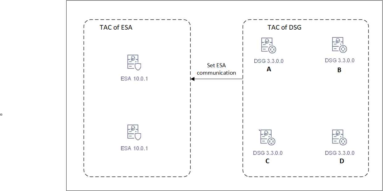
Starting DSG 3.3.0.0, separate cluster for ESAs and DSGs are created. Separate clusters are required for each unique DSG major/minor version. Different major/minor versions of DSGs must not be combined in a single TAC. DSGs and ESAs should not be combined in a TAC. Use the set ESA communication utility to link DSGs to ESA.
While running the install or the upgrade process, add the FQDN of the ESAs and DSGs in the hosts file of every node in the cluster. In the upcoming releases, multiple clusters can be created. Using TAC labels, one can identify to which cluster a node belongs to. A TAC label can be added from the CLI Manager. For more information about adding a TAC label, refer to Updating Cluster Information using the CLI Manager.
The DSG cluster can be viewed from the Cluster screen on the ESA UI. On the UI, go to Cloud Gateway > 3.3.0.1 {build number} > Cluster. The DSG nodes in the cluster are displayed.
This setup of TAC sets a stage for the upcoming releases, where DSGs can communicate with various versions of ESAs.
In a cluster, ESA communicates with a healthy DSG. However, if the DSG is unhealthy or removed from the cluster, the communication might be lost. The ESA must connect to a DSG to deploy the policies and CoP packages. If the connection attempts fails, it tries to reconnect with another healthy DSG in the cluster. The ksa.json file displays the number of attempts ESA can take to establish a connection with the cluster. In this file, configure the retries parameter to set the maximum number of attempts by ESA. Once connected, the communication is established again and configurations can be deployed in the cluster. The default maximum number of retries attempts is 3. It may be adjusted by updating the retry_count value in the ksa.json file.
If DSG is upgraded from versions prior to 3.3.0.0, run the following commands on any one DSG in the cluster. These commands gather and store the details of all DSGs in the cluster. The details are then used to create a cluster of DSGs. This operation must be performed only on DSGs of v3.2.0.1 and lower. This must not be performed on DSG 3.3.0.0
tar zxvfp DSG_PAP-ALL-64_x86-64_3.3.*UP.pty --strip-components=1 -C . installer/alliance_gateway_migration_scripts_v3.9.2.tgztar zxvfp alliance_gateway_migration_scripts_v3.*.tgz ./create_tac_nodes.pycpython create_tac_nodes.pyc --save-dsg-details -f FILE
After the DSGs are upgraded, run the following command.
python create_tac_nodes.pyc --create-dsg-tac -f FILE --max-retries 60 --wait-time 5
Where,
--max-retries: The maximum number of retries for verifying a newly added node on a DSG that is already part of DSG TAC. The default value is 60 and maximum and minimum value can be set to 100 and 12 retries respectively.--wait-time: The maximum duration for sleep time between the retries, The defaults value is 5 seconds and maximum and minimum value can be set to 60 and 1 seconds respectively.
The
create_DSG_TAC.logfile is created that displays the log of the events while creating a TAC.
9 - Upgrading to DSG 3.3.0.1
The DSG v3.3.0.1 can be upgraded on an on-premise or cloud platforms. It can be upgraded to 3.3.0.1 from the following versions:
- 3.3.0.0
- 3.2.0.1
- 3.2.0.0
- 3.1.0.x (3.1.0.0 through 3.1.0.6)
- 3.0.0.0
Upgrading DSG and ESA
The DSG patch in ESA is added to extend the DSG functionality on ESA. It allows ESA to deploy configurations to other DSG nodes. The following figure illustrates DSG component upgrade on ESA.
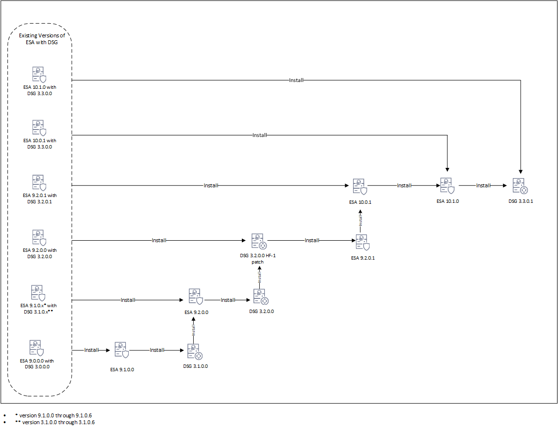
The following figure illustrates the DSG upgrade.
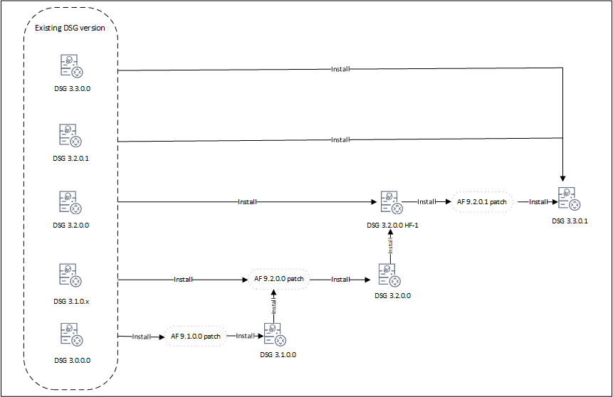
Upgrade process
Upgrading the DSG version involves a series of steps that must be performed on ESA and DSG. The following order illustrates the upgrade process.
Before you begin
Ensure that DSG and ESA are backed up. For more information about backing up, refer to Backing up from the Web UI.
Ensure that communication is established between the ESA and DSG.
Ensure that DSGs and ESA are in a cluster. All the DSGs in the cluster are healthy.
Ensure that ESAs and DSGs are accessible through their hostnames. If not, refer to Update Host Details for the detailed steps.
Ensure that the buffer folders in
/opt/protegrity/fluent-bit/data/buffer/tcp.<n>and/opt/protegrity/td-agent/es_bufferare empty. If these folders are not empty, check for errors in/var/log/td-agent/td-agent.logor/opt/protegrity/fluent-bit/data/logforwarder.log.Record any configurations added to the
/opt/protegrity/alliance/config/features.jsonfile. These configurations will not be retained after the upgrade.Ensure that configurations in the
pepserver.cfgare saved for each DSG node in the cluster. These configurations must be manually set after upgrade. For more information about the PEP server, refer to Managing PEP serverConfigure Ruleset definitions on the ESA to push the same configuration to all cluster nodes. Perform any import/export of DSG and Ruleset configurations from the ESA Web UI only.
In DSG, the custom files related to LogForwarder are placed in the
/opt/protegrity/fluent-bit/data/config.ddirectory. These files can be configured as required. When the the upgrade is in process, DSG backs up the custom LogForwarder files. The files are moved to the/opt/protegrity/fluent_backupdirectory. However, after the upgrade is completed, the files are not automatically restored to the/opt/protegrity/fluent-bit/data/config.ddirectory. All the custom configuration files and the modifications to existing default configuration files done before upgrade must to be manually applied after upgrade.
Export/import of DSG configurations and Ruleset configurations to DSG v3.3.0.1 is supported only from DSG v3.0.0.0 and higher. Do not import DSG Ruleset backups (
.zip) from older DSG versions into DSG v3.3.0.1. Navigate to Settings > Backup & Restore to export/import the DSG configurations.
If Codebook reshuffling is used, back up the following files on each DSG node:
random.dat(BLOB)dps.envuserpin.bin(User PIN)
After backing up the files, create a
.tgzfile using the following command.tar --same-owner -zcpvf /products/uploads/<filename>.tgz \ /opt/protegrity/defiance_dps/data/random.dat \ /opt/protegrity/defiance_dps/data/userpin.bin \ /opt/protegrity/defiance_dps/bin/dps.envRun the following command to set the required permissions for downloading the
.tgzpackage from the DSG Web UI.chmod 644 /products/uploads/<filename>.tgzPerform the following steps to download the .tgz package from the DSG Web UI.
- Login to the DSG Web UI.
- On the DSG Web UI, navigate to Settings > System > File Upload.
- Select the .tgz file from the Uploaded Files drop-down and click Download.
Save the details of the TAC before starting the upgrade. For more information about the TAC, refer to Trusted Appliances Cluster.
Uploading and Installing the Patch
The patch can be uploaded from the CLI Manager or the Web UI.
Uploading patch from Web UI.
- Log in to the Web UI with administrator credentials.
- Navigate to Settings > System > File Upload.
- In the File Selection section, click Choose File.
- Select the patch file and click Open. Only the files with .pty and .tgz extensions can be uploaded.
- Click Upload.
Uploading patch from CLI Manager
- Log in to the CLI Manager with administrator credentials.
- Navigate to Administration > OS Console to upload the patch.
- Enter the root password and click OK.
- Upload the patch to the
/opt/products_uploadsdirectory using the FTP or SCP command.
Perform the following steps to install the patch from the CLI Manager.
- Log in to the CLI Manager with administrator credentials.
- Navigate to Administration > Patch Management to install the patch.
- Enter the root password and click OK.
- Select Install a Patch.
- Select the required patch and select Install.
Upgrading to DSG v3.3.0.1 from DSG v3.3.0.0
Steps to upgrade to DSG v3.3.0.1 from DSG v3.3.0.0.
Prerequisites
Ensure that ESA v10.0.1 or ESA 10.1.0 is available with the DSG v3.3.0.0 patch applied on it.
Ensure that DSG v3.3.0.0 is available.
Upgrade Procedure
- Install the
ESA_PAP-ALL-64_x86-64_10.1.0.xxxx.DSGUP.3.3.0.1.x.DSGUPpatch.
Install the
ESA_PAP-ALL-64_x86-64_10.1.0+P.xxxxpatch.Install the
ESA_PAP-ALL-64_x86-64_10.1.0.xxxx.DSGUP.3.3.0.1.x.UPpatch.
- Install the
DSG_PAP-ALL-64_x86-64_3.3.0.1.xxxxpatch.
Ensure that all the required nodes are upgraded to v3.3.0.1. After installing the patches perform the post upgrade steps.
Upgrading to DSG v3.3.0.1 from DSG v3.2.0.1
Steps to upgrade to DSG v3.3.0.1 from DSG v3.2.0.1.
Prerequisites
Ensure that ESA v9.2.0.1 is available with the DSG v3.2.0.1 patch applied on it.
Ensure that DSG v3.2.0.1 is available.
Upgrade Procedure
Install the
ESA_PAP-ALL-64_x86-64_10.0.1+UP.xxxxpatch.Install the
ESA_PAP-ALL-64_x86-64_10.1.0+P.xxxxpatch.Install the
ESA_PAP-ALL-64_x86-64_10.1.0.xxxx.DSGUP.3.3.0.1.x.ptypatch.
- Install the
DSG_PAP-ALL-64_x86-64_3.3.0.1.xxxxpatch.
Ensure that all the required nodes are upgraded to v3.3.0.1. After installing the patches perform the post upgrade steps.
Upgrading to DSG v3.3.0.1 from DSG v3.2.0.0
Steps to upgrade to DSG v3.3.0.1 from DSG v3.2.0.0.
Prerequisites
Ensure that ESA v9.2.0.0 is available with the DSG v3.2.0.0 patch applied on it.
Ensure that DSG v3.2.0.0 is available.
Upgrade Procedure
Install the
DSG_PAP-ALL-64_x86-64_3.2.0.0.x.HF-1patch.Install the
ESA_PAP-ALL-64_x86-64_9.2.0.1.xxxx-UPpatch.Install the
ESA_PAP-ALL-64_x86-64_10.0.1+UP.xxxxpatch.Install the
ESA_PAP-ALL-64_x86-64_10.1.0+P.xxxxpatch.Install the
ESA_PAP-ALL-64_x86-64_10.1.0.xxxx.DSGUP.3.3.0.1.x.ptypatch.
Install the
DSG_PAP-ALL-64_x86-64_3.2.0.0.x.HF-1patch.Install the
AF-9201patch.Install the
DSG_PAP-ALL-64_x86-64_3.3.0.1.xxxxpatch.
Ensure that all the required nodes are upgraded to v3.3.0.1. After installing the patches perform the post upgrade steps.
Upgrading to DSG v3.3.0.1 from DSG v3.1.0.x
Steps to upgrade to DSG v3.3.0.1 from any of the following DSG versions:
- 3.1.0.0
- 3.1.0.2
- 3.1.0.3
- 3.1.0.4
- 3.1.0.5
- 3.1.0.6
Prerequisites
Ensure that ESA v9.1.0.x is available with the corresponding DSG v3.1.0.x patch applied on it.
Ensure that corresponding DSG v3.2.0.x is available.
Upgrade Procedure
Install the
ESA_PAP-ALL-64_x86-64_9.2.0.0.xxxx-UPpatch.Install the
DSG_PAP-ALL-64_x86-64_3.2.0.0.x.UPpatch.Install the
DSG_PAP-ALL-64_x86-64_3.2.0.0.x.HF-1patch.Install the
ESA_PAP-ALL-64_x86-64_9.2.0.1.xxxx-UPpatch.Install the
ESA_PAP-ALL-64_x86-64_10.0.1+UP.xxxxpatch.Install the
ESA_PAP-ALL-64_x86-64_10.1.0+P.xxxxpatch.Install the
ESA_PAP-ALL-64_x86-64_10.1.0.xxxx.DSGUP.3.3.0.1.x.ptypatch.
Install the
AF 9.2.0.0patch.Install the
DSG_PAP-ALL-64_x86-64_3.2.0.0.x.UPpatch.Install the
DSG_PAP-ALL-64_x86-64_3.2.0.0.x.HF-1patch.Install the
AF-9201patch.Install the
DSG_PAP-ALL-64_x86-64_3.3.0.1.xxxxpatch.
Ensure that all the required nodes are upgraded to v3.3.0.1. After installing the patches perform the post upgrade steps.
Upgrading to DSG v3.3.0.1 from DSG v3.0.0.0
Steps to upgrade to v3.3.0.1 from DSG v3.0.0.0.
Prerequisites
Ensure that ESA v9.0.0.0 is available with the corresponding DSG v3.1.0.0 patch applied on it.
Ensure that DSG v3.0.0.0 is available.
Upgrade Procedure
Install the
ESA_PAP-ALL-64_x86-64_9.1.0.0.xxxx-UPpatch.Install the
ESA_PAP-ALL-64_x86-64_9.1.0.0.xxxx.DSGUPpatch.Install the
ESA_PAP-ALL-64_x86-64_9.2.0.0.xxxx-UPpatch.Install the
ESA_PAP-ALL-64_x86-64_9.2.0.0.xxxx.DSGUPpatch.Install the
DSG_PAP-ALL-64_x86-64_3.2.0.0.x.HF-1patch.Install the
ESA_PAP-ALL-64_x86-64_9.2.0.1.xxxx-UPpatch.Install the
ESA_PAP-ALL-64_x86-64_10.0.1+UP.xxxxpatch.Install the
ESA_PAP-ALL-64_x86-64_10.1.0+P.xxxxpatch.Install the
ESA_PAP-ALL-64_x86-64_10.1.0.xxxx.DSGUP.3.3.0.1.x.ptypatch.
Install the
AF 9.1.0.0patch.Install the
DSG_PAP-ALL-64_x86-64_3.1.0.0.x.UPpatch.Install the
AF-9.2.0.0patch.Install the
DSG_PAP-ALL-64_x86-64_3.2.0.0.x.UPpatch.Install the
DSG_PAP-ALL-64_x86-64_3.2.0.0.x.HF-1patch.Install the
AF-9201patch.Install the
DSG_PAP-ALL-64_x86-64_3.3.0.1.xxxxpatch.
Ensure that all the required nodes are upgraded to v3.3.0.1. After installing the patches perform the post upgrade steps.
Post Upgrade Steps
The post upgrade steps must be performed only after each DSG node is upgraded to v3.3.0.1. Run the following steps after upgrade is completed.
Log forwarder custom files backed up during upgrade are restored.
If Codebook reshuffling is used, restore the following files on each DSG node:
random.dat(BLOB)dps.envuserpin.bin(User PIN)
For more information about restoring the files, refer to Restore Backed up Files for Codebook Reshuffling.
Scheduled tasks related to DSG on the Audit Store are enabled. The DSG metrics logs that are generated over time can be scheduled for cleanup regularly. Click Audit Store > Analytics > Scheduler, select the Delete DSG Error Indices, Delete DSG Usage Indices, or Delete DSG Transaction Indices, and then click Edit to modify the scheduled task that initiates the Indices file cleanup at regular intervals. The scheduled task can be set to n days based on your preference.
The blocked_modules and blocked_methods added in the
gateway.jsonfile before upgrade are retained after the DSG is upgraded. However, it is recommended to use the allowed modules and methods for enhanced security. For more information about blocked and allowed modules, refer toPEP server configurations for the respective DSG nodes are added in the
pepserver.cfgfile. For more information about the PEP server, refer to Managing PEP server.Run the command to create a trusted appliances cluster. For more information about the creating TAC, refer to Trusted Appliances Cluster.
If any changes are made on a DSG node in the cluster, then create a scheduler task to replicate policies, configuration, DSG rulesets, and so on, from the DSG having changes to the other DSGs in the cluster.
Run the set ESA communication on the DSG nodes. For more information, refer to Setting up ESA communication.
Ensure that the primary DSG node is registered with all ESA nodes. For more information about registering DSG, refer to Registering the DSG.
Canary Upgrade
In a canary upgrade, the DSG nodes are re-imaged to v.3.3.0.0. The DSG image is installed afresh on an existing or a new system.
Before proceeding with the upgrade, back up the PEP server configuration from the DSG nodes. Run the following steps.
- Login to the DSG Web UI.
- Navigate to Settings > System.
- Under the Files tab, download the
pepserver.cfgfile. - Repeat step 1 to step 3 on each DSG node in the cluster.
Consider the following figure.
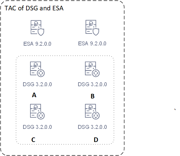
Run the following steps on ESA A.
- Remove the ESA A from the cluster.
- Upgrade the ESA A to v10.1.x.
- If the ESA is not accessible through host name, add the following host details:
- Host details of ESA B.
- Host details of node A, node B, node C, and node D.
- Create a cluster.
Run the following steps on node A.
- Remove node A from the cluster.
- Re-image the node A to v3.3.0.0.
- If the ESA is not accessible through host name, add the following host details:
- Host details of ESA A and B.
- Host details of node B, node C, and node D.
- Run the set communication for node A to communicate with the upgraded ESA A.
- Restore the
pepserver.cfgfile that was backed up for node A. - Create a cluster on the node.
Run the following steps on node B.
- Remove node B from the cluster.
- Re-image node B to v 3.3.0.0.
- If the ESA is not accessible through host name, add the following host details:
- Host details of ESA A and B.
- Host details of node A, node C, and node D.
- Restore the
pepserver.cfgfile backed up for node B. - Join node B to the cluster created on node A.
Run the following steps on node C.
- Remove node C from the cluster.
- Re-image node C to v 3.3.0.0.
- If the ESA is not accessible through host name, add the following host details.
- Host details of ESA A and B.
- Host details of node A, node B, and node D.
- Restore the
pepserver.cfgfile backed up for node C. - Join node C to the cluster created on node A.
Run the following steps on node D.
- Remove node D from the cluster.
- Re-image node D to v 3.3.0.0.
- If the ESA is not accessible through host name, add the following host details.
- Host details of ESA A and B
- Host details of node A, node B, and node C.
- Restore the
pepserver.cfgfile that was backed up for node D. - Join node D to the cluster created on node A.
Run the following steps on ESA B.
- Remove node D from the cluster.
- Upgrade ESA B to v10.1.x.
- If the ESA is not accessible through host name, add the following host details:
- Host details of ESA A.
- Host details of node A, node B, node C, and node D.
- Join ESA B to the cluster created on ESA A.
The following figure illustrates the upgraded setup.
9.1 - Post installation/upgrade steps
Verifying the DSG installation
This section describes the steps to verify the version details of the DSG instance.
To verify the version details of the DSG instance:
Login to the DSG Web UI.
Click the
(Information) icon, and then click About.Verify that the DSG version is reflected as DSG 3.3.0.1.
Pushing the DSG rulesets
This section describes the steps to push the DSG Rulesets in a cluster.
To push the DSG Rulesets:
Login to the ESA Web UI using the administrator credentials.
Navigate to Cloud Gateway > 3.3.0.1 {build number} > Cluster.
Go to Actions and click Deploy or Deploy to Node Groups to push the DSG Ruleset configurations to the DSG nodes. For more information about deploying the configurations, refer to the sections Deploying the Configurations to Entire Cluster or Deploying the Configurations to Node Groups.
The DSG Rulesets are pushed to the DSG nodes in a cluster or node groups.
Verifying the Startup Logs
This section describes the steps to verify the startup logs.
To verify the DSG startup logs:
Login to the DSG Web UI using the administrator credentials.
Navigate to Logs > Appliance.
Click Cloud Gateway - Event Logs, and select gateway.
Verify that the startup logs do not display any errors.
The DSG startup logs are displayed on the DSG Web UI.
Enabling Scheduled Tasks on Audit Store
The DSG metrics logs that are generated over time can be scheduled for cleanup regularly. You can click Audit Store > Analytics > Scheduler, select the Delete DSG Error Indices, Delete DSG Usage Indices, or Delete DSG Transaction Indices, and then click Edit to modify the scheduled task that initiates the Indices file cleanup at regular intervals. The scheduled task can be set to n days based on your preference.
For more information about the audit indexes, refer to Understanding the index field values.
For more information about scheduled tasks, refer to Using the scheduler.
10 - Ascertaining the Host Address in the Server Certificates
Ascertaining the host address in the ESA server certificate
A secure communication between ESA and DSG is established through certificates. During the set ESA communication process, a field to enter the FQDN of the ESA is displayed. The value in this field must match the value provided in the SAN or the CN field of the ESA certificate. This ensures communication between ESA and DSG is secured and trusted.
Perform the following steps to retrieve the SAN/CN value from the ESA server certificate.
On the ESA CLI manager, go to Administration > OS Console.
Enter the root password, press Tab to select OK and press Enter.
Run the following command to view the ESA server certificate.
openssl x509 -in /etc/ksa/certificates/mng/server.pem -textThe ESA Server Certificate screen.
Note: This is a sample certificate with FQDN provided in the Subject Alternative Name(SAN) field or Common Name(CN) fields. The SAN and CN fields may also have the IP address.

Note down the FQDN given in the SAN or CN fields.
Exit the command prompt.
Ascertaining the host address in the DSG server certificate
A secure communication between ESA and DSG is established through certificates. During the process of applying the DSG patch on ESA, a field to enter the FQDN of the DSG is displayed. The value in this field must match the value provided in the SAN or the CN field of the DSG certificate. This ensures communication between ESA and DSG is secured and trusted.
Perform the following steps to retrieve the SAN/CN value from the DSG server certificate.
On the DSG CLI manager, go to Administration > OS Console.
Enter the root password, press Tab to select OK and press Enter.
Run the following command to view the DSG server certificate.
openssl x509 -in /etc/ksa/certificates/mng/server.pem -textThe DSG Server Certificate screen.
Note: This is a sample certificate with FQDN provided in the Subject Alternative Name(SAN) field or Common Name(CN) fields. The SAN and CN fields may also have the IP address.

Note down the FQDN given in the SAN or CN fields.
Exit the command prompt.
11 - Setting up ESA Communication
Set ESA communication in cases, such as, change of the ESA IP address, change of the ESA certificates, adding the ESA IP address for cloud platforms, and joining the DSG in an existing cluster.
Note: Ensure that SSL synchronization is performed only once. If you are performing the ESA communication step multiple times, it is recommended to skip SSL synchronization.
Before you begin
Ensure that the TAC is created on the ESA.
Ensure that Analytics component is initialized on the ESA. The initialization of Analytics component is required for displaying the Audit Store information on Audit Store Dashboards.
For more information about initializing Analytics, refer Initializing Analytics on the ESA.
On the DSG CLI Manager, navigate to Tools > ESA Communication.
Enter the root password, press Tab to select OK and press Enter.
Select all the options, press Tab to select Set Location Now and press ENTER.
The ESA Location screen appears.

Enter the FQDN of the primary ESA or Proxy. Press Tab to select OK and press Enter.
Note: For more information about checking the ESA host address, refer to the section Ascertaining the host address in the ESA server certificate
The ESA selection screen appears.

Enter the FQDN of the primary ESA or Proxy and provide the ESA administrator credentials in the Username and Password text boxes. Press Tab to select OK and press Enter.
The Enterprise Security Administrator - Admin Credentials screen appears.

Enter the FQDN of the primary ESA for the Target Audit Store, as specified in step 4. Press Tab to select OK and press ENTER.
The Forward Logs to Audit Store screen appears.

Note: You must specify the IP addresses for all the ESAs already configured and then enter the IP for the additional ESA.
Select the type of the Host. If ESA is configured behind a proxy, select Proxy and click OK. Otherwise, choose ESA to communicate directly with the ESA machine.
The Host Address Confirmation screen appears.

Enter the FQDN of the ESA or Proxy. Press Tab to select OK and press Enter.
The Update Host Settings for DSG screen appears.

After successfully establishing the connection with the ESA, the following summary dialog box appears. Press Tab to select OK and press Enter.

The ESA communication is established successfully between the DSG and the ESA.
Note: Ensure that the Log Forwarder services are running on the DSG after completing ESA communication. To verify the service status, navigate to System > Services on the DSG Web UI.
12 - FAQs for DSG
This section lists the FAQs for DSG.
| Topic | Question | Answer |
|---|---|---|
| DSG TAC | How many DSG nodes can be registered with the ESA nodes? | Only one DSG node should be registered with all the ESA nodes |
| What if the registered DSG node is down? | ESA will be registered to the another healthy node in the DSG cluster. | |
| What if the I want to change the registered DSG from DSG Node-1 to DSG Node-2? | Perform the Registering the DSG steps. Also, Ensure that the newly added DSG node is registered with all ESA nodes. | |
| What steps should be performed if all the DSG nodes are removed from the DSG-DSG TAC? | Perform the following steps:
| |
| Log Files | How to check the history of installed patches on ESA or DSG? | Perform the following steps.
|
| How to check the Container log file? | Perform the following steps.
| |
| How to check the DSG Registration log file? | Perform the following steps.
| |
| How to check the DSG Patch installation log file? | Perform the following steps.
| |
| How to check the ESA communication log file? | Perform the following steps.
|
13 - Web UI
The DSG Web UI is a collection of DSG-specific UI screens under Cloud Gateway menu that are part of the ESA Web UI. The Cloud Gateway menu is enabled after the ESA patch for Cloud Gateway is installed in ESA.
The ESA dashboard is as seen in the following figure.

The Cloud Gateway menu contains the following sub-menus:
Cluster
- Monitoring: View all the nodes in a cluster. Add, delete, start, stop, and apply patches to node(s) in the cluster.
- Log Viewer: View consolidated logs across all DSG nodes.
Ruleset
- Ruleset: View the hierarchical set of rules. The rules are defined for each profile that is created under a service.
- Learn Mode: View the hierarchical processing of a rule that is affected due to a triggered transaction request or response.
Transport
- Certificates: View the certificates generated by or uploaded to the DSG.
- Tunnels: View the list of protocol-specific tunnels configured on the DSG.
Global Settings
- Debug: Configure log settings, Learn mode settings, and set configurations that enable administrative queries.
- Global Protocol Stack: Apart from the settings that you configure for each service type, some settings affect all services that relate to a protocol type.
- Web UI: The Web UI tab lets you configure additional settings that impact how the UI is displayed.
Test Utilities: The test utilities provide an interface where you can select the data security operation you want to perform, along with the DSG node, data elements available in the policies deployed at that node, and an external IV value for added security layer. This menu is available only for users with the policy user permission.
Note: The Tunnel and Ruleset configurations can be created on ESA and DSG. However, it is recommended to create the Tunnel and Ruleset configurations on the ESA. This allows the same configuration to be pushed simultaneously to all the ESA and DSG nodes in the cluster. If these configurations are created only on DSG, it can be overridden by the configuration created on the ESA.
13.1 - Cluster
The Cluster menu includes the following tabs: Monitoring and the Log Viewer tabs.
Monitoring: The Monitoring tab displays information about the available nodes in a DSG cluster.
Log Viewer: Unified view of the log messages across all the nodes in the cluster.
13.1.1 - Monitoring
The individual nodes in the cluster can be monitored and managed. The following actions are available on the monitoring screen:
Add nodes to the cluster
Deploy configurations to the nodes in the cluster
Deploy configurations to specific node groups
Change groups in the cluster
Change groups on selected nodes
Refresh nodes in the cluster
Start, stop, or restart individual nodes
The following figure illustrates the Monitoring screen:

1 Cluster Health - Cluster health indicator in Green, Orange, or Red.
2 Hostname - Hostname of the DSG.
3 IP - IP address of the DSG.
4 PAP version - Build version of the DSG.
5 Health - Status of DSG.
6 Node Group - Node group assigned to the DSG node. If no node group is specified, the node group is assigned as default.
7 Config Version - The tag name provided while deploying the configuration to a particular node group.
8 DSG Version - Build version of DSG.
9 Uptime - Time that the DSG has been running.
10 Load Avg - Average load on a process in the last five, ten, and fifteen minutes.
11 Utilization - Number of DSG processes and CPU cores utilized.
12 Connections - Total number of active connections for the node.
13 Select for Patch Installation or Node Group Update - Select the option to updating the node group
14 Socket - Total number of open sockets for the node.
15 Config Version Description - The additional information about the configuration version. If the description is not provided while deploying the configurations to a particular node group, then this field will be empty.
Cluster and node health status color indication reference:
| Color | Description |
|---|---|
 | Node is healthy and services are running. |
 | Warning. Some services related to a node need attention. |
 | Not running or unreachable. |
The following figure illustrates the actions for the Cluster Monitoring screen.

The callouts in the figure are explained as follows.
1 Expand - Expand to view the other columns.
2 Refresh - Refresh all the nodes in the cluster.
Note: Allow a short wait time between two different cluster operations to ensure changes are properly reflected in the ESAs and DSGs.
The Refresh drop down list provides the following options:
- Start: Starts all nodes.
- Stop: Stops all nodes.
- Refresh: Refreshes details related to all nodes.
- Restart: Restarts all nodes. The restart operation will not export the configurations, it will only restart all the nodes.
- Deploy: Deploys the configuration changes on all the DSG nodes in the cluster. The configurations are pushed and the node is restarted. For more information, refer to the section Deploying Configurations to the Cluster.
- Deploy to Node Groups: Deploy the configurations to the selected node groups in the cluster. The configurations are pushed and the node is restarted. For more information, refer to the section Deploy Configurations to Node Groups.
3 Actions - The Actions drop down list at the cluster level provides the following options:
Note: Allow a short wait time between two different cluster operations to ensure changes are properly reflected in the ESAs and DSGs.
- Apply Patch on Cluster: Applies a patch to all nodes in a cluster including the ESA.
- Apply Patch on Selected Nodes: Apply the same patch simultaneously on all selected nodes.
- Change Groups on Entire Cluster: Change the node group of all the DSG nodes in the cluster
- Change Groups on Selected nodes: Select the node and change the node group on that particular DSG node in the cluster
- Add Node: Adding a Node to the Cluster.
4 Order - Sort the nodes in ascending or descending order
5 Actions - The Actions drop down list at the individual node level provides the following options:
Note: Allow a short wait time between two different cluster operations to ensure changes are properly reflected in the ESAs and DSGs.
- Start: Start a node
- Stop: Stop a node
- Restart: Restart a node.
- Apply Patch: Applies a patch to a single node. Before applying a patch on a single DSG node, ensure that the same patch is applied on the ESA.
- Change Groups: Changes the node group on an individual DSG node
- Delete: Delete a node.
Deploying the Configurations to Entire Cluster
The configurations can be pushed to all the DSG nodes in the cluster. This action can be performed by clicking the Deploy option on the Cluster page or from the Ruleset page.
To deploy the configurations to entire cluster:
In the ESA Web UI, navigate to Cloud Gateway > 3.3.0.1 {build number} Cloud Gateway > 3.3.0.1 {build number} > Cluster.
Select the Refresh drop down menu and click Deploy.
The following pop-up message occur on the Cluster screen.

Click YES to push the configurations to all the node groups and nodes.
The configurations will be deployed to all the nodes in the entire cluster.
Deploying the Configurations to Node Groups
The configurations can be pushed to the selected node groups. The configuration will only be pushed to the DSG nodes associated with the node groups. This action can be performed by clicking the Deploy to Node Groups option on the cluster page or from the Ruleset page.
To deploy the configurations to the selected node groups:
In the ESA Web UI, navigate to **Cloud Gateway > 3.3.0.1 {build number}**Cloud Gateway > 3.3.0.1 {build number}> Cluster.
Select the Refresh drop down menu and click Deploy to Node Groups.
Perform the following steps to deploy the configurations to the node groups.
Click Deploy to Node Groups.
The Select node groups for deploy screen appears.

The default and lob1 are the node groups associated with the DSG nodes. When you add a node to cluster, a node group is assigned to that node. For more information about adding a node and node group to the cluster, refer to the section Adding a Node to the Cluster.
Enter the name for the configuration version in the Tag Name field.
The tag name is the version name of a configuration that is deployed to a particular node group. The tag name must be alphanumeric separated by spaces or underscores. If the tag name is not provided, then it will automatically generate the name in the YYYY_mm_dd_HH_MM_SS format.Enter the description for the configuration in the Description field. The user can provide additional information about the configuration that is to be deployed.
On the Deployment Node Groups option select the node group to which the configurations must be deployed.
Click Submit.
13.1.2 - Log Viewer
The Log Viewer screen provides a unified view of all the logs. The logs are classified in the following levels:
Debug: Debugging trace.
Verbose: Additional information that can help a user with detailed troubleshooting
Information: Log entry for information purposes
Warning: Non-critical problem. Appears in orange.
Error: Issue that requires user’s attention. Appears in red.
The following figure illustrates the column for the Log Viewer screen.

1 Host - Host name or IP address of the DSG node where the log message was generated.
2 PID - Captures the process identifier of the DSG daemons that generated the log message.
3 Timestamp (UTC) - Time recorded when an event for the log was generated. The time recorded is displayed in the Coordinated Universal Time (UTC) format.
4 Level - Severity level of the log message.
5 Module - Part of the program that generated the log.
6 Source - Procedure in the module that generated the log.
7 Message - A textual description of the event logged.
The following figure illustrates the actions for the Log Viewer screen.

Search logs
Click the search box to scan through the log archive that is collectively maintained across all the DSG nodes within the cluster. The search for logs is not limited to the records that appear on the screen. When a user clicks search, all the log records that are present on the screen as well as on the server are retrieved.
Clear records
You can use the clear functionality to clean up the logs and view the newly generated logs on the Log Viewer screen. Clearing the Log Viewer screen removes the entries that are currently displayed. You can view all the archived logs even after the records are cleared.
The logs are cleared only from the Log Viewer screen. The logs are not cleared or deleted from the appliance and are available for future reference. To access these logs, on the DSG node, click Logs > Appliance. Under Cloud Gateway - Event Logs, select gateway.
Retrieve archived logs
When the logs are cleared from the screen, the records are archived and can be viewed later. After clearing the records, click the Refresh icon. A link displaying the timestamp of the last updated record appears. Click Showing logs after
Fetching records
Click the Refresh icon to view new logs generated.
13.2 - Ruleset
The RuleSet menu includes the RuleSet and the Learn Mode tabs.
- RuleSet tab
The Ruleset tab provides you the capability to create a hierarchical rule pattern based on the service type. The changes made to the Ruleset tree require deployment of configuration to take effect. - Learn Mode
Learn Mode tab provides a consolidated view of all message recorded by the DSG cluster. It allows you to consider messages exchanged through the DSG nodes and study the payloads as they are seen by the DSG. Understanding how messages are structured enables you to set the appropriate rules which will transform the relevant parts in it before it is forwarded on.
13.2.1 - Learn Mode
The Learn Mode tab provides a consolidated view of all message recorded by the DSG cluster. It allows you to review messages exchanged through DSG nodes and examine payloads as they appear to DSG. Understanding how messages are structured enables you to define appropriate rules that transform relevant parts before the message is forwarded.
The Learn Mode tab is shown in the following figure.

The following table provides the description for each column available on the Web UI.
1 Received (UTC) - Time when the transaction is triggered. The time recorded is displayed in the Coordinated Universal Time (UTC) format.
2 PID - Process Identifier that has carried the request or response transaction on the gateway machine.
3 Source - Source IP address or hostname in the request.
4 Destination - Destination IP address or hostname in the request.
5 Service - Service name to which the transaction belongs.
6 Hostname - DSG node hostname where the request was received and processed.
7 Message - Provides information about the type of message.
8 Processing Time (ms) - Time required to complete the transaction.
9 Rules Filters - Filter the rules based on the selected option for a transaction.
10 Filter Summary - Summary of rule details, such as, Elapsed time, result, and Action Count.
11 Message Difference - Difference between the message received by the rule and the message processed by the rule.
12 Wrap lines - Select to break the text to fit in the readable view.
13 View in Binary - View message in hexadecimal format.Note: If you want to view a payload such as .zip, .pdf, or more, you can use the View in Binary option.
14 Download Payload - Click to download large payloads that cannot be completely displayed on the screen.
** Failed Transaction (in red color) - Any failed transaction is highlighted in the color red.
The following figure illustrates the actions on the Learn Mode screen.

The following table provides the description for each action available on the Web UI.
1 Search log - Search the learn mode content.
2 Column Filters - Apply column filters for each column to filter or search records based on the string and regex pattern match.
3 Refresh - Refresh the list.
4 Reset - Logs from the server are purged.
5 Collapse/Expand tree - Collapse or expand the rule tree.
You can select a record in the Learn Mode screen to view details regarding the matched and unmatched rules for that entry. If the size of the message exceeds the limit, then a message Contents of the selected record are too large to be displayed appears.
13.2.1.1 - Learn Mode Scheduled Task
Click System > Task Scheduler, select the Learn Mode Log Cleanup scheduled task, and then click Edit to modify the scheduled task that initiates the learnmodecleanup.sh file at regular intervals. The scheduled task can be set to n hours or days based on your preference. The default recommended frequency is Daily-Every Midnight.
In addition to setting the task, you can define the duration for which you want to archive the Learn Mode logs. The following image displays the Learn Mode Log Cleanup scheduled task.

The following table provides sample configurations:
| Frequency | Command line value | Retain the logs for | Default values |
|---|---|---|---|
| Daily-Every Midnight | /opt/protegrity/alliance/bin/scripts/learnmodecleanup.sh 10 DAYS | Last 10 DAYS | Days can be set between 1 to 66 |
| Every hour | /opt/protegrity/alliance/bin/scripts/learnmodecleanup.sh 10 HOURS | Last 10 HOURS | Hours can be set between 1 to 23 |
Note: If a numeric value is set without the HOURS or DAYS qualifier, then DAYS is considered as the default.
13.2.2 - Ruleset Tab
The changes made to the Ruleset tree require deployment of configuration to take effect.
The RuleSet tab is shown in the following figure:

The following table provides the description for each of the available RuleSet options:
1 Search - ![]() Click to search for service, profile, or rules.
Click to search for service, profile, or rules.
2 Search textbox - Provide service, profile, or rule name.
3 Add new service - Add a new service-level based on the service type used. Only one service can be created for every service type.
4 View Old Versions - Click to view archived Ruleset configuration backups.
5 Deploy - Deploy the configurations to all the DSG nodes in the cluster. The Deploy operation will export the configurations and restart all the nodes.
6 Deploy to Node groups - Deploy the configurations to the selected node groups in the cluster. This will export the configurations and restart the nodes associated with the node groups.
7 Import - Import the Ruleset tree to the Web UI. Files should be uploaded in .zip extension structure.
- Ensure that the service exists as part of the Ruleset before you import a configuration exported at Profile level.
- Ensure that the directory structure that the exported .zip maintains is replicated when you repackage the files for import. Also, the JSON files must be valid.
- If an older ruleset configuration .zip created using any older DSG version, that includes a GPG ruleset with key passphrase defined, is imported, then the DSG does not encrypt the key passphrase.
8 Export All - Export the Ruleset tree configuration. The rules are downloaded in a .zip format.
9 Edit - Edit the service, profile, or rule details as per requirement.
10 Expand Rule![]() - Expand the rule tree and view child rules.
- Expand the rule tree and view child rules.
If you want to further work with rules, right-click any rule to view a set of sub menus. The sub menu options are seen in above figure. The options are described in the following table.
11 Duplicate![]() - Duplicate a service, profile, or rule to create a copy of these Ruleset elements.
- Duplicate a service, profile, or rule to create a copy of these Ruleset elements.
12 Export ![]() - Export the Ruleset tree configuration at Service or Profile level. All the child rules under the parent Service or Profile are exported. The rules are downloaded in the .zip format.
- Export the Ruleset tree configuration at Service or Profile level. All the child rules under the parent Service or Profile are exported. The rules are downloaded in the .zip format.
13 Create Rule![]() - Add child rule under the parent rule.
- Add child rule under the parent rule.
14 Delete ![]() - Delete the selected rule.
- Delete the selected rule.
15 Cut ![]() - Cut the selected rule from the parent rule.
- Cut the selected rule from the parent rule.
16 Copy ![]() - Copy the selected rule under a parent.
- Copy the selected rule under a parent.
17 View Configuration ![]() - View the configuration of the rule in the JSON format. You can copy the JSON format of the rule and pass it as parameter value in the header of the Dynamic CoP ruleset. This option is available only for the individual rules.
- View the configuration of the rule in the JSON format. You can copy the JSON format of the rule and pass it as parameter value in the header of the Dynamic CoP ruleset. This option is available only for the individual rules.
Instead of cut and copy a rule to change its hierarchy among siblings, you can also drag a sibling rule and change its positioning. When the drop is successful, a green tick icon (![]() ) is displayed as shown in the following figure.
) is displayed as shown in the following figure.

When the drop is unsuccessful, a red cross icon ( ![]() ) is displayed as shown in the following figure.
) is displayed as shown in the following figure.

A log is generated in the Forensics screen every time you cut, copy, delete, or reorder a rule from the Ruleset screen in the ESA.
The following figure shows a service with Warning indication.

The ![]() symbol is seen on the service when the child rule is not created or when Learn Mode is enabled.
symbol is seen on the service when the child rule is not created or when Learn Mode is enabled.
Deploy configurations to the Cluster
In the ESA Web UI, navigate to Cloud Gateway > 3.3.0.1 {build number} > Ruleset.
Click Deploy. A confirmation message occurs.
Click Continue to push the configurations to all the node groups and nodes. The configurations will be deployed to the entire cluster.
Deploy configurations to node groups
In the ESA Web UI, navigate to Cloud Gateway > 3.3.0.1 {build number} > Ruleset.
Click Deploy > Deploy to Node Groups.
The Select node groups for deploy screen appears.
Enter the name for the configuration version in the Tag Name field. The tag name is the version name of a configuration that is deployed to a particular node group. The tag name must be alphanumeric, separated by spaces or underscores. If the tag name is not provided, then it will automatically generate the name in the YYYY_mm_dd_HH_MM_SS format.
Enter the description for the configuration in the Description field.
On the Deployment Node Groups option, select the node group to which the configurations must be deployed.
Click Submit.
The configurations are deployed to the node groups.
13.2.2.1 - Ruleset Versioning
What is it
After deploying a configuration to a particular node group or to an entire cluster, a backup of these configurations are saved in View Older Versions on the Ruleset page. The most recent deployed configuration for a particular node group is shown with a Deployed status when viewing the older versions There are tagged and untagged versions seen when viewing the older versions. You can create a tagged or untagged version.
The following figure shows the Ruleset versioning screen.

The following table provides the description for the deployed configurations.
1 The configuration is deployed to the default node group and you can see the Deployed status for this configuration version. This is the most recent deployed configuration version for the default node group with Deployed status. Each node group will have a Deployed status for the most recent configuration version.
2 The configuration is deployed to lob1 node group and the configuration version is untagged. As the version is untagged, it will automatically generate the name with timestamp in the YYYY_mm_dd_HH_MM_SS format. Each node group will archive the three most recent untagged version. Refer to configuring the default value.
3 The configuration is deployed to the lob1 node group and the configuration version is tagged. While deploying the configuration to default node group the lob1_fst_configuration tag name was provided to configuration versions. Each node group will archive the ten most recent tagged version. Refer to configuring the default value
Working with ruleset versioning
Each time a configuration is changed and deployed, the DSG creates a backup configuration version. You can apply an earlier configuration version and make it active, in case you want to revert to the older configuration version.
On the DSG Web UI, navigate to **Cloud Gateway > 3.3.0.1 {build number}**Cloud Gateway > 3.3.0.1 {build number}> Ruleset.
The following figure shows the Ruleset versioning screen.

Click View Old Versions.
Click the Viewing drop-down to view the available versions.
Select a version.
The left pane displays the Services, Profiles, and Rules that are part of the selected version.
Click Apply Selected Version to make the version active or click Close Old Versions to exit the screen.
Click Deploy or Deploy to Node Groups to save changes.
For more information about deploying the configurations to entire cluster or the node groups, refer Deploying the Configurations to Entire Cluster and Deploying the Configurations to Node Groups.
It is recommended that any changes to the Ruleset configuration is made through the Cloud Gateway menu available on the ESA Web UI. Any changes made to the Ruleset configuration from the DSG Web UI of an individual node are overridden by the changes made to the ruleset configuration from the ESA Web UI. After overriding, the older Ruleset configuration on individual nodes is displayed as active and no backup for this configuration is maintained.
Updating versions
If you want to change the number of tagged or untagged versions that a node can store, then on the DSG node, login to the OS console. Navigate to the
/opt/protegrity/alliance/version-1/config/webinterfacedirectory. Edit the following parameter in the nodeGroupsConfig.json file.no_of_node_group_deployed_archives = <number_of_untagged_versions_to_be_stored>The default value for the untagged version is set at 3.
no_of_node_group_deployed_tag_archives = <number_of_tagged_versions_to_be_stored>The default value for the tagged version is set at 10.
13.3 - Transport
The Transport Menu includes the Certificates and the Tunnels tabs.
The Certificates tab allows for the configuration of TLS/SSL certificates for SSL Termination by the DSG.
The Tunnels tab provide the methods to define the DSG inbound communication channels.
13.3.1 - Tunnels
The changes made to Tunnels require a cluster restart to take effect. You can either use the bundled default tunnels or create a tunnel based on your requirements.
The Tunnels tab is as seen in the following figure.

The following table provides the description of the columns available on the Web UI.
1 Name - Unique tunnel name.
2 Description - Unique description that describes port supported by the tunnel.
3 Protocol - Protocol type that the tunnel supports. The available Type values are HTTP, S3, SMTP, SFTP, NFS, and CIFS.
4 Enabled - Status of the tunnel. Displays status as true, if the tunnel is enabled.
5 Start without service - Select to start the tunnel if no service is configured or if no services are enabled.
6 Interface - IP address through which sensitive data enters the DSG. The available Listening Address options are as follows:
- ethMNG: The management interface on which the Web UI is accessible.
- ethSRV0: The service interface for communicating with an untrusted service.
- 127.0.0.1: The local loopback adapter.
- 0.0.0.0: The broadcast address for listening to all the available network interfaces over all IP addresses.
- Other: Manually add a listening address based on your requirements.
Note: The service interface, ethSRV0, listens on port 443. If you want to stop this interface from listening on this port, then edit the default_443 tunnel and disable it.
7 Port - Port linked to the listening address.
8 Certificate - Certificate applicable to a tunnel.
9 Deploy to All Nodes - Deploy the configurations to all the DSG nodes in the cluster.Deploy can also be performed from the Cluster tab or Ruleset screen. In a scenario where an ESA and two DSG nodes are in a cluster, by using the Selective Tunnel Loading functionality, you can load specific tunnel configurations on specific DSG nodes.
Click Deploy to All Nodes to push specific tunnel configurations from an ESA to specific DSG nodes in a cluster.
The following figure illustrates the actions for the Tunnels screen.

The following table provides the available actions:
1 Create Tunnel - Create a tunnel configuration as per your requirements.
2 Edit ![]() - Edit an existing tunnel configuration.
- Edit an existing tunnel configuration.
3 Delete ![]() - Delete an existing tunnel configuration
- Delete an existing tunnel configuration
13.3.1.1 - Manage a Tunnel
Create a tunnel
You can create tunnels for custom ports that are not predefined in the DSG using the Create Tunnel option in the Tunnels tab. The Create Tunnel screen is as seen in the following figure.

The following table provides the description for each option available on the UI.
| Callout | Column/Textbox | Description |
|---|---|---|
| 1 | Name | Name of the tunnel. |
| 2 | Tunnel ID | Unique ID of the tunnel. |
| 3 | Description | Unique description that describes port supported by the tunnel. |
| 4 | Enabled | Select to enable the tunnel. The check box is selected as a default. Uncheck the check box to disable the tunnel. |
| 5 | Start without service | Select to start the tunnel if no service is configured or if no services are enabled. |
| 6 | Protocol | Protocol type supported by the tunnel. |
The following types of tunnels can be created.
- HTTP
- SFTP
- SMTP
- Amazon S3
- CIFS/NFS
Edit a tunnel
Edit an existing tunnel configuration using the Edit option in the Tunnels tab. The Edit Tunnel screen is as seen in the following figure.

After editing the required field, click Update to save your changes.
Delete a tunnel
Delete an existing tunnel using the Delete option in the Tunnels tab. The Delete Tunnel screen is shown in the following figure.

The following table provides the description for each option available on the UI.
| Callout | Column/Textbox/Button | Description |
|---|---|---|
| 1 | Cancel | Cancel the process of deleting a tunnel. |
| 2 | Delete | Delete the existing tunnel from the Tunnels tab. |
13.3.1.2 - Amazon S3 Tunnel
Amazon Simple Storage Service (S3) is an online file storage web service. It lets you manage files through browser-based access as well as web services APIs. Within the DSG, the S3 tunnel is used to communicate with Amazon S3 cloud storage over the Amazon S3 REST API. The higher-layer S3 Service object, which sits above the tunnel object, configured at the RuleSet level is used to process file contents retrieved from S3.
A sample S3 tunnel configuration is shown in the following figure.

Amazon S3 uses buckets to store data and data is classified as objects. Each object is identified with a unique key ID. Consider an example that john.doe is the bucket and incoming is a folder under john.doe bucket. Assuming the requirement is that files landing in the incoming folder should be picked up and processed by DSG nodes. The data pulled from the AWS online storage is available in the incoming folder under the source bucket. The Amazon S3 Service is used to perform data security operations on this data in the source bucket.
Note: The DSG supports four levels of nested folders in an Amazon S3 bucket.
After the rules are executed, the processed data may be stored in a separate bucket (e.g. the folder named outgoing under the same john.doe bucket), which is the target bucket. When the DSG nodes poll AWS for a file uploaded, whichever node accesses the file first places a lock on the file. You can specify if the lock files must be stored in a separate bucket or under the source bucket. If the file is locked, the other DSG nodes will stop trying to access the file.
If the data operation on a locked file fails, the lock file can be viewed for detailed log and error information. The lock files are automatically deleted if the processing completes successfully.
Consider the scenario where an incoming bucket contains two directories Folder1 and Folder2.
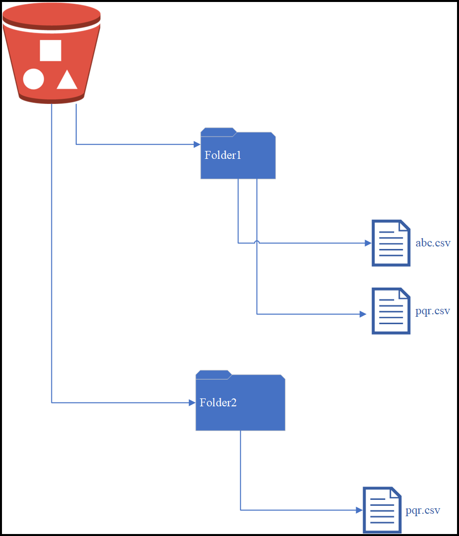
The DSG allows multiprocessing of files that are place in the bucket. The lock files are created for every file processed. In the scenario mentioned, the lock files are created as follows:
- If the abc.csv file of Folder1 is processed, the lock file is created as Folder1.abc.csv.<hostname>.<Process ID>.lock.
- If the pqr.csv file of Folder2 is processed, the lock file is created as Folder1.pqr.csv.<hostname>.<Process ID>.lock.
Consider the following figure where files are nested in the S3 bucket.
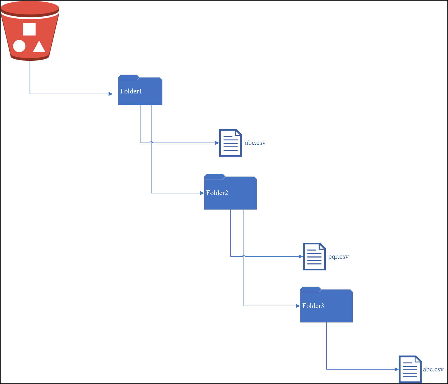
The lock files are created as follows:
- If the abc.csv file of Folder1 is processed, the lock file is created as Folder1.abc.csv.<hostname>.<Process ID>.lock.
- If the pqr.csv file of Folder2 is processed, the lock file is created as Folder1.Folder2.pqr.csv.<hostname>.<Process ID>.lock.
- If the abc.csv file of Folder3 is processed, the lock file is created as Folder1.Folder2.Folder3.abc.csv.<hostname>.<Process ID>.lock.
If the multiprocessing of files is to be discontinued, remove the enhanced-lock-filename flag from the features.json file available in the System > Files on the DSG Web UI.
The following image illustrates the options available for an S3 tunnel.

The options specific to the S3 Protocol type are described as follows:
Bucket list settings
1 Source Bucket Name: Bucket name as defined in AWS where the files that need to be processed are available.
2. Source File Name Pattern: Regex pattern for the filenames to be processed. For example, .csv.
Rename Processed Files: Regex logic for renaming processed file.
3. Match Pattern: Regex logic for renaming processed file.
4. Replace Value: Value to append or name that will be used to rename the original source file based on the pattern provided and grouping defined in regex logic.
5. Overwrite Target Object: Select to overwrite a file in the bucket with a newly processed file of the same name. Refer to Amazon S3 Object.
6. Lock Files Bucket: Name of the lock files folder, if you want the lock files to be stored in a separate bucket. If not defined, lock files are placed in the source bucket.
7. Interval: Time in secs when the DSG node will poll AWS for pulling files. You can also specify a cron job expression. Refer to Cron documentation. The default value is 5. If you use the cron job expression “* * * * *”, DSG will poll AWS at the minimum interval of one minute.
Cron job format is also supported to schedule jobs.
AWS Settings
8. AWS Access Key Id: Access key id used to make secure protocol request to an AWS service API. Refer to Amazon Web Service documentation.
9. AWS Secret Access Key: Secret access key related to the access key id. The access key id and secret access key work together to sign into AWS and provide access to resources. Refer to Amazon Web Service documentation.
10. AWS Endpoint URL: Specify the endpoint URL if it is other than the amazon S3 bucket. This parameter should only be configured if the user is using DSG to connect to other endpoint than amazon S3 bucket i.e. On-Premise S3, Google Cloud Bucket, and so on.If not defined, the DSG will connect to Amazon S3 bucket.
11. Path to CA Bundle: Specify the path to CA bundle if the endpoint is other than Amazon S3 bucket. If the user has installed the S3 on-premise using the self signed certificate, then specify that path to CA bundle in this parameter. If the endpoint URL is Amazon S3 bucket, then by default it uses SSL certificate to connect to S3 bucket.
Advanced Settings
12. Advanced settings: Set additional advanced options for tunnel configuration, if required, in the form of JSON in the following textbox. In a scenario where an ESA and two DSG nodes are in a cluster, by using the Selective Tunnel Loading functionality, you can load specific tunnel configurations on specific DSG nodes.
The advanced settings that can be configured for S3 Protocol.
| Options | Description |
|---|---|
| SSECustomerAlgorithm | If server-side encryption with a customer-provided encryption key was requested, the response will include this header confirming the encryption algorithm used. |
| SSECustomerKey | Constructs a new customer provided server-side encryption key. |
| SSECustomerKeyMD5 | If server-side encryption with a customer-provided encryption key was requested, the response will include this header to provide round-trip message integrity verification of the customer-provided encryption key. |
| ACL | Allows controlling the ownership of uploaded objects in an S3 bucket.For example, if ACL or Access Control List is set to “bucket-owner-full-control”, new objects uploaded by other AWS accounts are owned by the bucket owner. By default, the objects uploaded by other AWS accounts are owned by them. |
Using S3 tunnel to access files on Google Cloud Storage
Similar to AWS buckets, data is also stored on the Google Cloud Storage can also be protected. You can use the S3 tunnel to access the files on the GCP storage. The incoming and processed file has to be placed in the same storage in separate folders. For example, a storage named john.doe bucket contains a folder incoming that contains files to be picked and processed by DSG nodes. This acts as the source bucket. After the rules are executed, the data is stored in the processed bucket. Ensure the following points are considered.
- AWS Endpoint URL contains the URL of the Google Cloud storage.
- AWS Access Key ID and AWS Secret Access Key contain the secret ID and HMAC keys.
Refer to Google docs for information about Access ID and HMAC keys.
13.3.1.3 - HTTP Tunnel
Based on the protocol selected, the dependent fields in the Tunnel screen vary. The following image illustrates the settings that are specific to the HTTP protocol.

The options for the Inbound Transport Settings field in the Tunnel Details screen specific to the HTTP Protocol type are described in the following table.
Network Settings
1 Listening Interface: IP address through which sensitive data enters the DSG. The following Listening Interface options are available:
- ethMNG: The management interface on which the DSG Web UI is accessible.
- ethSRV0: The service interface for communicating with an untrusted service.
- 127.0.0.1: The local loopback adapter.
- 0.0.0.0: The broadcast address for listening to all the available network interfaces.
- Other: Manually add a listening address based on your requirements.
2 Port:Port linked to the listening address.
TLS/SSL Security Settings
3 TLS Enabled: Select to enable TLS features.
4 Certificate: Certificate applicable for a tunnel.
5 Cipher Suites: Colon separated list of Ciphers.
6 TLS Mutual Authentication: CERT_NONE is selected as default. Use CERT_OPTIONAL to validate if a client certificate is provided or CERT_REQUIRED to process a request only if a client certificate is provided. If TLS mutual authentication is set to CERT_OPTIONAL or CERT_REQUIRED, then the CA certificate must be provided.
7 CA Certificates: A CA certificate chain. This option is applicable only if the value client certificate is set to 1 (optional) or 2 (required). Client certificates can be requested at the tunnel and the RuleSet level for authentication. On the Tunnels screen, you can configure the ca_reqs parameter in the Inbound Transport Settings field to request the client certificate. Similarly, on the Ruleset screen, you can toggle the Required Client Certificate checkbox to enable or disable client certificates. Based on the combination of the options in the tunnel and the RuleSet, the server executes the transaction. If the certificate is incorrect or not provided, then server returns a 401 error response.
The following table explains the combinations for the client certificate at the tunnel and the RuleSet level.
| TLS Mutual Authentication (Tunnel Screen) | Required Client Certificate (Enable/Disabled) (Ruleset Screen) | Result |
|---|---|---|
| CERT_NONE | Disabled | The transaction is executed |
| Enabled | The server returns a 401 error response. | |
| CERT_OPTIONAL | Disabled | The transaction is executed |
| Enabled | If the client certificate is provided, then transaction is executed. If the client certificate is not provided, then the server returns a 401 error response. | |
| CERT_REQUIRED | Disabled | The transaction is executed |
| Enabled | The transaction is executed |
8 DH Parameters: The .pem filename that includes the DH parameters. Upload the .pem file from the Certificate/Key Material screen. The Diffie-Hellman (DH) parameters define the way OpenSSL performs the DH Key exchange.
9 ECDH Curve Name: Supported curve names for the ECDH key exchange.The Elliptic curve Diffie–Hellman (ECDH) protocol allows key agreement and leverages elliptic-curve cryptography (ECC) properties for enhanced security.
10 Certificate Revoke List: Path of the Certificate Revocation List (CRL) file. For more information about CRL error message that appears when a revoked certificate is sent, refer to the CRL error. The ca.crl.pem file includes a list of certificates that are revoked. Based on the flags that you provide in the verify_flags setting, SSL identifies certificate verification operations that need to performed. The CRL verification operations can be VERIFY_CRL_CHECK_LEAF or VERIFY_CRL_CHECK_CHAIN.
When you try to access the DSG through HTTPS using such a revoked certificate, the DSG returns the following error message.

11 Verify Flags Set to one of the following operations to verify the CRL:
- VERIFY_DEFAULT
- VERIFY_X509_TRUSTED_FIRST
- VERIFY_CRL_CHECK_LEAF
- VERIFY_CRL_CHECK_CHAIN
12 SSL Options|Set the required flags that reflect the TLS behavior at runtime. A single flag or multiple flags can be used.It is used to define the supported SSL options in the JSON format. The DSG supports TLS v1.2.|For example, in the following JSON, TLSv1 and TLSv1.1 are disabled.{|
“options”: [“OP_NO_SSLv2”,
“OP_NO_SSLv3”,
“OP_NO_TLSv1”,
“OP_NO_TLSv1_1”]
}
13 Advanced Settings Set additional advanced options for tunnel configuration, if required, in the form of JSON.|In a scenario where an ESA and two DSG nodes are in a cluster, by using the Selective Tunnel Loading functionality, you can load specific tunnel configurations on specific DSG nodes.
| Options | Description | Default (if any) | Notes |
|---|---|---|---|
| idle_connection_timeout | Timeout set for an idle connection. The datatype for this option is seconds. | 3600 | |
| max_buffer_size | Maximum value of incoming data to a buffer. The datatype for this option is bytes. | 10240000 | |
| max_write_buffer_size | Maximum value of outgoing data to a buffer. The datatype for this option is bytes. | 10240000 | This parameter is applicable only with REST streaming. |
| no_keep_alive | If set to TRUE, then the connection closes after one request. | false | |
| decompress_request | Decompress the gzip request body | false | |
| chunk_size | Bytes to read at one time from the underlying transport. The datatype for this option is bytes. | 16384 | |
| max_header_size | Maximum bytes for HTTP headers. The datatype for this option is bytes. | 65536 | |
| body_timeout | Timeout set for wait time when reading request body. The datatype for this option is seconds. | ||
| max_body_size | Maximum bytes for the HTTP request body. The datatype for this option is bytes. | 4194304 | Though the DSG allows to configure the maximum body size, the response body size will differ and cannot be configured on the DSG. The response body size that the gateway will send to the HTTP client is dependent on multiple factors, such as, the complexity of the rule, transform rule configured in case you use regex replace, size of response received from destination, and so on. If a request is sent to the client with the response body size greater than the value configured in the DSG, then the following response is returned and the DSG closes the connection: 400 Bad RequestIn earlier versions of the DSG, the DSG closed the connection and sent 200 as the response code. |
| max_streaming_body_size | Maximum bytes for the HTTP request body when HTTP streaming with REST is enabled. The datatype for this option is bytes. | 52428800 | |
| maximumBytes | This field is not supported for the DSG 3.0.0.0 release and will be supported in a later DSG release. | ||
| maximumRequests | This field is not supported for the DSG 3.0.0.0 release and will be supported in a later DSG release. | ||
| thresholdDelta | This field is not supported for the DSG 3.0.0.0 release and will be supported in a later DSG release. | ||
| write_cache_memory_size | For an HTTP blocking client sending a REST streaming request, the DSG processes the request and tries to send the response back. If the client type is blocking, then DSG will store the response to the memory till the write_cache_memory_size limit is reached. The DSG then starts writing to the disk.The file size is managed using the write_cache_disk_size parameter.The value for this setting is defined in bytes. |
| |
| write_cache_disk_size | Set the file size that holds the response after the write_cache_memory_size limit is reached while processing the REST streaming request sent by an HTTP blocking client.After the write_cache_disk_size limit is reached, the DSG starts writing to the disk.The data on the disk always exists in an encrypted format and the disk cache file is discarded after the response is sent. The value for this setting is defined in bytes. |
| |
| additional_http_methods | Include additional HTTP methods, such as, PURGE LINK, LINE, UNLINK, and so on. | ||
| cookie_attributes | Add a new HTTP cookie to the list of cookies that the DSG accepts. | [“expires”, “path”, “domain”, “secure”, “httponly”, “max-age”, “version”, “comment”, “priority”, “samesite”] | |
| compress_response | Compresses the response sent to the client if the client supports gzip encoding, i.e. sends Accept-Encoding:gzip. | false |
Generating ECDSA certificate and key
The dh_params parameter points to a .pem file. The .pem file includes the DH parameters that are required to enable DH key exchange for improved protection without compromising computational resources required at each end. The value accepted by this field is the file name with the extension (.pem). The DSG supports both RSA certificates and Elliptic Curve Digital Signature Algorithm (ECDSA) certificates for the ECDHE protocol. The RSA certificates are available as default when the DSG is installed, while to use ECDSA certificates in the DSG, you must generate an ECDSA certificate and the related key. The following procedure explains how to generate the ECDSA certificate and key.
To generate dhparam.pem file:
Set the SSL options in the Inbound Transport settings as given in the following example.
- DH Parameters:
/opt/protegrity/alliance/config/dhparam/dhparam.pem - ECDH Curve Name: prime256v1
- SSL Options: OP_NO_COMPRESSION
- DH Parameters:
From the ESA CLI Manager, navigate to Administration > OS Console.
Execute the following command to generate the dhparam.pem file.
openssl dhparam -out /opt/protegrity/alliance/config/dhparam/dhparam.pem 2048
Note: Ensure that you create the dhparam directory in the given path. The path /opt/protegrity/alliance/config/dhparam is the location where you want to save the .pem file. The value 2048 is the key size.
- Execute the following command to generate the key.
openssl genpkey -paramfile dhparam.pem -out dhkey.pem
The ecdh_curve_name parameter is the curve type that is required for the key exchange. The OpenSSL curves that are supported by DSG are listed in Supported OpenSSL Curve Names.
You can configure additional inbound settings that apply to HTTP from the Global Settings page on the DSG Web UI.
13.3.1.4 - SFTP Tunnel
Based on the protocol selected, the dependent fields in the Tunnel screen vary. The following image illustrates that settings specific to SFTP protocol.

The options specific to the SFTP Protocol type are described in the following table.
| Callout | Column/Textbox/Button | Subgroup | Description | Notes |
|---|---|---|---|---|
| Network Settings | ||||
| 1 | Listening Interface* | IP address through which sensitive data enters the DSG. | ||
| 2 | Port | Port linked to the listening address. | ||
| SSH Transport Security Options | SFTP specific security options that are mandatory.Select a paired server host key or provide the key path. | |||
| 3 | Server Host Key Filename | Paired server host public key, uploaded through Certificate/Key material screen, that enables SFTP authentication. If the key includes an extension, such as *.key, enter the key name with the extension. For Files that are not uploaded to the resources directory, you must provide the absolute path along with the key name. | The DSG only accepts private keys that are not passphrase encrypted. | |
| 4 | Advanced Settings* | Set additional advanced options for tunnel configuration, if required, in the form of JSON. | In a scenario where an ESA and two DSG nodes are in a cluster, by using the Selective Tunnel Loading functionality, you can load specific tunnel configurations on specific DSG nodes. |
|
**-The advanced settings that can be configured for SFTP Protocol.
| Options | Description | Default (if any) |
|---|---|---|
| idle_connection_timeout | Timeout set for an idle connection.The datatype for this option is seconds. | 30 |
| default_window_size | SSH Transport window size | 2097152 |
| default_max_packet_size | Maximum packet transmission in the network. The datatype for this option is bytes. | 32768 |
| use_compression | Toggle SSH Compression | True |
| ciphers | List of supported ciphers | ‘aes128-ctr’, ‘aes256-ctr’, ‘3des-cbc’ |
| kex | Key exchange algorithms | ‘diffie-hellman-group14-sha1’, ‘diffie-hellman-group-exchange-sha1’ |
| digests | List of supported hash algorithms used in authentication. | ‘hmac-sha1’ |
The following snippet describes the example format for the SFTP Advanced settings:
{
   "idle_connection_timeout": 30,
   "default_window_size": 2097152,
   "default_max_packet_size": 32768,
   "use_compression": true,
   "ciphers": [
      "aes128-ctr",
      "aes256-ctr",
      "3des-cbc"
   ],
   "kex": [
      "diffie-hellman-group14-sha1",
      "diffie-hellman-group-exchange-sha1"
   ],
   "digests": [
      "hmac-sha1"
   ]
}
13.3.1.5 - SMTP Tunnel
The DSG can perform data security operations on the sensitive data sent by a Simple Mail Transfer Protocol (SMTP) client before the data reaches the destination SMTP server.
Over the internet, SMTP is an Internet standard for sending emails. When an email is sent to anyone, the email is sent using an SMTP client to the SMTP server. For example, if an email is sent from john.doe@xyz.com to jane.smith@abc.com, the email first reaches the xyz’s SMTP server, then reaches abc’s SMTP server, before it finally reaches the recipient, jane.smith@abc.com.
The DSG intercepts the communication between the SMTP client and server and performs data security operations on sensitive data. The sensitive data residing in the email elements, such as subject of an email, body of an email, attachments, filename, and so on, are supported for the SMTP protocol:
When the DSG is used as an SMTP gateway, the Rulesets must use the SMTP service and the first child Extract rule must be SMTP Message.
The following image illustrates how the SMTP protocol is handled in the DSG. Consider an example where, john.doe@xyz.com is sending an email to jane.smith@xyz.com. The xyz SMTP server is the same for the sender and the recipient.

The sender,
john.doe@xyz.com, sends an email to the recipient,jane.smith@xyz.com. The Subject of the email contains sensitive data that must be protected before it reaches the recipient.The DSG is configured with an SMTP tunnel such that it listens for incoming requests on the listening ports. The DSG is also configured with Rulesets such that an Extract rule extracts the Subject from the request. The Extract rule also defines a regex that extracts the sensitive data and passes it to the Transform rule. The Transform rule performs data security operations on the sensitive data.
The DSG forwards the email with the protected data in the Subject to the SMTP server.
The recipient SMTP client polls the SMTP server for any emails. The email is received and the sensitive data in the Subject appears protected.
The following image illustrates the settings specific to the SMTP protocol.

The options specific to the SMTP Tunnel are described in the following table.
| Callout | Column/Textbox/Button | Description | Notes |
|---|---|---|---|
| Network Settings | |||
| 1 | Listening Interface* | Enter the service IP of the DSG, where the DSG listens for the incoming SMTP requests. | |
| 2 | Port | Port linked to the listening address. | |
| Security Settings for SMTP | |||
| 3 | Certificate | Server-side Public Key Infrastructure (PKI) certificate to enable TLS/SSL security. | |
| 4 | Cipher Suites | Semi-colon separated list of Ciphers. | |
| 5 | Advanced Settings | Set additional advanced options for tunnel configuration, if required, in the form of JSON. | In a scenario where an ESA and two DSG nodes are in a cluster, by using the Selective Tunnel Loading functionality, you can load specific tunnel configurations on specific DSG nodes. |
The ssl_options supported for the SMTP Tunnel are described in the following table.
| Options | Description | Default |
|---|---|---|
| cert_reqs | Specifies whether a certificate is required for validating the SSL connection between the SMTP client and the DSG. The following integer or string values can be configured:
| 0 or CERT_NONE |
| ssl_version | Specifies the SSL protocol version used for establishing the SSL connection between the SMTP client and the DSG. | PROTOCOL_SSLv23 |
| ca_certs | Path where the CA certificates (in PEM format only) are stored. | n/a |
* The following Listening Interface options are available:
- ethMNG: The management interface on which the DSG Web UI is accessible.
- ethSRV0: The service interface where the DSG listens for the incoming SMTP requests.
- 127.0.0.1: The local loopback adapter.
- 0.0.0.0: The broadcast address for listening to all the available network interfaces.
- Other: Manually add a listening address based on your requirements.
**-The advanced settings that can be configured for SMTP Protocol.
| Options | Description | Default (if any) |
|---|---|---|
| idle_connection_timeout | Timeout set for an idle connection.The datatype for this option is seconds. | 30 |
| default_window_size | SSH Transport window size | 2097152 |
| default_max_packet_size | Maximum packet transmission in the network. The datatype for this option is bytes. | 32768 |
13.3.1.6 - NFS/CIFS
Though the files are accessed remotely, the behavior is same as when files are accessed locally. The NFS file system follows a client/server model, where the server is responsible for authentication and permissions, while the client accesses data through the local disk systems.
A sample NFS/CIFS tunnel configuration is shown in the following figure.
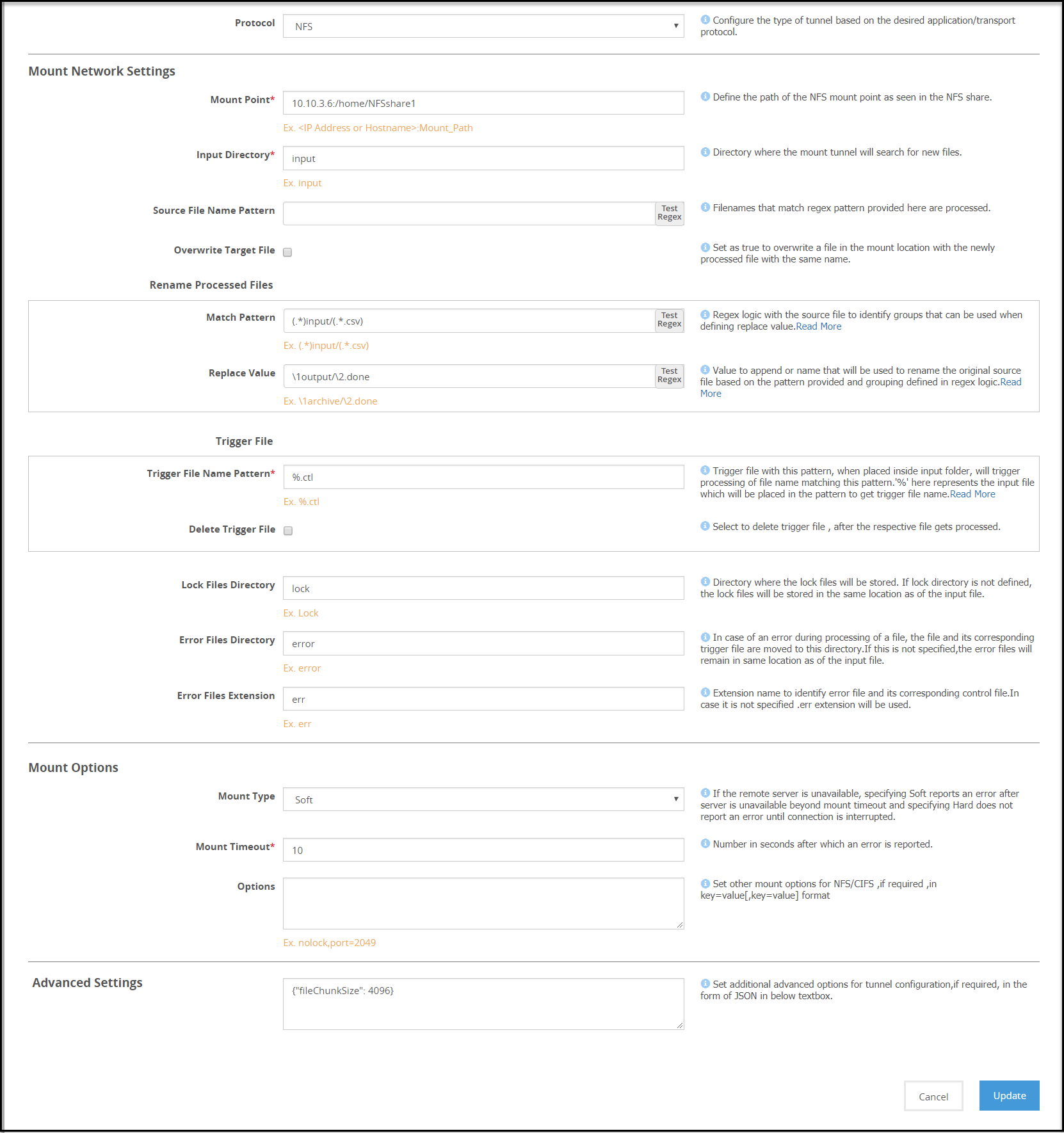
Note: The Address format for an NFS tunnel is
<ip address/hostname>:<mount_path>and for a CIFS tunnel is\\<ip address or hostname>\<share_path>.
Consider an example NFS/CIFS server with folder structure that includes folders namely, /input, /output, and /lock. When a client accesses the NFS/CIFS server, the files are stored in the input folder. The Mounted File System Out-of-Band Service is used to perform data security operation on the files in the /input folder. A source file is processed only when a corresponding trigger file is created and found in the /input folder.
Note: Ensure that the trigger file time stamp is greater than or equal to the source file time stamp.
After the rules are executed, the processed files can be stored in a separate folder, such as in this example, /output. When DSG nodes poll NFS/CIFS server for a file uploaded, whichever node accesses the file first places a lock on the file. You can specify if the lock files must be stored in a separate bucket, such as /lock or under the source folder. If the file is locked, the other DSG nodes will stop trying to access the file.
If the data operation on a locked file fails, the lock file can be viewed for detailed log and error information. The lock files are automatically deleted if the processing completes successfully.
13.3.1.6.1 - NFS/CIFS
The options for the NFS tunnel as illustrated in the following figure

Mount settings
1 Mount Point - The Address format for an NFS tunnel is <IP address/hostname>:<mount_path>
2 Input Directory - The mount tunnel forwards the files present in this directory for further processing. This directory structure will be defined in the NFS/CIFS share.
3 Source File Name Pattern - Regex logic for identifying the source files that must be processed.
4 Overwrite Target File - Select to overwrite a file in the bucket with the newly processed file with the same name.
Rename processed files
Regex logic for renaming original source files after processed files are generated
5 Match Pattern - Exact pattern to match and filter the file.
6 Replace Value - Value to append or name that will be used to rename the original source file based on the pattern provided and grouping defined in regex logic.
Trigger File
File that triggers the rule. The rule will be triggered, only if this file is found to exist in the input directory. Files in the NFS/CIFS Share directory are not processed until the trigger criteria is met. Ensure that the trigger file is sent only after the files that need to be processed are placed in the source directory. After the trigger file is placed, you must touch the trigger file.
7 Trigger File Name Pattern - Identifier that will be appended to each source file to create a trigger control file. Consider a source file abc.csv, if you define the identifier as %.ctl, you must create a trigger file abc.csv.ctl to ensure that the source file is processed.
It is mandatory to provide a trigger file for each source file to ensure that it is processed. Files without a corresponding trigger file will not be processed.
The *, [, and ] characters are not accepted as part of the trigger file pattern.
8 Delete Trigger File - Enable to delete the trigger file after the source file is processed.
9 Lock Files Directory - Directory where the lock files will be stored. If this value is not provided as per the directory structure in the NFS/CIFS share, then the lock files will be stored in the mount point. Ensure that the lock directory name does not include spaces. The DSG will not process files under the lock directory that includes spaces.
10 Error Files directory - Files that fail to process are moved to this directory. The lock files generated for such files are also moved to this directory.
For example, the file is moved from the /input directory to the /error directory.
11 Error Files Extension - Extension that will be appended to each error file. If you do not specify an extension, then the .err extension will be used.
Mount Options
Parameters that will be used to mount the share.
12 Mount Type - Specify Soft if you want the mount point to report an error, if the server is unreachable after wait time crosses the Mount Timeout value. If you select Hard, ensure that the Interrupt Timeout checkbox is selected.
13 Mount Timeout - Number in seconds after which an error is reported. Default value is 60.
14 Options - Additional NFS options that can be provided as inbound settings. If the lock directory is not defined, then the lock files are automatically placed in the /input directory. For example, {"port":1234, "nolock" "nfsvers": 3}. To enable enhanced security for the mounted share, it is recommended that the following options are set:
noexec,nosuid,nodev
where:
- noexec: Disallow execution of executable binaries on the mounted file system.
- nosuid: Disallow creation of set user id files on the file system.
- nodev: Disallow mounting of special devices, such as, USB, printers, etc.
15 Advanced Settings - Set additional advanced options for tunnel configuration, if required, in the form of JSON in the Advanced Settings textbox. For example, {"interval":5, "fileChunkSize": 4096}. In a scenario where an ESA and two DSG nodes are in a cluster, by using the Selective Tunnel Loading functionality, you can load specific tunnel configurations on specific DSG nodes.
Note: Ensure that the NFS share options are configured in the exports configuration file for each mount that the DSG will access. The all_squash option must be set to specify the anonuid and anongid with the user ID and group ID of the non-root user respectively.
This prevents the DSG from changing user and group permissions of the mount directories on the NFS server.
13.3.2 - Certificates/Key Material
This tab displays key material and other files in three different subtabs.
The Certificates/Key Material tab and subtabs are illustrated in the following figure.

The following table describes the available subtabs:
| Callout | Column/Textbox | Description |
|---|---|---|
| 1 | Certificates | View self-generated or trusted certificates. |
| 2 | Keys | View paired keys associated with certificates and unpaired keys. |
| 3 | Other Files | View other files such as GPG data, etc. |
| 4 | Upload | Upload a certificate, key, or other files. |
The following subtabs are available:
Certificates
Keys
Other Files
13.3.2.1 - Certificates Tab
The certificates uploaded to DSG are displayed in this section. Other information such as paired key, validity, and last modified date is also displayed.
A certificate and key that is paired displays a (![]() ) icon indicating that the certificate is ready to use. A certificate or key without any pairing is indicated with a (
) icon indicating that the certificate is ready to use. A certificate or key without any pairing is indicated with a ( ![]() ) icon. If a certificate or key has expired, it is indicated with a (
) icon. If a certificate or key has expired, it is indicated with a (![]() ) icon. Files available in the Other Files subtab will always be marked with a (
) icon. Files available in the Other Files subtab will always be marked with a ( ![]() ) icon.
) icon.
The Cloud Gateway Certificate Expiration Check scheduled task is created by default to alert about certificates that are due to expire in the next 30 days.
Before you regenerate any default expired certificates, ensure that the best practices for certificates and keys are noted.
The Certificates subtab is shown in the following figure.
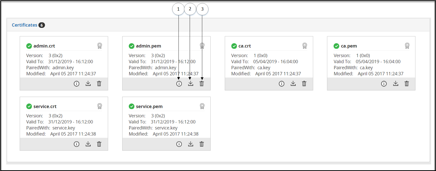
The following table describes the available options:
| Callout | Icon (if any) | Column/Textbox | Description |
|---|---|---|---|
| 1 | Information | View Certificate details. | |
| 2 | Download | Download a certificate. | |
| 3 | Delete | Delete a Certificate. |
13.3.2.2 - Delete Certificates and Keys
Clikc the Delete option in the Certificates/Key Material tab.
The Delete Certificate screen is shown in the following figure:

The following tables describes the available options:
| Callout | Column/Textbox/Button | Description |
|---|---|---|
| 1 | Cancel | Cancel the process of deleting a certificate |
| 2 | Delete | Delete the certificate, key, or other files. |
13.3.2.3 - Keys Subtab
Keys cannot be downloaded, but the information can be viewed (![]() ) or a key can be deleted (
) or a key can be deleted (![]() ).
).
A certificate and key that is paired displays a (![]() ) icon indicating that the certificate is ready to use. A certificate or key without any pairing is indicated with a (
) icon indicating that the certificate is ready to use. A certificate or key without any pairing is indicated with a ( ![]() ) icon. If a certificate or key has expired, then it is indicated with a (
) icon. If a certificate or key has expired, then it is indicated with a (![]() ) icon. Files available in the Other Files subtab will always be marked with a (
) icon. Files available in the Other Files subtab will always be marked with a ( ![]() ) icon.
) icon.
The supported key formats that can be uploaded are .crt, .csr, .key, .gpg, .pub, and .pem. For any private key without an extension, when you click Deploy to All Nodes, the permissions for the key changes to 755 making it world readable. To restrict the permissions, ensure that you generate the key with the .key extension.
The keys uploaded to the DSG can either be a non-encrypted private key or an encrypted private key. For either of the key types uploaded, the DSG ensures that the keys in the DSG ecosystem are always present in an encrypted format. When a non-encrypted private key is uploaded to the DSG, you are presented with an option to encrypt the key. If you choose to encrypt the key, DSG requests for a password for encrypting the key before it is stored on the DSG.
It is recommended that any non-encrypted private key is encrypted before it is uploaded to the DSG. Also,
It is recommended that any key uploaded to the DSG is of RSA type and a minimum of 3072-bits for optimum security.
13.3.2.4 - Other Files Subtab
A certificate and key that is paired displays a (![]() ) icon indicating that the certificate is ready to use. A certificate or key without any pairing is indicated with a (
) icon indicating that the certificate is ready to use. A certificate or key without any pairing is indicated with a ( ![]() ) icon. If a certificate or key has expired, it is indicated with a (
) icon. If a certificate or key has expired, it is indicated with a (![]() ) icon. Files available in the Other Files subtab will always be marked with a (
) icon. Files available in the Other Files subtab will always be marked with a ( ![]() ) icon.
) icon.

The following table describes the available subtabs:
| Callout | Icon (if any) | Column/Textbox | Description |
|---|---|---|---|
| 1 | Information | View Certificate details. | |
| 2 | Download | Download a certificate. | |
| 3 | Delete | Delete a Certificate. |
13.3.2.5 - Upload Certificate/Keys
Click Upload option in the Certificates tab to upload the certificate.
After clicking Upload Certificate, you can either upload a key or a certificate. When you upload a certificate, the password field does not appear.
After you click Choose File to select the key file, you must click Upload Certificate. Enter the password, and then click Upload Certificate again.
It is recommended that the upload of any certificate or key is performed on the ESA. If the certificate is uploaded to a DSG node and a configuration is deployed from ESA, then the changes made on the DSG node are overwritten by the configuration pushed by the ESA.
Note: Ensure that the passphrase for any key that is uploaded to the DSG Web UI is of minimum 8 character length.
If the key you uploaded is an encrypted private key, then you must enter the password for the key.
If the key you uploaded is a non-encrypted private key, an option is presented to encrypt the private key. If you select the option, you must provide a password that the DSG uses to encrypt the non-encrypted private key before it is stored internally.
The following figure illustrates the Upload Cerficate/Key screen

The following table describes the available options:
| Callout | Column/Textbox/Button | Description | Notes |
|---|---|---|---|
| 1 | Choose File | Select certificate and key files to upload. | You cannot upload multiple files in an instance. You must first upload the certificate file, and then the paired .key file. If you upload unpaired keys or certificates, then they are not displayed on the Certificate screen. |
| 2* | Do you want to encrypt the private key | Select the check box to encrypt a non-encrypted private key. If you clear the check box, then the private key will be uploaded without encryption. | It is recommended that any non-encrypted private is encrypted when uploaded to the DSG. |
| 3* | Password | Enter the password for an encrypted private key. For a non-encrypted private key, provide a password that will be used to encrypt the key. | The DSG supports ASCII passwords for keys. If your private key is encrypted with any other character password, then ensure that it is changed to an ASCII password. |
| 4* | Confirm Password | Re-enter the password | |
| 5 | Upload Certificate | Upload the certificate or .key file. | If you upload a private key without an extension, then ensure that you append the .key extension to the key. |
*-Appears only when a key is uploaded.
13.4 - Global Settings
The Global Settings page provides the ability to configure debug options, global protocol settings, and Web UI settings that impact the DSG.
The following image illustrates the UI options on the Global Settings tab.

The following table provides the description for each of the available RuleSet options:
| Callout | Icon | Column/Textbox/Button | Description | Notes |
|---|---|---|---|---|
| 1 | Deploy to All Nodes | Deploy the configurations to all the DSG nodes in the cluster. Note: Deploy can also be performed from the Cluster tab. | In a scenario where an ESA and two DSG nodes are in a cluster, by using the Selective Tunnel Loading functionality, you can load specific tunnel configurations on specific DSG nodes. Click Deploy to All Nodes to push specific tunnel configurations from an ESA to specific DSG nodes in a cluster. | |
| 2 | Expand | Expand the subtab and view available options. | ||
| 3 | Collapse | Collapse the subtab to hide the available options. | ||
| 4 | Edit | Edit the available options in the subtab. |
13.4.1 - Debug
The following figure illustrates the Debug tab.

The following table provides information about fields in the Debug tab.
| Sub tab | Fields | Description |
|---|---|---|
| Log Settings | Log Level | Set the logging level at the node level. |
| Admin Interface | Listening Address | Listening address for the admin tunnel. The DSG listens for requests such as learn mode settings that are sent through the admin tunnel. |
| Admin tunnel is a system tunnel that lets you send administrative requests to individual DSG nodes. | ||
| Listening Port | Listening port for the admin tunnel. | |
| SSL Certificate | The DSG admin certificate to authenticate inbound requests. | |
| SSL Certificate Key | Paired DSG admin key used with the admin certificate. | |
| Client CA Certificate | The .pem file against which the client certificate will be validated. | |
| Client Certificate | Client certificate (.pem) file that is required for establishing communication between the ESA-DSG nodes and the DSG-DSG nodes. | |
| Client Certificate Key File | Paired client certificate key. | |
| Common Name | Common name defined in the client certificate. Ensure that the Common Name (CN) defined in the client certificate matches the name defined in this field. | |
| OpenSSL Cipher Lists | Semi-colon separated list of Ciphers. | |
| SSL Options | Options you must set for successful communication between the ESA-DSG nodes and the DSG-DSG nodes. | |
| Stats Log Settings | Stats Logging Enabled | Enable stats logging to get information about the connections established and closed for any service on all or individual DSG nodes in a cluster. |
| Global Learn Mode Settings* | Enabled | Select to enable Learn Mode at node level. |
| Exclude Payload Types | Resources matching this regex patterns are excluded from the Learn Mode logging. | |
| Exclude Content-Type | Protocol messages with Content-type headers are excluded from the Learn Mode logging. | |
| Include Resource | Resources matching this regex pattern are included in the Learn Mode logging. | |
| Include Content-Type | Protocol messages with Content-type headers are included in the Learn Mode logging. | |
| Free Disk Space Threshold | Minimum free disk space required so that Learn Mode feature remains enabled. The feature is automatically disabled, if free disk space falls below this threshold. You must enable this feature manually, if it has been disabled. | |
| Long Running Routines Tracing | Enabled | Enable stack trace for processes that exceed the defined timeout. |
| Timeout | Define value in seconds to log a stack trace of processes that do not process smoothly in a given timeout. The default value is 20 seconds. |
* - Settings provided in these fields can be overwritten by the settings provided at Service/Ruleset level.
13.4.2 - Global Protocol Stack
The following figure illustrates the Global Protocol Stack tab.

The following table provides information about the fields in the Global Protocol Stack tab.
| Sub tab | Fields | Description | Default | Notes |
|---|---|---|---|---|
| HTTP | Max Clients | If the user wants to increase the number of simultaneous outbound connections that the DSG can create, to serve the incoming requests, then the user can modify this setting. | The default value for this setting is 100. | |
| User defined server header | If you want to change the value of the server header in an application response, then you can use this parameter. | |||
| Outbound Connection Cache TTL | In situations where you want to keep a TCP connection persistent beyond the default limit of inactivity that the firewall allows, you must configure this setting to a timeout value.The timeout value must be defined in seconds. | -1 This value indicates that the feature is disabled. The connection remains active and stored in cache until the DSG node is restarted. | ||
| NFS | Enabled | Set as true to enable the NFS tunnel and service. | ||
| Interval | Time in seconds when the DSG node will poll the NFS server for fetching files. You can also specify a cron job expression. For more information about how to schedule cron jobs, refer to the cron documentation. | The Cron job format is also supported to schedule jobs. If you use the cron job expression “* * * * *”, then the DSG will poll the NFS server at the minimum interval of one minute. |
13.4.3 - Web UI
The following figure illustrates the Web UI tab.

The following table provides information about fields in the Web UI tab.
| Sub tab | Fields | Description | Default |
|---|---|---|---|
| Learn Mode UI Performance Settings | Max Worker Threads | Maximum worker threads that would render learnmode flow dumps on screen. | 15 |
| Flow Dump Filesize | The rules displayed in the Learn mode screen and the payload message difference are stored in a separate file in DSG. If the payloads and rules in your configuration are high in volume, you can configure this file size. | 10 MB |
13.5 - Tokenization Portal
After you set up a cluster between the ESA and multiple DSG nodes, the policies are deployed on respective DSG nodes. Each policy has related data elements, data stores, and roles. You can use the Tokenization Portal menu to examine protection or unprotection of data when a protection data element is used.
The Tokenization Portal provides an interface where you can select the data security operation you want to perform, along with the DSG node, data elements available in the policies deployed at that node, and an external IV value. Every protection operation performed through the Tokenization Portal is recorded as an event in Forensics.
To access the test utilities, in the browser, enter (https://ESA_IP/3.3.0.1.x/1/TokenizationPortal).
Before you access the Tokenization Portal, ensure that the following pre-requisites are met:
- Ensure that any user who wants to access the test utilities must be granted the Cloud Gateway Admin and Policy User permissions.
- Ensure that the ESA where you are accessing Tokenization Portal is a part of the cluster.
- Ensure that the policy on the ESA is deployed to all the DSG nodes in the cluster.
- Ensure that the policy is synchronized across all the ESAs in the cluster.
The following image illustrates the UI options on the Tokenization Portal tab.

The following table provides the description for each of the available Tokenization tab options:
| Callout | Column/Textbox/Button | Sub-Columns | Description | Notes |
|---|---|---|---|---|
| 1 | Input Text | Enter the data you want to protect or unprotect. | ||
| 2 | Output Text | Transformed data, either protected or unprotected based on operation selected. | ||
| 3 | Output Encoding* | Select the type of encoding you want to use. Though the Output Encoding option is part of the Input Text area, remember that encoding is applied to Input data during protection and reprotection, and output data during unprotection. | ||
| 4 | Clear | Clear the text in the Input Text or Output Text box. | ||
| 5 | Unprotect/Protect/Reprotect | Click to perform security operation on the Input Text. You can either Protect, Unprotect, or Reprotect Data. | This option changes to Protect, Unprotect, or Reprotect based on the Action selected for data security operation. | |
| 6 | Clear | Clear the text in the Input Text or Output Text box. | ||
| Action Logs | Logs related to the data protection or unprotection are displayed under this area. These logs are cached in the browser session and are not persisted in the system. | |||
| 7 | Status | Displays | ||
| 8 | DateTime | Date and time when the data security operation was performed. | ||
| 9 | External IV | External IV value that was used for the data security operation. | ||
| 10 | Data Element | Data element used. | ||
| 11 | DSG Node | The DSG node where the data security operation was performed. | ||
| 12 | Output | Transformed data. | ||
| 13 | Input | Input data. | ||
| 14 | Action | Data security operation performed. | ||
| 15 | New External IV | New external IV value that will be used along with the protect or unprotect algorithm to create more secure encrypted data. | This field applies to the Reprotect option only. | |
| 16 | New Data Element | New data element that will be used to perform data security operation. | This field applies to Rthe eprotect option only. | |
| 17 | External IV | External IV value that will be used along with the protect or unprotect algorithm to create more secure encrypted data. | ||
| 18 | Data Element | Data element that will be used to perform data security operation. | ||
| 19 | DSG Node | The DSG node where the data security operation will be performed. | ||
| 20 | Action | Data security operation, Protect, Unprotect, or Reprotect that you want to perform. |
* - The available encoding options are as follows:
- Output Encoding: The field appears when action selected is either Protect or Reprotect.
- Input Encoding: The field appears when action selected is Unprotect.
14 - Overview of Sub Clustering
In a TAC where ESA and DSGs are setup, the configuration files are pushed from the ESA to the DSG nodes on the cluster. However, in versions prior to DSG 3.0.0.0, only a single copy of the gateway configurations could be pushed to the DSG nodes. The ability to push specific rulesets to specific nodes in the cluster was unavailable. From v3.0.0.0, this limitation has been eliminated by introducing the sub-clustering feature.
Sub-clustering allows the user to create separate clusters of the DSG nodes in a TAC. All the nodes in the sub-cluster contain the same rulesets. This enables the user to maintain different copies of rulesets for different sub-clusters. Sub-clusters can be used to define various Lines-of-Business (LOB) of the organization. The user can then create logical node groups to deploy the rulesets on different DSG nodes (LOBs) successfully.
For example, if an XYZ company is spread across the globe with multiple LOBs, then they can use the sub-clustering feature to deploy the configurations to a particular node group, i.e. LOB1, LOB2, LOB3, and so on.
The following image illustrates how the sub-clustering feature is implemented for the DSG nodes.

The figure depicts three node groups LOB1, LOB2, LOB3. Consider LOB1, that caters to only HTTP and S3 services. The common is the service that is shared among all the LOBs. This common service includes the protection profiles, unprotection profiles, and so on, that can be used by the user. Only the tunnels that are used for the required services will be enabled. The other tunnels will not be enabled. Thus, for LOB1, only the HTTP and S3 tunnels will be enabled.
Perform the following steps to push the configurations to the LOB1 node group.
Add four DSG nodes from the cluster page and set the node group as LOB1.
For more information about adding a node and node group to the cluster, refer to the section Adding a Node to the Cluster.Enable the Office 365 and S3 service1 services. These services will be pushed to the LOB1 node group. Disable the NFS service 1, SFTP service, restapi, Adlabs, salesforce, and S3 service 2 services
Select LOB1 to push the rulesets to all the four DSG nodes in the LOB1 node group.
For more information about deploying the configurations to node groups, refer to the section Deploying the Configurations to Node Groups.
The following figure describes a sample use case for sub-clustering.

As shown in the figure, consider LOB1, LOB2, and LOB3 are different lines of business that belong to an XYZ company. Each LOB are as follows:
- The LOB1 will use the S3 bucket’s folder 1 and office 365 SaaS services. This LOB is assigned to nodes D1, D2, D3, and D4.
- The LOB2 will use the Salesforce SaaS, SFTP server, and Adlabs Saas services. This LOB is assigned to nodes D5, D6, D7, and D8.
- The LOB3 will use the NFS share and S3 bucket’s folder 2 services. This LOB is assigned to nodes D9, D10, D11, and D12.
All other services in the RuleSet page will be disabled to deploy the configurations to LOB1 node group.
Important Notes
The sub-clustering feature can only be used when the DSG node is added from the Cluster screen of the DSG Web UI. It is recommended to add the node to the cluster only from this screen. While adding a node, a node group can be assigned to the DSG node. If a node group is not assigned, then a default node group is assigned to that DSG node.
For more information about adding the DSG node from cluster page, refer to the section Adding a Node to the Cluster.The tunnels, certificates/keys, and gateway configuration files are common to all the DSGs in the cluster.
If the user is using the Selective Tunnel Reloading feature with sub-clustering, then ensure that you prefix dsg_ in the node group name while setting the tunnel configuration.
For DSG Appliances, rulesets are deployed based on the node groups that are mapped to it.
For DSG containers, the user can use CoP export API to export the configurations for a particular node group and then deploy it to the containers. This is achieved by passing the Node Group as a parameter to the export API.
For more information about CoP export API, refer to the section API for Exporting the CoP.
Sub-Clustering FAQs
| Questions | Answers |
|---|---|
| What if I have to change the node group assigned to a DSG node? | If you have to change the node group of a node, then login to the ESA Web UI, navigate to Cloud Gateway > {DSG nversion} > Cluster, then on the node click the Actions drop down list and select Change Groups option. Specify the required node group name and save it. |
| What if I have to change the node group on multiple DSG nodes at a time? | If you have to change the node group of multiple DSG nodes at a time, then login to the ESA Web UI, navigate to **Cloud Gateway > {DSG nversion} > Cluster, then select the check box given for a individual node on which the node group must be changed, click the Actions drop down list, and select Change Groups on Selected Nodes option. Specify the node group name and save the changes. |
| From where should be the DSG nodes added to the cluster? | The DSG node must be only added from the Cluster page. Login to ESA Web UI, navigate to Cloud Gateway > {DSG nversion} > Cluster, click Actions drop down list and select Add Node option. For more information about adding a node to the cluster, refer to the section Adding a DSG Node. |
| What if while adding a node to cluster, the deployment node group is not specified? | If the deployment node group is not specified, then by default it will get assigned to the default node group. |
| Can the DSG node be assigned to different node groups at a time? | No, the DSG node can be assigned to only one node group at a time. If required, then you can change the node group but at a time the node will be associated to one node group. |
| What would happen if you add the DSG node from the CLI or TAC? | It is not recommended to add the DSG node from the CLI or TAC. The sub-clustering feature would not work with all the functionalities. |
| Can we deploy the configurations to multiple node groups? | Yes, if you have different node groups and you click Deploy to Node Groups option on the Cluster tab or Ruleset screen then it will show all the node groups created. Select the check box of the node groups to which the configurations must be pushed. |
| How to configure the services in the Ruleset page, to push it to a particular node group? | Enable the required services and deploy it to the intended node group. Note: Disable all the services that are not intended to be pushed on the node group. |
| Can I have separate node groups as LOB1, lob1, or any combination of letters for this node group name? | All the combination of letters of the node group name is considered as same and it will be displayed in the lowercase. |
| Can we deploy the configuration to the node group without providing the tag name or description? | Yes, the tag name and description are not the mandatory fields. If you do not provide the tag name, then the configuration version will be untagged. |
| What would happen if the node group has a recently deployed configuration and you are assigning that node group to a DSG node? | In this scenario, the recently deployed configuration for that node group will be redeployed to the DSG node. |
15 - Implementation
This section describes the post configuration steps involved in implementing the DSG, including RuleSets Configuration, Migration, Testing and Production Rollout.
The configuration of a Ruleset will be subject to the data being processed and how the data is exchanged between the systems interacting with the DSG. A common SaaS deployment example is utilized for clarification and additional generic examples, where applicable, are provided.
The process involves the following steps:
Network Setup
- Domain Name System (DNS)
- Connectivity
- Upload or generate SSL Certificates
- Configure Tunnels
Configuring Ruleset
- Create a Service under Ruleset
- Use Learn Mode to find message carrying sensitive data
- Create a Profile under Service and define rules to intercept the message and transform it
Optional: Forwarding logs to external SIEM systems
Rolling Out to Production
This section will continue to follow the prototypical organization, Biloxi Corp, an enterprise that chose to protect a SaaS called ffcrm.com. The crm.example.com example follows to demonstrate the configuration of the Ruleset profile.
Network Setup
As part of setting up the CRM, you must set up domain names and ssl certificates.
Domain Name System
The CRM SaaS selected by Biloxi Corp is accessible through the public domain name www.ffcrm.com. To integrate the gateway in front of the CRM, the consumers need to be directed to the gateway’s load balancer. A public domain like www.ffcrm.com is owned by a third party. So, the necessary changes must be made to the DNS to point to the DSG’s load balancer. Therefore, a domain name, www.ffcrm.biloxi.com, is used to internally represent the external www.ffcrm.com address. DNS would then be configured such that all sub domain names (i.e. www.ffcrm.biloxi.com or anything.ffcrm.biloxi.com) will always point to the same DSG’s load balancer address.
The public domain name www.ffcrm.com will be accessible to Biloxi Corp users. However, that concern is addressed by preventing them from successfully authenticating with the service should they attempt to bypass the gateway, intentionally or by error.
In a lab or testing environment, one can alternatively modify their local system hosts file to achieve a similar goal. This approach only effects the local machine and does not support wild card configuration, hence each domain name must be specified explicitly.
For example: 2.10.1.53 ffcrm.biloxi.com www.ffcrm.biloxi.com
This part is completed when all SaaS domain names resolve to your gateway’s load balancer IP address.
Network Connectivity
Biloxi Corp is following network segregation best practices using network firewalls. Thus, communication between systems in different parts of the network is strictly controlled.
Depending on where the gateway is installed, some of the firewall’s configuration must be modified so that the gateway cluster is reachable and accessible. The public domain www.ffcrm.com must also be accessible to the gateway cluster.
Administrative web interface and ssh access to ESA and the DSG cluster may require adjusting network firewall settings.
Verify that the network is properly configured to allow connectivity to the DSG cluster. This can be validated using tools like ping and telnet. In addition, you’ll need to confirm the connectivity between the gateway nodes themselves and the public SaaS system.
SSL Certificates
The load balancer in front of the DSG cluster at Biloxi Corp is equipped with the appropriate SSL Certificate. However, another certificate needs to be generated to secure the connectivity between the load balancer and the gateway cluster. The certificate can be generated using standard SSL processes and then made available to the DSG along with its key using the upload button.

Configuring Ruleset
This section explains steps to create rules and how the rule trajectory can be tracked with Learn Mode.
Creating a Service under RuleSet
At this point it is not known how sensitive data is exchanged with the CRM application. To find out the details, the Learn mode functionality is used, which is controlled at the Service level. Before you begin creating services, ensure that you read the Best Practices for defining services. For more information about best practices, refer to Best practices
Using the main menu, navigate to Cloud Gateway > 3.3.0.0 {build number} > RuleSet > RuleSet. Click the Add New Service link to create a new service. After giving it an appropriate name and description, the new HTTP Gateway Service needs to be associated with one or more tunnels. Through these tunnels the www.ffcrm.com application network message exchange will be occur. Use the (+) icon next to the Tunnels and Host Addresses fields to associate the service with the default_443 HTTPS tunnel, the internal hostname to be utilized (www.ffcrm.biloxi.com), and the original SaaS URL (www.ffcrm.com) for the Forwarding Address entry.

The hostname is how DSG identifies which service applies to an incoming message.
The transaction metric logging feature available at the service level provides a detailed metrics of the transactions occuring in DSG. These details can be logged as part of the gateway.log whenever a protect operation HTTP request is made to the DSG. For more information about transaction metrics options, refer to Transaction Metrics logging.
The sample metrics as seen in the log file are as follows:

Restart the gateway cluster for this change to take effect.
Trusting Self-Signed Certificates for an Outbound Communication
Learn-mode is used to analyze the payload carrying sensitive data, examine its structure, and design rules to protect the sensitive data in the payload before it is forwarded on to www.ffcrm.com. For TLS-based outbound communications in the DSG, it is expected that the server or SaaS uses a certificate that is signed by a trusted certification authority. In some cases, self-signed certificates are used for outbound communications. For such cases, the DSG is required to trust the outbound server’s certificate to enable TLS-based outbound communications.
Perform the following steps to trust self-signed certificates in the ESA node.
In the ESA Web UI, navigate to Settings > System > File Upload.
Click Browse to upload the self-signed certificates.
From the ESA CLI Manager, navigate to Administration > OS Console. Ensure that the certificate is in PEM (ASCII BASE64) format. This may be done by inspecting the certificate file using the cat command to verify whether the contents of the certificate are in readable (BASE64 encoded) or in a binary format.
If the contents of the certificate are in binary format (DER), execute the following command to convert the contents to PEM (BASE64 encoding), else proceed to Step 7.
openssl x509 -inform der -in <certificate name>.cer -out <certificate name>.pemCreate a directory
opt/protegrity/alliance/config/outbound_certs/ if it does not exist.Create a file trusted.cer under
/opt/protegrity/alliance/config/outbound_certsif it does not exist.Copy the contents of the Base64 converted certificate (.pem) file to the trusted.cer file.
cat <certificate name>.pem >>
opt/protegrity/alliance/config/outbound_certs/trusted.cer
If you started with a different certificate file extension name that was already ASCII Base64 encoded, then use the same extension name instead of the “.pem” file extension name in the command example above.
In the ESA Web UI, navigate to Cloud Gateway > 3.3.0.0 {build number} > RuleSet.
Select the service to which the certificate is assigned and click Edit.
Add the following option in the Outbound Transport Settings textbox.
{"ca_certs": "/opt/protegrity/alliance/config/outbound_certs/trusted.cer"}Restart the Cluster by navigating to Cloud Gateway > 3.3.0.0 {build number} > Cluster to replicate certificates to all DSG nodes.
Use Learn Mode to find message carrying sensitive data
When enabled, Learn mode logs all messages exchanged with the host names entries matching the service configuration. This allows us to analyze the payload to learn its structure so appropriate rules can be set to transform the relevant parts in it before it is forwarded on.
Let’s first check that Learn mode is functioning properly by verifying that new entries are shown as the www.ffcrm.biloxi.com application is accessed. Navigate the main menu Cloud Gateway > 3.3.0.0 {build number} > RuleSet > Learn Mode. If this is the first time you’re visiting the Learn mode page then chances are it will come up with no data. You can always click the Purge ( ![]() ) icon to purge the learn mode data.
) icon to purge the learn mode data.
 Navigating to the
 www.ffcrm.biloxi.com application home page will generate new entries in the Learn mode page. It is recommended to use a separate window so that going back to the Learn mode page becomes easier.

Switch back to the Learn page and refresh the list by clicking the refresh (![]() ) icon. New entries will indicate that Learn mode is functioning as expected.
) icon. New entries will indicate that Learn mode is functioning as expected.

Password Masking
The www.ffcrm.biloxi.com application requires users to authenticate with their username and password before they can use the application. To avoid Learn mode from logging user’s passwords, Service’ Password Masking needs to be configured. The Password Masking configuration comprised of a regex pattern to identify the URL(s), another regex pattern to identify the password in the payload and a masking value which will replace the password before the message is logged by Learn mode.
To do that, the request message carrying the password needs to be identified when the authentication is submitted. Using a unique value for the password will make it easier to find in Learn mode. No need to use real username and password, instead let’s use testusertest for the username and testpasswordtest for the password.

Submit the login form, switch to the Learn mode screen and refresh it.

Additional messages now appear in the list. Let’s examine the first entry listed right after submitting the fake credentials by clicking on it. Additional details will appear at the bottom of the page. Click any entry on the left, select the Messages Difference tab on the right to see the message payload and scroll all the way down.

The rules displayed in the Learn mode screen and the payload message difference are stored in a separate file in DSG. The default file size limit for this file is 3MB. If the payloads and rules in your configuration are high in volume, you can configure this file size.
In the ESA CLI Manager, navigate to Administration > OS Console. Edit the webuiConfig.json file in the /opt/protegrity/alliance/config/webinterface directory to add the Learn mode file size parameter as follows:
{
"learnMode": {
"MAX_WORKER_THREADS": 5,
"LEARNMODE_FLOW_DUMP_FILESIZE": 10
}
}
You can now see that the characteristics of the message carrying the authentication password can be the request message Method and URL. It can be concluded that the authentication with www.ffcrm.com is handled by a POST request to /authentication URI . The password is carried in this message body as a value for the parameter name authentication%5Bpassword%5D . This is URI/www-form encoding for authentication[password].
In some cases, you may need to repeat this test several times to confirm the consistency of the URL, parameter names, etc.
With these details, adjust the service configuration with the details that were found to mask the authentication password or any other data not required by learn mode to log in the clear. Both the pattern and the resource are regular expressions so let’s use /authentication$ for the resource and (?<=(\bauthentication%5Bpassword%5D=))(.+?)(?=($|&)) for the pattern.

Save the changes and restart the cluster for these changes to take effect. You can do that from the Cloud Gateway > 3.3.0.0 {build number} > Cluster page, Monitoring tab.

Test the change made to the service settings by repeating the authentication attempt as done before. Again, no need to use real credentials, as this step is to ensure the password gets masked in Learn mode.

Note that resetting the Learn mode list makes it easier to find the messages you are looking for in a smaller set of message.
Protecting Sensitive Data
Data protection is achieved by finding the target data in a message and transforming it from its clear state. Then, protect and return it depending on the flow direction of the message. In the www.ffcrm.com application the account names need to be protected So, the gateway will be configured to protect account names in messages transmitting it from user’s browser to the application backend. The gateway will also be configured to unprotect when it is consumed by transforming it in message payloads transmitted from the application backend back to user’s browser.
Following the Protegrity methodology, the discovery phase will uncover all the sensitive data entry points in our target application. One obvious entry point is the page in the application where users can create new accounts. Navigate www.ffcrm.biloxi.com to where new accounts are created and purge the Learn mode list before creating a new testing account. A sample TestAccount123 is unique enough name to easily find in Learn mode.

Switching back to Learn mode page, the message created with the account name TestAccount123 can be found.

Learn mode is showing that DSG sees this information sent as a value to the account[name] parameter in the POST request message body to /accounts URI. The message body is encoded using URL Encoding which is again why account[name] is displayed as account%5Bname%5D.
The details to create a set of rules under Ruleset to extract the posted account name and protect it using Protegrity Data Protection transformation is available. Create a profile under the existing service and call it Account Name.

Now create a new rule which will extract the body of the create account message. This rule will look for a POST HTTP Request message with URI matching the regular expression /accounts$.

Under the Create Account Message rule, let’s add another rule to extract the value of the parameter which carries the account name found earlier that this parameter name is account[name].

Lastly, the account name needs to be protected using a Protegrity Data Protection Transformation rule. This rule requires us to specify and configure how to protect the data. A Data Element is a value defined in data security policies managed by Security Officers using the Protegrity Enterprise Security Administrator (ESA), which represents data security characteristics like encryption or tokenization. Our security officer had provided us with a data element name PTY_ACCOUNT_NAME which was created for protecting account names in Biloxi corp.
The alliance user is an OS user and is responsible for managing DSG processes. Ensure that you do not add this user as a policy user.
In addition to the data protection, an encoding codec with unique prefix and suffix will be used. This allows for the protected data to be easy to find by looking for data which begins and ends with the specified prefix and suffix. This is beneficial when the data is consumed and a set of rules must be created to remove the protection. Instead of creating a rule for every message that might contain the protected account name, we can scan each message returning from www.ffcrm.biloxi.com and unprotect the protected data we find corresponding to our prefix and suffix.

Restart the gateway cluster and test the new set of rules that was created by creating a new account name TestAccount456.
The expected result is that the new account name will appear protected (encrypted/tokenized and encoded).

Lastly, the data protection applied on Account Names needs to be reversed. This allows the authorized Biloxi users consuming this information through www.ffcrm.biloxi.com to see it in the clear.
The prefix and suffix will assist in locating the protected account names in every payload coming back from the application. Therefore, a generic rule for textual payloads can be created. This will look for protected account names and unprotect them such that users will get the HTML payload with the account name in the clear.
The top level branch in this case will target a HTML Response message.

In the extracted HTML Response message body, we will look for the protected account names by searching for values matching a regex pattern comprised of our prefix and suffix.

The leaf rule of this branch will unprotect the extracted protected account names found in the HTML response payload.

Restart the gateway cluster and test the new rules branch created by revisiting the page where TestAccount456 account name appeared protected earlier. A simple refresh of the web page may not be enough as local caching may be used by the browser. Clearing cache, local storage and session information may be required.

Other payload types such as JSON or XML may be used by the application therefore additional generic unprotect rules for these payload types may be required.
Forwarding logs to SIEM systems
You can forward all ESA and gateway logs to an external Security Information and Event Management (SIEM) system, such as Splunk or AWS Cloudwatch.
Forwarding logs to an external SIEM
If you plan to forward all ESA and gateway logs to an external SIEM system, configure the alliance.conf file.
To forward logs to an SIEM system:
In the ESA Web UI, navigate to Settings > System.
Navigate to the Cloud Gateway > 3.3.0.0 {build number} > Settings area.
Click Edit to edit the
alliance.conffile.You can either send all logs to the SIEM system or just the gateway logs.
To send gateway or DSG logs using TCP, add the following rule to the file.
*.* @@(<IP_ADDRESS> or <HOSTNAME>):<PORT>To send gateway or DSG logs using TCP, add the following rule to the file.
:msg, contains, "PCPG:" @@(<IP_ADDRESS> or <HOSTNAME>):<PORT>
Ensure that the rule is the first entry in the alliance.conf file. The configurations must be made in ESA. After you deploy the configuration, ensure that the rsyslog service is restarted on each DSG node. If you are using UDP protocol instead of TCP protocol, the rules to be defined are as follows:
- To send gateway or DSG logs using UDP, add the following rule to the file.
*.* @(<IP_ADDRESS> or <HOSTNAME>):<PORT> - To send gateway or DSG logs using UDP, add the following rule to the file.
:msg, contains, "PCPG:" @(<IP_ADDRESS> or <HOSTNAME>):<PORT>
The following file is a sample alliance.conf file that shows the SIEM configurations.

Forwarding logs to AWS CloudWatch
The AWS CloudWatch must be configured with each DSG node in the cluster to forward the logs from an DSG appliance. After the AWS CloudWatch is configured with a DSG node, you must add the path of the required DSG appliance log files to the appliance.conf file in the appliance.
Rolling Out to Production
Following the Protegrity methodology, production rollout requires deploying the DSG with all the necessary rules to protect and unprotect sensitive data. You also need to prevent users/applications from bypassing the DSG to avoid sensitive data in the clear from reaching the target application directly. Lastly, migrate any historical data that may already exist in the target system.
After a Ruleset is created and tested in a sandbox or testing environment, back up and export the entire configuration and then import and restore it on the production DSG cluster. Addresses, certificates and data element names may be different within the non-production system which may require modifications. Before going live, it is recommended to test and verify the Ruleset configuration for all sensitive data in scope of the workflow mapped during discovery phase. After a successful testing of the workflows, acess the application backend directly to confirm that all sensitive data is protected on the application backend side. No backend instance of the target sensitive data exists in the clear.
The target application may still be accessible directly, especially when the target application is a public SaaS. For example, after production rollout, Biloxi users may still attempt to access www.ffcrm.com directly. The risk in this scenario is that a user has the ability to submit data that has not been protected by the DSG before reaching the application backend. If the application is external, i.e. SaaS, controlling the authentication can be used to solve this problem.
Authentication may be offered by the SaaS provider using SAML or by owning the authentication process themselves. Most organizations would prefer Single Sign On (SSO) using SAML which the DSG can be configured to proxy or resign, essentially establishing a trust between DSG and the SaaS. If SAML is not an available option, DSG can be configured to treat username/password as sensitive data as well. This means that users will be known to the SaaS as their protected username and password. An attempt to bypass the DSG in a way would provide the same error as it would for users who are not known to the application at all.
It is not uncommon to introduce data protection to a system already in use. In such cases, it is likely that data designated for protection has already been added to the system in the clear. Historical data migration is the process of replacing the sensitive data from its clear state to a protected state. Applications may offer different ways of achieving this goal normally by exporting the data, transforming it and importing it back into the system. DSG REST API can be used to perform the transformation which will require a Ruleset to be configured for the exported payload format.
Homegrown and third party application changes all the time and therefore it is highly recommended to maintain a testing environment for future Ruleset or other configuration modification that may be needed.
16 - Transaction Metrics Logging
The transaction metrics allows the user to view the detailed information of the operations performed by the DSG. The Transaction metrics logging feature can be enabled at the service level.
For more information about enabling the transaction metrics logging feature, refer to the Table: Service Fields.
The transaction metrics are logged in the gateway.log file in JSON format.
The sample transaction metrics for a REST request is as seen in the following snippet.
![]()
The following table describes the parameters available in the transaction metrics for different services.
| Parameter | Service Supported | Data Type in DSG | Data Type in the Audit Store | Description | Examples |
|---|---|---|---|---|---|
| auth_cache_hit | HTTP, REST | boolean | boolean | The credential cache status. True indicates that the basic authentication credentials were cached and False indicates that the credentials were not cached. | False |
| auth_end_time | HTTP, REST | string | string | The timestamp when the basic authentication was completed. | 2024-02-28T11:26:17.482491732+00:00 |
| auth_start_time | HTTP, REST | string | string | The timestamp when the basic authentication was started. | 2024-02-28T11:26:17.466345072+00:00 |
| auth_total_time | HTTP, REST | float | double | The difference in seconds between the auth_time_end and auth_time_start parameters. | 0.016147 |
| auth_user_name | HTTP, REST | string | string | The username used for basic authentication. | admin |
| bucket_name | S3 Out-of-Band | string | string | The name of the S3 bucket from where the DSG reads the object to be processed. | dsg-s3/incoming |
| client_correlation_handle | All | string | string | The ID used to uniquely identify a request. It is usually a UUID. This parameter is optional. | 31373039313139363333353837 |
| client_ip | All | string | string | The IP address of the client that sent the request to the DSG. | 192.168.1.10 |
| data_element_name | All | string | string | The name of the data element used to transform the sensitive data. | PTY_Unicode |
| data_protection | All | object | object | The object representing the Protegrity Data Protection transformation rule. | {"data_protection":{"data_elements":[{"data_element_name":"TE_A_N_S13_L1R3_N","num_unprotect":20,"len_unprotect":428}]}} |
| dsg_version | All | string | string | The version number of the gateway process. | 3.1.0.0.103 |
| file_name | S3 Out-of-Band, Mounted Out-ofBand | string | string | The name of the file that has been processed. | Sample_S3.csv |
| http_method | HTTP, REST | string | string | The HTTP method associated with request. | POST |
| http_outbound_available_clients | HTTP | integer | long | The number of outbound HTTP clients available for the requests. | 100 |
| http_outbound_count_new_connections | HTTP | integer | long | The number of new connections created to process the request.
| 1 |
| http_outbound_count_redirect | HTTP | integer | long | The number of redirects encountered while processing a request. | 0 |
| http_outbound_local_port | HTTP | integer | integer | The local port used for the outbound connection. | 60084 |
| http_outbound_response_code | HTTP | integer | integer | The HTTP status response code from downstream system. | 200 |
| http_outbound_size_download | HTTP | float | double | The size of the data received from the downstream system in bytes. | 76.00 |
| http_outbound_size_queue | HTTP | float | double | The number of requests waiting to be sent to downstream systems. | 0 |
| http_outbound_size_upload | HTTP | float | double | The size of data sent to downstream system in bytes. | 76.00 |
| http_outbound_speed_download | HTTP | float | double | Average download speed. Bytes per second. | 4.00 |
| http_outbound_speed_upload | HTTP | float | double | Average upload speed. Bytes per second. | 75697.00 |
| http_outbound_time_appconnect | HTTP | float | double | The time taken to complete the SSH/TLS handshake. | 0.000000000 |
| http_outbound_time_connect | HTTP | float | double | The time taken to connect to the remote host. | 0.000374000 |
| http_outbound_time_namelookup | HTTP | float | double | The time taken to resolve the name. | 0.000161000 |
| http_outbound_time_pretransfer | HTTP | float | double | The time from the start until before the first byte is sent. | 0.000397000 |
| http_outbound_time_queue | HTTP | float | double | The time that the requests spent in the queue before being processed. | 0.000008821 |
| http_outbound_time_request | HTTP | float | double | The time from when the request was popped off the queue to be processed to the time a response was sent back to the caller. | 0.001168013 |
| http_outbound_time_starttransfer | HTTP | float | double | The time taken from the start of the request until the first byte was received from the server. | 0.000398000 |
| http_outbound_time_total | HTTP | float | double | Total time that the client library took to process the HTTP request. | 0.001004000 |
| http_outbound_url | HTTP | string | string | The destination URL used for the outbound request. | http://tornadoserver:8889/passthrough |
| http_reason_phrase | HTTP, REST | string | string | The reason phrase associated with the HTTP status code. | OK |
| http_status_code | HTTP, REST | integer | integer | The HTTP status code sent to the HTTP client. | 200 |
| input_etag | S3 Out-of-Band | string | string | The Etag of the input object processed by the DSG. | a0b00e60cc87fff8537e68827c3f329a |
| input_size | S3 Out-of-Band | integer | long | The size of the input object, in bytes, processed by the DSG. | 81 |
| learn_mode_enabled | All | boolean | boolean | Indicates if the Learn mode is enabled. | false |
| len_protect | All | integer | long | The length of the sensitive data that is protected. | 30 |
| local_port | HTTP, REST | integer | integer | The local port used for the inbound connection, can be used with the open_connections parameter to identify new and unique connections. | 43004 |
| logtype* | All | NA | string | The value to identify type of metric, such as, dsg_metrics_transaction. | dsg_metrics_transaction |
| method | SFTP | string | string | The SFTP method associated with the request. The method can be either GET or PUT. | download |
| node_hostname | All | string | string | The hostname of the DSG. | protegrity-cg123 |
| node_pid | All | integer | integer | The process id of the gateway process that processed the request. | 56532 |
| num_protect | All | integer | long | The number of protect operations performed. | 3 |
| num_replace | All | integer | long | The number of regex replace performed. | 2 |
| open_connections | HTTP, REST | integer | long | The number of open connections associated with the tunnel in a process. | 1 |
| origin_time_utc* | All | NA | date | The time in UTC at which this log is ingested. | Feb 26, 2024 @ 03:51:54.416 |
| output_bucket_name | S3 Out-of-Band | string | string | The name of S3 bucket where the DSG writes the processed object. | dsg-s3/incoming |
| output_etag | S3 Out-of-Band | string | string | Etag of the output object processed by the DSG. | a0b00e60cc87fff8537e68827c3f329a |
| output_file_name | S3 Out-of-Band | string | string | The name of the object that is written to the new S3 bucket (i.e. The value of output_bucket_name parameter) by the DSG. | Sample_s3.csv |
| output_size | S3 Out-of-Band | integer | long | The size of the object, in bytes, written to the output S3 bucket. | 81 |
| processing_time_downstream | HTTP, SMTP, SFTP | float | double | The time is the difference between the start time of processing a response and the end time of processing a request. | 0.003696442 |
| processing_time_request | All | float | double | The time taken for the ruleset to process the request data. | 0.001080275 |
| processing_time_response | HTTP, SMTP, SFTP, S3 Out-of-Band | float | double | The time taken for the ruleset to process the response data. It is only applicable to the protocols where a response is expected from a downstream system. | 0.000162601 |
| regex_replace | All | object | object | The object representing the Regex Replace transformation rule. | {"regex_replace":{"replace_rules":[{"rule_name":"Hello -> HELLO","num_replace":6},{"rule_name":"World -> dlroW","num_replace":6}]}} |
| request_uri | HTTP, REST | string | string | The URI of the request being processed by the DSG. | http://httpservice/passthrough |
| rule_name | All | string | string | The name of the rule used to transform the sensitive data. | Sample Rule1 |
| server_ip | SFTP | string | string | The IP address orhostname of the SFTP server that the DSG is communicating with. | sftp.server.com |
| service_name | All | string | string | The name of the service processing the request. | Passthrough |
| service_type | All | string | string | The type of the service processing the request. | HTTP-GW |
| time_pre_processing | HTTP, REST | float | double | The time an HTTP or REST request waited before it was processed. | 0.010870 |
| time_start | All | date | date | The timestamp when the DSG received a request. | 2024-02-28T11:27:13.515926838+00:00 |
| time_end | All | date | date | The timestamp representing when a request was completed. | 2024-02-28T11:27:13.519971132+00:00 |
| time_lock | S3 Out-of-Band | float | double | The time taken to process the file from the time the lock was created. | 1708963670.43 |
| time_total | All | float | double | The difference, in seconds, between the time_end and time_start parameters. | 0.005429983 |
| transformations | All | object | object | The object representing the Regex Replace and Protegrity Data Protection transformation rules. | "transformations":{"data_protection":{"data_elements":[{"data_element_name":"TE_A_N_S13_L1R3_N","num_unprotect":20,"len_unprotect":428}]}} |
| tunnel_name | All | string | string | The name of the tunnel processing the request. | default_80 |
| user_name | All | string | string | The username used for the protection, unprotection, or reprotection. | jack123 |
* -The origin_time_utc and logtype parameters will only be displayed on the Audit Store Dashboards.
By default, the normalize-time-labels flag is configured in the features.json file. If the normalize-time-labels flag is configured, then it converts the default timestamp parameters to normalized timestamp parameters, as shown in the Table: Default and Normalized timestamp parameters.
To access the features.json file, navigate to Settings > System > Files, and under the Cloud Gateway - Settings area, access the features.json file.
The following table shows the default timestamp parameters and the normalized timestamp parameters.
Default and Normalized timestamp parameters
| Default Timestamp Parameters | Normalized Timestamp Parameters |
|---|---|
| auth_end_time | auth_time_end |
| auth_start_time | auth_time_start |
| auth_total_time | auth_time_total |
| end_time | time_end |
| start_time | time_start |
| total_time | time_total |
| pre_processing_time | time_pre_processing |
Forwarding Transaction Metrics to Audit Store
The transaction metrics are also forwarded to the Audit Store and can be viewed on the Audit Store Dashboards.
Ensure that the following prerequisites are met before you view the logs on the Audit Store Dashboards:
The Analytics component is initialized on the ESA. The initialization of Analytics is required for displaying the Audit Store information on the Audit Store Dashboards.
For more information about initializing Analytics, refer Initializing Analytics on the ESA.
For more information about the audit indexes, refer to the section Understanding the audit index fields.
The logs are forwarded to the Audit Store.
For more information about forwarding the logs, refer to the section Forwarding Audit Logs to Insight.
The following figure shows the sample transaction metrics on the Discover screen of the Audit Store Dashboards.
![]()
Note: The index_node, tiebreaker, and index_time_utc parameters are only logged on the Audit Store Dashboards.
The DSG transaction logs are stored in the pty_insight_analytics_dsg_transaction_metrics_9.2 index file. It is recommended to enable the scheduled task to free up the space used by old index files that you do not require. For transaction metrics, edit the Delete DSG Transaction Indices task and enable the task. The scheduled task can be set to n days based on your preference.
For more information about scheduled tasks, refer to the section Using the scheduler.
Total Time Breakdown for HTTP Request
This section describes the total time taken for processing the HTTP request.
The total_time value is calculated by adding the time taken by the following parameters:
- time_pre_processing: The time an HTTP or REST request waited before it was processed.
- processing_time_request: The time taken for the ruleset to process the request data.
- processing_time_downstream: The time taken to send a request to a downstream system and receive a response from the client.
- processing_time_response: The time taken for the ruleset to process the response data.
The following chart depicts the breakdown of the total time taken for an HTTP request.

The processing_time_downstream value is the difference between the start time of processing the response and the end time of processing a request. The processing_time_dowstream is calculated by considering the time taken by any the following parameters:
- http_outbound_time_queue: The time that the request spent in the queue before being processed.
- http_outbound_namelookup: The time taken to resolve the name.
- http_outbound_time_connect: The time taken to connect to the remote host.
- http_outbound_time_appconnect: The time taken to complete the SSH/TLS handshake.
- http_outbound_time_pretransfer: The time from the start until before the first byte is sent.
- http_outbound_time_starttransfer: The time taken from the start of the request until the first byte was received from the server.
- http_outbound_time_total: Total time that the client library took to process the HTTP request.
- http_outbound_time_redirect: The time, in seconds, it took for all redirection steps including name lookup, connect, pretransfer, and transfer before the final transaction was started.
The following chart depicts the processing time downstream for an HTTP request.

17 - Error Metrics Logging
Error Metrics allow a user to view details about errors, which are encountered while processing a file. The error metrics logging feature can be enabled at the service level.
When the Protegrity Data Protection Transform Rule is configured, certain error conditions can occur during processing. The following are some of the error conditions:
- The input is too short or long for a particular data element
- Invalid Email ID
- Invalid Data Type
- Invalid Credit Card Details
When these error conditions occur, the rule will stop processing. The permissive error handling feature is hence used to handle the errors and process the erroneous input file.
For more information about permissive error handling, refer to the Table: Protegrity Data Protection Method.
If there are a lot of erroneous data in an input file, it can be difficult to identify and categorize errors. In that situation, the error metrics can be used to understand the total number of errors, the offset of where the error was encountered, the reasons why the error was encountered, the ruleset details, and so on.
Error metrics is written to the gateway.log file and the Log Viewer screen in the JSON format.
In the case of NFS and CIFS protocols, a lock file is created for each file that is to be processed. Error metrics will also be appended to the lock files alongside the update details for each file. For example, if there are ten files to be processed, namely, Test1 to Test10, then ten respective lock files will be created, namely, Test1.lock to Test10.lock. If there are any errors encountered in the Test1 file, then the error metrics for this file will be appended to the Test1.lock file.
Important: The error metrics is only supported for the following payloads:
- CSV Payload
- Fixed Width
For more information about the CSV and Fixed Width payloads, refer to the sections CSV Payload and Fixed Width.
Important: The error metrics support is only available for the following services:
- HTTP
- REST
- NFS
- CIFS
Important: The following conditions should be met to use the error metrics logging feature:
- Users must use the Protegrity Data Protection method to transform the data.
- Permissive error handling should be configured at the transform rule.
- Error Metrics Logging field must be enabled at the service level.
Note: If the permissive error handling is disabled or a different transformation method is used, then the total_error_count will be 1 in the error metrics.
The sample error metrics for the REST request is as seen in the following log file snippet:

The following table describes the parameters available in the error metrics for different services.
| Parameter | Services Supported | Data Type in DSG | Data Type in the Audit Store | Description | Example |
| column_info | HTTP, REST, NFS, CIFS | integer, string | integer, string | For the CSV payload, a list of column numbers and column
names will be logged when the errors are encountered.NoteThe
Header will be taken from the CSV or the Fixed Width extract
rule. While configuring the CSV extract rule, if the Header is
set to -1, then the column_info parameter
will not be logged in the error metrics.The following snippets shows the
column_info parameter for the Fixed Width
payload:"column_info": {
"1": {
"column_start": 3,
"column_width": 17
}
}, | {"column_info":{"2":"first_name"} |
| columns | HTTP, REST, NFS, CIFS | integer | long | The column numbers where the error is encountered. | 2 |
| error_count | HTTP, REST, NFS, CIFS | integer | long | The total number of errors encountered for a particular reason. | 1 |
| file_name | NFS, CIFS | string | string | The name of the file that is being processed by the DSG. | Sample_NFS.csv |
| id | HTTP, REST, NFS, CIFS | string | string | A unique ID to identify the transaction. | a272d51b14df435eb67fdf46d2ecff83 |
| logtype* | All | NA | string | The value to identify type of metric such as
dsg_metrics_error. | dsg_metrics_error |
| node_hostname | HTTP, REST, NFS, CIFS | string | string | The hostname of the DSG. | protegrity-cg123 |
| node_pid | HTTP, REST, NFS, CIFS | integer | integer | The Process ID of the gateway process that processed request. | 5577 |
| origin_time_utc* | All | NA | date | The time in UTC at which this log is ingested. | Feb 26, 2024 @ 03:51:54.416 |
| reasons | All | object | object | The object representing the set of error reason, ruleset details, offset of columns or rows, and error count. | reasons":[{"reason":"The input is too short (returnCode 0)","rulesets":[{"ruleset":"CSV Rule","offset":[{"columns":[{"2":{"rows":[2,5,8,11,14,17,20],"trimmed":false}}]}],"error_count":7}]}] |
| reason | HTTP, REST, NFS, CIFS | string | string | The reason for a particular error will be displayed. | The input is too short (returnCode 0) |
| request_uri | HTTP, REST | string | string | The URI of the request being processed by the DSG. | http://testservice:8081/echo |
| rows | HTTP, REST, NFS, CIFS | integer | integer | The row numbers where the error is encountered. | 0 |
| ruleset | HTTP, REST, NFS, CIFS | string | string | The traversal of the transform rule, which induces the error. | Text Protection/Word by word data extraction/Data Protection |
| service_name | HTTP, REST, NFS, CIFS | string | string | The name of the service processing the request. | REST Demo Service |
| time_end | HTTP, REST, NFS, CIFS | string | date | The timestamp representing when a request was completed. | 2024-02-28T11:48:26.318685532+00:00 |
| total_error_count | HTTP, REST, NFS, CIFS | integer | long | The total number of errors encountered while processing a request. | 1 |
| time_start | HTTP, REST, NFS, CIFS | string | date | The timestamp when the DSG received a request. | 2024-02-28T11:48:18.148773909+00:00 |
| total_time | HTTP, REST, NFS, CIFS | float | double | The difference in seconds between the
time_end and time_start
parameters. | 8.17 |
| trimmed | HTTP, REST, NFS, CIFS | boolean | boolean | True indicates that the error metrics is trimmed. The
trimming of an error metrics depend on the
checkErrorLogAfterCount parameter, that is
configurable in the gateway.json file.For
more information about the
checkErrorLogAfterCount parameter, refer to
the Table: gateway.json configurations in the
Protegrity Data Security Gateway User Guide
3.2.0.0. | false |
| tunnel_name | HTTP, REST, NFS, CIFS | string | string | The name of the tunnel processing the request. | Tunnel_8081 |
Forwarding Error Metrics to Insight
The error metrics is also forwarded to the Audit Store and can be viewed on the Audit Store Dashboards.
Ensure that the following prerequisites are met before you view the logs on the Audit Store Dashboards:
The Analytics component is initialized on the ESA. The initialization of Analytics is required for displaying the Audit Store information in the Audit Store Dashboards.
For more information about initializing Analytics, refer Initializing Analytics on the ESA.
For more information about the audit indexes, refer to the section Understanding the audit index fields.
The logs are forwarded to Insight.
For more information about forwarding the logs, refer to the section Forwarding Audit Logs to Insight.
The following figure shows the sample error metrics on the Discover screen of the Audit Store Dashboards.

Note: The index_node, tiebreaker, and index_time_utc parameters are only logged on the Audit Store Dashboards.
The DSG error metrics logs are stored in the pty_insight_analytics_dsg_error_metrics_9.2 index file. You can configure and enable the scheduled task to free up the space used by old index files that you do not require. For error metrics, edit the Delete DSG Error Indices task and enable the task. The scheduled task can be set to n days based on your preference.
For more information about scheduled tasks, refer to the section Using the scheduler in the Protegrity Insight Guide 9.2.0.0.
Error Metrics with Non-Permissive Errors
This section describes how the non-permissive errors are logged in the error metrics.
When the permissive error handling is disabled and an error is encountered while transforming data, it will capture the error once and stop processing the entire file. The error could be in the input file, ruleset, or any other configuration. In such scenarios, the error metrics will always be logged with a total_error_count = 1.
The sample error metrics with non-permissive errors are as seen in the following log file snippet:

Configuring the HTTP Status Codes
This section describes how to configure the HTTP status codes for the errors that may occur while processing a file.
When errors are encountered and the user wants to handle them permissively, then different HTTP status codes can be configured in the Error Code field from the DSG Web UI. At the service level of the RuleSet page, an Error Code field is added for the HTTP and REST protocols to handle errors permissively.
Note: The Error Code field is not supported for the NFS and CIFS protocols.
The following are the HTTP status codes that can be configured from the Web UI:
- 200 OK
- 201 Created
- 202 Accepted
- 203 Non-Authoritative Information
- 205 Reset Content
- 206 Partial Content
- 400 Bad Request
- 401 Unauthorized
- 403 Forbidden
- 422 Unprocessable Entity
- 500 Internal Server Error
- 503 Service Unavailable
Note: By default, the Error Code is set to
200 OK.
The error metrics options for different protocols are as seen in the following figures:


18 - Usage Metrics Logging
Usage metrics provide information about the usage of tunnels, services, profiles, and rules. By default, the usage metrics feature is enabled in the gateway.json file.
For more information about the gateway.json file, refer to the section Gateway.json file.
The following snippet shows how the usage metrics feature is enabled in the gateway.json file.
"stats": {
    "enabled": true
}
The metrics are recorded in CSV format in the gateway.log file, and then parsed to JSON and sent to Insight.
For more information about viewing the usage metrics on Insight, refer to the section Forwarding Usage Metrics to Insight.
The logs are emitted at a default interval of 120 seconds. During this 120-second window, all requests processed by the gateway process will be recorded. To modify the time window, configure the usageLogInterval parameter in the stats setting in gateway.json file.
Note:
The time interval is calculated once the gateway restarts.
The usage metrics will only be logged when there is a transaction.
The following table describes the usage metrics for Tunnels.
| Parameter | Data Type in DSG | Data Type in Insight | Description | Example |
|---|---|---|---|---|
| metrics_type | string | string | The metric type is displayed as tunnel. | Tunnel |
| version | integer | integer | A version for the tunnel metric type. | 0 |
| tunnel_type | string | string | The type of tunnel used to process a request is displayed. | HTTP |
| logtype | string | string | The value to identify type of metric such as dsg_metrics_usage_tunnel. | dsg_metrics_usage_tunnel |
| log_time | epoch_millis | date | The time when the usage is reported. | 1707242725766 |
| log_interval | integer | long | The time difference between the current and previous logs. | 30003 |
| tunnel_id | string | string | The unique ID of the tunnel. | t-808715e0-b725-4781-8bf3-429220dd46d5 |
| uptime | float | double | The time in seconds since the tunnel loaded. | 22670.46733236313 |
| bytes_processed | integer | long | The frontend and backend bytes the tunnel processed since the last time usage was reported. | 38 |
| frontend_bytes_processed | integer | long | The frontend bytes the tunnel has processed since the last time usage was reported. | 38 |
| backend_bytes_processed | integer | long | The backend bytes the tunnel has processed since the last time usage was reported. | 0 |
| total_bytes_processed | integer | long | The total number of frontend and backend bytes the tunnel has processed during the time the tunnel has been loaded. | 38 |
| total_frontend_bytes_processed | integer | long | The total number of frontend bytes the tunnel has processed during the time the tunnel has been loaded. | 38 |
| total_backend_bytes-_processed | integer | long | The total number of backend bytes the tunnel has processed during the time the tunnel has been loaded. | 0 |
| message_count | integer | long | The number of requests the tunnel received since the last time usage was reported. | 1 |
| total_message_count | integer | long | The total number of requests the tunnel received during the time the tunnel has been loaded. | 1 |
| origin_time_utc* | NA | date | The time in UTC at which this log is ingested. | Feb 26, 2024 @ 03:51:54.416 |
* -The origin_time_utc parameter will only be displayed on the Insight Dashboards.
The following table describes the usage metrics for Services.
| Parameter | Data Type in DSG | Data Type in Insight | Description | Example |
|---|---|---|---|---|
| metrics_type | string | string | The metric type is displayed as Service. | Service |
| version | integer | integer | A version for the service metric type. | 0 |
| service_type | string | string | The type of service used to process a request is displayed. | REST-API |
| logtype | string | string | The value to identify type of metric such as dsg_metrics_usage_service. | dsg_metrics_usage_service |
| log_time | epoch_millis | date | The time when the usage is reported. | 1707242 725766 |
| log_interval | integer | long | The time difference between the current and previous logs. | 30003 |
| service_id | string | string | The unique ID of the service. | s-62a3a161-6bd7-42fa-a9c6-6357d77824ca |
| parent_id | string | string | The unique ID of the tunnel rule. | t-808715e0-b725-4781-8bf3-429220dd46d5 |
| calls | integer | long | The number of times the service processed frontend and backend requests since the time the usage was last reported. | 38 |
| frontend_calls | integer | long | The number of times the service processed frontend requests since the time the usage was last reported. | 38 |
| backend_calls | integer | long | The number of times the service processed backend requests since the time the usage was last reported. | 0 |
| total_calls | integer | long | The total number of times the service processed frontend and backend requests since the service has been loaded. | 38 |
| total_frontend_calls | integer | long | The total number of times the service processed frontend and backend requests since the service has been loaded. | 38 |
| total_backend_calls | integer | long | The total number of times the service processed frontend and backend requests since the service has been loaded. | 0 |
| bytes_processed | integer | long | The frontend and backend bytes the service processed since the last time usage was reported. | 2 |
| frontend_bytes_processed | integer | long | The frontend bytes the tunnel processed since the last time usage was reported. | 1 |
| backend_bytes_processed | integer | long | The backend bytes the tunnel processed since the last time usage was reported. | 1 |
| total_bytes_processed | integer | long | The total number of frontend and backend bytes the service has processed during the time the service has been loaded. | 2 |
| total_frontend_bytes_processed | integer | long | The total number of frontend bytes the tunnel has processed during the time the tunnel has been loaded. | 1 |
| total_backend_bytes_processed | integer | long | The total number of backend bytes the tunnel has processed during the time the tunnel has been loaded. | 1 |
| origin_time_utc* | NA | date | The time in UTC at which this log is ingested. | Feb 26, 2024 @ 03:51:54.416 |
* -The origin_time_utc parameter will only be displayed on the Insight Dashboards.
The following table describes the usage metrics for Profile.
| Parameter | Data Type in DSG | Data Type in Insight | Description | Example |
|---|---|---|---|---|
| metrics_type | string | string | The metric type is displayed as Profile. | Profile |
| version | integer | integer | A version for the profile metric type. | 0 |
| log_time | epoch_millis | date | The time when the usage is reported. | 1707242725766 |
| log_interval | integer | long | The time difference between the current and previous logs. | 339439 |
| logtype | string | string | The value to identify type of metric such as dsg_metrics_usage_profile. | dsg_metrics_usage_profile |
| parent_id | string | string | The unique ID of the service rule. | s-62a3a161-6bd7-42fa-a9c6-6357d77824ca |
| profile_id | string | string | The unique ID of the profile. | p-b335795f-8e77-4b15-9ba0-06002cc29bb9 |
| calls | integer | long | The number of times the profile processed a request since the time usage was last reported. | 1 |
| total_calls | integer | long | The total number of times the profile processed a request since profile has been loaded. | 1 |
| profile_reference_count | integer | long | The number of times this profile has been called through a profile reference since the time the usage was last reported. | 0 |
| total_profile_reference_count | integer | long | The total number of times this profile has been called through a profile reference since the profile has been loaded. | 0 |
| bytes_processed | integer | long | The bytes the profile processed since the last time the usage was reported. | 38 |
| total_bytes_processed | integer | long | The total bytes the profile processed since the profile has been loaded. | 38 |
| elapsed_time_sample_count | integer | long | The number of times the profile was sampled since the last time the usage was reported. | 1 |
| elapsed_time_average | integer | long | The average amount of time in nano-seconds it took to process a request based on elapsed-time-sample-count. | 13172454 |
| total_elapsed_time_sample_count | integer | long | The number of times the profile was sampled since the profile has been loaded. | 1 |
| total_elapsed_time_sample_average | integer | long | The average amount of time in nano-seconds it took to process a request based on total-elapsed-time-sample-count. | 13172454 |
| origin_time_utc* | NA | date | The time in UTC at which this log is ingested. | Feb 26, 2024 @ 03:51:54.420 |
* -The origin_time_utc parameter will only be displayed on the Insight Dashboards.
The following table describes the usage metrics for Rules.
| Name | Data Type in DSG | Data Type in Insight | Description | Example |
|---|---|---|---|---|
| metrics version | integer | integer | A version for the rule metric type. | 0 |
| rule-type | string | string | The type of rule used to process a request is displayed. | Extract |
| codec | string | string | It will display the type of payload extracted or the method used for data transformation. | Text |
| logtype | string | string | The value to identify type of metric such as dsg_metrics_usage_rule. | dsg_metrics_usage_rule |
| log_time | epoch_millis | date | The time when the usage is reported. | 1707242725766 |
| log_interval | date | date | The time difference between the current and previous logs. | 22670424 |
| broken | boolean | boolean | It indicates whether the rule is broken or not. | false |
| domain_name_rewrite | boolean | boolean | It indicates whether the rule is domain name rewrite or not. | false |
| rule_id | string | string | The unique ID of the rule. | r-38b72f16-f838-4602-81aa-cd881a76e418 |
| parent_id | string | string | The unique ID of the profile rule. | p-b335795f-8e77-4b15-9ba0-06002cc29bb9 |
| calls | integer | long | The number of times the rule processed a request since the time the usage was last reported. | 1 |
| total_calls | integer | long | The total number of times the rule processed a request since rule has been loaded. | 1 |
| profile_reference_count | integer | long | The number of times this rule has been called via a profile reference since the time the usage was last reported. | 0 |
| total_profile_reference_count | integer | long | The total number of times this rule has been called via a profile reference since the rule has been loaded. | 0 |
| bytes_processed | integer | long | The bytes the rule processed since the last time the usage was reported. | 1 |
| total_bytes_processed | integer | long | The total bytes the rule processed since the rule has been loaded. | 1 |
| elapsed_time_sample_count | integer | long | The number of times the rule was sampled since the last time usage was reported. | 1 |
| elapsed_time_sample_average | integer | long | The average amount of time in nano-seconds it took to process a data based on elapsed-time-sample-count. | 13137378 |
| total_elapsed_time_sample_count | integer | long | The number of times the rule was sampled since the rule has been loaded. | 1 |
| total_elapsed_time_sample_average | integer | long | The average amount of time in nano-seconds it took to process a data based on total-elapsed-time-sample-count. | 13137378 |
| origin_time_utc* | NA | date | The time in UTC at which this log is ingested. | Feb 26, 2024 @ 03:51:54.420 |
* -The origin_time_utc parameter will only be displayed on the Insight Dashboards.
Forwarding Usage Metrics to the Audit Store
The usage metrics is also forwarded to the Audit Store and can be viewed on the Audit Store Dashboards.
Ensure that the following prerequisites are met before you view the logs on the Audit Store Dashboards:
The Analytics component is initialized on the ESA. The initialization of Analytics is required for displaying the Audit Store information on the Audit Store Dashboards.
For more information about initializing Analytics, refer Initializing Analytics on the ESA.
For more information about the audit indexes, refer to the section Understanding the audit index fields.
The logs are forwarded to Insight.
For more information about forwarding the logs, refer to the section Forwarding Audit Logs to Insight.
The following figure shows the sample usage metrics on the Discover screen of the Audit Store Dashboards.

Note: The index_node, tiebreaker, and index_time_utc parameters are only logged on the Audit Store Dashboards.
The DSG usage metrics logs are stored in the pty_insight_analytics_dsg_usage_metrics_9.2 index file. You can configure and enable the scheduled task to free up the space used by old index files that you do not require. For usage metrics, edit the Delete DSG Usage Indices task and enable the task. The scheduled task can be set to n days based on your preference.
For more information about scheduled tasks, refer to the section Using the scheduler.
19 - Ruleset Reference
The top level object defined under a Ruleset is called a Service. A Service represents one or more applications by housing profiles. Profiles are containers for rules, and rules are applied to messages transmitted through DSG.
19.1 - Services
In DSG, the following service types are available:
REST API Service: The DSG acts as a REST API Server, protecting or unprotecting applications in a trusted domain.
Gateway Service: The DSG acts as a gateway to protect sensitive information before it reaches an untrusted domain. The following are the different gateway services:
- REST API
- HTTP
- WebSocket Secure (WSS)
- SMTP
- SFTP
- Amazon s3
- Mounted File System
Gateway service fields
The following figure illustrates all the common fields for the available service types.

The following table describes all the common fields for the available Service Types.
| Field | Sub field | Description | Notes |
|---|---|---|---|
| Service Type | Specify the role of this service i.e. whether to act as REST API or act as a gateway for a specific protocol. | ||
| Name | Name for the Service. | ||
| Description | Description for the Service. | ||
| Enabled | Enable or disable the Service. | ||
| Tunnels | List of tunnels lying below the service instance. | ||
| Hostnames | List of hostname to forwarding address mappings | ||
| Hostname | Hostname or the IP address for an inbound request received by the gateway. | ||
| Forwarding Address | Hostname or the IP address for an outbound request forwarded by the gateway. | ||
| Password Masking | List of parameters value to be masked before the output is sent to the log files. | ||
| Pattern | Regular expression to find text to replace in the parameter. | ||
| Resource | Regular expression to look for in the parameter before masking it. | ||
| Mask | The replacement text which acts as a mask for the pattern. | ||
| Learn Mode Settings | Filters for capturing details to be presented in the learn mode. | ||
| Enabled | Enable or disable learn mode settings. | ||
| Exclude Resource | Values in the field are excluded from the Learn Mode logging. | ||
| Exclude Content Type | Content type specified in the field is excluded from the Learn Mode logging. | ||
| Include Resource | Values in the field are included in the Learn Mode logging. | ||
| Include Content-Type | Content type specified in the field is included in the Learn Mode logging. | ||
| Transaction Metrics Logging | Define if you want to log detailed transaction metrics, such as, protect operation performed, length of the data, service used to perform protection, tunnel used, and so on. | ||
| Enabled | Enable or disable transaction metrics to be logged in the log file. | ||
| Log Level | Select from the following logging levels
| Ensure that the log level you select is the same or part of a higher log subset that you defined in the gateway log level. | |
| Transaction Metrics in HTTP Response Header | |||
| HTTP Response Header Reporting Enabled | Enable or disable detailed transaction metrics such as, data security operation performed, length of the data, service used to perform protection, tunnel used, and so on in the HTTP Response Header. | If the HTTP Response Header Reporting Enabled option is selected and streaming is enabled, the transaction metrics data will not be displayed in the HTTP Response Header. | |
| HTTP Response Header Name | Name of the HTTP Response Header carrying the transaction metrics data. The default value for this option is X-Protegrity-Transaction-Metrics. You can change the default value as per your requirements. | The name of the HTTP Response Header must be defined with valid characters. An HTTP Response Header name defined with invalid characters is automatically modified to the default value X-Protegrity-Transaction-Metrics. |
-The Transaction Metrics in HTTP Response Header option is only available for the REST API and HTTP services.
19.1.1 - Amazon S3 Out-of-Band Service
The fields for the Amazon S3 Gateway service are as seen in the following figure.

The following table describes the additional fields relevant for the Amazon S3 Gateway service.
| Field | Sub-Field | Description | Notes |
|---|---|---|---|
| Object Mapping | List of source and target objects that the service will use. | ||
| Source | Bucket path where data that needs to be protected is stored. For example, john.doe/incoming. | The DSG supports four levels of nested folders in an Amazon S3 bucket. | |
| Target | Bucket path where protected data is stored. For example, john.doe/outgoing . | ||
| Streaming | List of file processing delimiters to process file using streaming.Note: The Text, CSV, and Binary payloads are supported. If you want to use XML/JSON payload with HTTP streaming, ensure you use the Text payload for extract rule. | ||
| Filename | Regular Expression to look for in the file’s name and path before applying streaming (e.g. \.csv$) | ||
| Delimiter | Regular Expression used to delimit stream. Rules will be invoked on delimited streams. | If the delimiter value is not matched, then the data will be processed in non-streaming mode. | |
The options for the Outbound Transport Settings field in the Amazon S3 Gateway are described in the following table.
| Options | Description |
|---|---|
| SSECustomerAlgorithm | If server-side encryption with a customer-provided encryption key was requested, the response will include this header confirming the encryption algorithm used. |
| SSECustomerKey | Constructs a new customer provided server-side encryption key. |
| SSECustomerKeyMD5 | If server-side encryption with a customer-provided encryption key was requested, the response will include this header to provide round trip message integrity verification of the customer-provided encryption key. |
| ServerSideEncryption | The Server-side encryption algorithm used when storing this object in S3 (e.g., AES256, aws:kms). |
| StorageClass | Specifies constants that define Amazon S3 storage classes. |
| SSEKMSKeyId | Specifies the ID of the AWS Key Management Service (KMS) master encryption key that was used for the object. |
| ACL | Allows controlling the ownership of uploaded objects in an S3 bucket.For example, if ACL or Access Control List is set to “bucket-owner-full-control”, new objects uploaded by other AWS accounts are owned by the bucket owner. By default, the objects uploaded by other AWS accounts are owned by them. |
19.1.2 - Mounted File System Out-of-Band Service
The additional fields for the mounted file system service are as seen in the following figure.

The following table describes the additional fields relevant for the Mounted File System service.
| Field | Sub-Field | Description | Notes |
|---|---|---|---|
| File Mapping | List of source and target files that the service will process. | ||
| Source | Regex logic that includes the source path where data that needs to be protected is stored along with the filter to identify specific files. For example, if you set (.*\/)input\/(.*) as the value, all the files in the input folder will be selected for processing. | Click Test Regex to verify if the regex expression is valid. | |
| Target | Regex logic that includes the target path where processed data is stored along with other identifiers, such as appending additional tag.For example, if you set \1output/\2.processed as the value, the processed files will move to the I/output folder with .processed appended to them.Click Test Regex to verify if the regex expression is valid. | ||
| Streaming | Enabling streaming lets you process a payload in smaller chunks that are broken based on delimiters defined and processed as they are chunked. Using streaming, you no longer must wait for the entire payload to process, and then transmitted. List of file processing delimiters to process file using streaming. | The Text, CSV, and Binary payloads are supported. If you want to use XML/JSON payload with streaming, ensure you use the Text payload for extract rule. | |
| File Key | Regular Expression to look for in the payload before applying streaming (e.g. \.csv$). Streaming is applied only to requests where File Key matches the regex pattern. | Click Test Regex to verify if the regex expression is valid. | |
| Delimiter | Regular Expression used to delimit stream. Rules will be invoked on delimited streams. | Click Test Regex to verify if the regex expression is valid. If the delimiter value is not matched, then the data will be processed in non-streaming mode. | |
| Error Metrics Logging | Log the metrics for error, such as total number of errors, error offset, reason for the error, and so on. | . | |
| Enabled | Enable or disable error metrics to be logged in the log file. | ||
| Log level |
|
The following example snippet describes the format for the Outbound Transport Settings field for NFS service:
{
  "filePermissions":"770",
"createMissingDirectory":"true"
}
The options for the Outbound Transport Settings field are described in the following table.
| Options | Description | Default (if any) |
|---|---|---|
| filePermissions | Set the file permissions.Note: This setting applies only to the NFS service. | n/a |
| createMissingDirectory | Set to true if you want to create lock, error, and output directory automatically. | n/a |
Note: Before you start using the NFS/CIFS Tunnel or Service, ensure that the rpcbind service is running on the NFS/CIFS server.
19.1.3 - REST API Service
The fields for the REST API service are as seen in the following figure.

The following table describes the additional fields for the REST API Gateway service.
| Field | Sub-Field | Description | Default (if any) | Notes |
|---|---|---|---|---|
| Dynamic Learn Mode Header | The header that will be used to send a request to enable the learn mode for a particular URI. | |||
| Dynamic Streaming Configuration* | HTTP header that will be used to send a request. | |||
| Streaming | Enabling streaming lets you process a payload in smaller chunks that are broken based on delimiters defined and processed as they are chunked. Using streaming, you no longer must wait for the entire payload to process, and then transmitted. The chunk size must be entered in bytes.List of file processing delimiters to process file using streaming. | Chunk size - 65536 | The Text, CSV, and Binary payloads are supported. If you want to use XML/JSON payload with streaming, ensure you use the Text payload for extract rule. | |
| Authentication Cache Timeout | Define the amount of time for which the username and password in the REST request is stored in cache. | 900 seconds | ||
| Asynchronous Client Configuration | If streaming is enabled and you plan to use an asynchronous HTTP client, then these settings must be configured. The DSG is optimized to handle asynchronous requests. | This parameter is applicable only with REST streaming. | ||
| HTTP Async Client Enabled | Select to enable when HTTP asynchronous client will send a request to DSG. | False | The HTTP Async Client Header Name header must be sent as part of the HTTP request for DSG to understand that the incoming requests are sent from an asynchronous client. If the header is not sent as part of the request, then the DSG assumes that the request is sent from a synchronous client. This parameter is applicable only with REST streaming. | |
| HTTP Async Client Header Name | Provide the header name that must be set in an HTTP request in the client such that DSG understands that the request is sent from an asynchronous HTTP client. For example, if the header name is set to X-Protegrity-Async-Client in the service, then when a request is sent to the DSG, the header value must be set to either ‘yes’, ’true’, or ‘1’. | This parameter is applicable only with REST streaming. | ||
| Error Metrics Logging | Log the metrics for error, such as total number of errors, error offset, reason for the error, and so on. | . | ||
| Enabled | Enable or disable error metrics to be logged in the log file. | |||
| Log level |
| Ensure that the log level you select is the same or part of a higher log subset that you defined in the gateway log level. | ||
| Error | Set one HTTP status code for the errors that may occur in the file while processing it. Select from the following HTTP status codes:
|
* -The dynamic streaming configuration can be explained as follows:
If you want to send dynamic requests to enable streaming on a given URI, you can use this field. Consider an example, where you set this value as X-Protegrity-Rest-Header. When you send an HTTP request with the X-Protegrity-Rest-Header header value, DSG will begin the data protection for that URI based on the parameters provided in the request.
A typical format for the value in the header is as follows:
"{"streaming":{"uri":"/echo","delimiter":"(?ms)(^.*\\r?\\n)", "chunk_size": 5000}}"
| Parameter | Description | Default | Notes |
|---|---|---|---|
| delimiter | Regular Expression used to delimit stream. Rules will be invoked on delimited streams.(?ms)(^.*\\r?\\n) | If the delimiter value is not matched, then the data will be processed in non-streaming mode. | |
| Uri | Regular Expression to look for in the payload before applying streaming (e.g. \.csv$). Streaming is applied only to requests where URI matches the regex pattern. | ||
| chunk_size | Size of the smaller chunks that the data must be broken into. The chunk size must be entered in bytes. | 65536 |
Note: The delimiter parameter must be sent as part of the HTTP header information. The uri and chunk_size parameters are optional. If uri is not provided, the request URI is considered, while if the chunk_size is not provided, the chunk size defined in HTTP tunnel configuration is considered.
19.1.4 - Secure Web socket (WSS)
In the DSG, the WSS service can be used by configuring the HTTP Tunnel. The WSS service is designed for listening to traffic on HTTP and HTTPS ports 80 and 443 respectively.
Caution: In this release, the DSG uses the WSS service to pass through data as-is without performing any data protection operation such as protect, unprotect, and reprotect. You cannot invoke any child rules using the WSS service.
The fields for the WSS Gateway service are as seen in the following figure.

The following table describes the additional fields for the WSS Gateway service.
| Field | Sub-Field | Description | Default (if any) |
|---|---|---|---|
| URI | List the required URI to receive the request. | ||
| Origin Checking | Checks the websocket handshake origin header. | ||
| Auto Handle Domain Name Rewrite | Adds the domain name, rewrites the filters and the rules that replace the host name in the forwarded requests or responses as per the target or source hostname. | ||
| Outbound Transport Settings | Name-Value pairs used with the outbound transport. | ||
| Authentication Cache Timeout | Define the amount of time for which the username and password in the REST request is stored in cache. | 900 seconds |
19.1.5 - SFTP Gateway Service
The SFTP Gateway service can be implemented with either Password authentication or Public Key exchange authentication.
The fields for the SFTP Gateway service are as seen in the following figure.

The additional fields for the SFTP Gateway service when authentication method is Public Key are as seen in the following figure.

Before you begin
Ensure that the following pre-requisites are complete before you start using the SFTP gateway with Public Key authentication method.
The SFTP client Public Key must be available and uploaded to the Certificates screen in the ESA Web UI.
The DSG Public Key and Private Key must be generated and uploaded to the Certificates screen in the ESA Web UI.
The DSG Public Key must be uploaded to the SFTP server.
Ensure that the DSG Public Key is granted
644permissions on the SFTP server.The DSG supports RSA keys. Ensure that only RSA keys are uploaded to the ESA/DSG Web UI.
The following table describes the additional fields relevant for the SFTP Gateway service.
The SFTP tunnel automatically sets the user identity with an authenticated username. Thus, subsequent calls to Protegrity Data Protection transformations actions are done on behalf of the authenticated user.
The following SFTP commands are not supported.
dfchgrpchown
| Field | Sub-Field | Description | Default (if any) | Notes |
|---|---|---|---|---|
| Streaming | Enabling streaming lets you process a payload in smaller chunks that are broken based on delimiters defined and processed as they are chunked. Using streaming, you no longer must wait for the entire payload to process, and then transmitted.List of file processing delimiters to process file using streaming. | Chunk size - 64 kBIf you want to change the chunk size, modify the chunk_size parameter in the Inbound Settings for the tunnel. | The Text, CSV, and Binary payloads are supported. If you want to use XML/JSON payload with streaming, ensure you use the Text payload for extract rule. | |
| Filename | Regular Expression to look for in the payload before applying streaming (e.g. \.csv$). Streaming is applied only to requests where URI matches the regex pattern. | Click Test Regex to verify if the regex expression is valid. | ||
| Delimiter | Regular Expression used to delimit stream. Rules will be invoked on delimited streams. | Click Test Regex to verify if the regex expression is valid. If the delimiter value is not matched, then the data will be processed in non-streaming mode. | ||
| User Authentication Method | SFTP authentication method used to communicate between client and server. | |||
| Password | Enables password authentication for communication. You must enter password, when prompted, while initiating connection with the SFTP server. | |||
| Public Key | Enable Public Key method for communication. The SFTP client shares its Public Key with the gateway and the gateway shares its Public Key with the SFTP server. This enables password-less communication between SFTP client and server when gateway is the intermediary.Ensure that the pre-requisites are completed before you start using the SFTP gateway. | |||
| Inbound Push Public Keys file | Specifies the file name for the SFTP client Public Key. | |||
| Outbound Push Private Key file | Specifies the file name for the Gateway Private Key. | |||
| Outbound Push Private Keys file passphrase | Enter the passphrase for DSG Private Key. If no value is entered for encrypting the private key, the passphrase value is null. | |||
| Outbound Transport Settings | Additional outbound settings that you want to parse during SFTP communication. |
The options for the Outbound Transport Settings field in the SFTP Gateway are described in the following table.
| Options | Description | Default (if any) |
|---|---|---|
| window_size | SSH Transport window size. The datatype for this option is bytes. | 3145728 |
| use_compression | Toggle SSH transport compression. | TRUE |
| max_request_size | Set the maximum size of the message that is sent during transmission of a file.The maximum limit for servers that accept message size more than the default value is 250 KB. | 32768 |
| enable_setstat | Set to False when using the AWS Transfer for SFTP as the SFTP server. | True |
19.1.6 - SMTP Gateway Service
The SMTP Gateway service provides options that must be configured to define the level of extraction that must be performed on the incoming requests on the DSG. Based on the requirements, data security operations are performed on the extracted sensitive data.
The fields for the SMTP Gateway service are as shown in the following figure.

The following table describes the additional fields for the SMTP Gateway service.
| Field | Sub-field | Description |
|---|---|---|
| Hostnames | ||
| Host Address | Hostname or the IP address for an inbound request received by the gateway. The service IP of the DSG must be specified. For example, secured-smtp.abc.com. | |
| Forwarding Address | Hostname or the IP address for an outbound request forwarded by the gateway. The hostname or IP address of the SMTP server must be specified. For example, smtp.abc.com. | |
| Outbound Transport Settings | Name-Value pairs used with the outbound transport. |
The ssl_options supported for the Outbound Transport Settings in the SMTP Gateway are described in the following table.
| Options | Description | Default |
|---|---|---|
| certfile | Path of the certificate stored in the DSG to be sent to the SMTP server. | n/a |
| keyfile | Path of the key stored in the DSG to be sent to the SMTP server. | n/a |
| cert_reqs | Specifies whether a certificate is required for validating the TLS/SSL connection between the DSG and the SMTP server. The following values can be configured:
| CERT_NONE |
| ssl_version | Specifies the SSL protocol version used for establishing the SSL connection between the DSG and the SMTP server. | PROTOCOL_SSLv23 |
| ciphers | Specifies the list of supported ciphers. | ‘ECDH+AESGCM’,‘DH+AESGCM’,‘ECDH+AES256’,‘DH+AES256’,‘ECDH+AES128’,‘DH+AES’,‘RSA+AESGCM’,‘RSA+AES’ |
| ca_certs | Path where the CA certificates (in PEM format only) are stored. | n/a |
19.2 - Profiles
This grouping assists you in managing the rules created for a dataset or data action.
You can also refer to another profile in a RuleSet when executing a rule as a part of an action.
The following figure illustrates the fields for a Gateway Profile.

The following table describes the fields for the Gateway Profile.
| Field | Description |
|---|---|
| Name | Unique name for the Profile. |
| Description | Description for the Profile. |
| Enabled | Enable or disable the Profile. |
19.3 - Actions
The following are the different types of actions in the DSG:
- Error
- Exit
- Extract
- Log
- Profile Reference
- Set User Identity
- Set Context Variable
- Transform
- Dynamic Rule Injection
19.3.1 - Error
In HTTP protocol, you can send custom response messages for requests with invalid content, while for other protocols, such as SFTP or SMTP the connection is terminated.
The fields for the Error action are as seen in the following figure.

The following table describes the fields applicable to the Error action.
| Field | Description |
|---|---|
| Message | Add a custom response message for any invalid content.You can add a custom response message for any invalid content using one of the following options.
|
The Error action type must always be created as a leaf node - a rule without any child nodes.
19.3.2 - Exit
The Exit option acts as a terminating action and the rules are not processed further. The exit option must always be created as a leaf node, a rule without a child node.
The fields for the Exit action are as seen in the following figure.

The following table describes the fields for the Exit Action.
| Field | Description |
|---|---|
| Has to Match | Regular Expression for the input to match to Exit. |
| Must Not Match | Negative Regular expression for the above. |
| Scope* | Specifies the scope of the Exit Rule. |
* The following are the available options for the Scope field.
- Branch: Stop processing the child rules.
- Profile: Stop processing the rules under the same profile.
- RuleSet: Stop processing all the rules.
19.3.3 - Extract
The Extract action defines the following payloads supported by the DSG.
Adobe Action Message Format (AMF)
Binary
Character Separated Values (CSV)
Common Event Format (CEF)
eXtensible Markup Language (XML)
Extensible Markup Language (XML) with Tree-of-Tress (ToT)
Fixed Width
HTML Form Media Type (X-WWW-FORM-URLENCODED)
HTTP Message
JavaScript Object Notation (JSON)
JavaScript Object Notation (JSON) with Tree-of-Tress (ToT)
Multipart Mime
Microsoft Office 2007 Excel Document
Microsoft Office 2013 Document
Adobe Portable Document Format (PDF)
Enhanced Adobe Portable Document Format (PDF)
Protocol Buffer (protobuf)
Secured File Transfer
Amazon S3 Object
SMTP Message
Text
Uniform Resource Locator
User Defined Extraction
Note: JWT token encoded in base64 and without padding characters can only be extracted using the UDF extraction rule.
ZIP Compressed File
19.3.3.1 - Adobe Action Message Format
This payload extracts AMF formatted data from the request and lets you define regex expressions to control precise sensitive data extraction.
The fields for AMF payloads are as seen in the following figure.

The properties for the AMF payload are explained in the following table.
| Field | Description |
|---|---|
| Method* | Specifies the method of extraction for AMF payloads. |
| Pattern | Regular Expression pattern to match and extract from string value of AMF payload |
* The following options are available for the Method field.
- Serialize: Configure the AMF payload only to be exposed in learn mode. This will be useful for debugging while creating rules for learn mode.
- Serialized String Value: Configure the AMF payload as string and extract the matched Pattern.
- String Value: Configure the data using the matched Pattern. The data is not serialized ahead of the pattern matching.
- String Value by Key Name: The data is expected to come in key-value pairs. The parameters are matched using the Pattern. The value for the matched parameter is extracted.
19.3.3.2 - Amazon S3 Object
This payload extracts Amazon S3 objects from the request and lets you define regex expressions to control precise sensitive data extraction.
The following figure illustrates the Amazon S3 Object payload fields.

The properties for the Amazon S3 Object payload are explained in the following table.
| Properties | Description |
|---|---|
| Object Key | Regex logic to identify source object key to be extracted. |
| Target Object | Object attribute that will be extracted from the following options.
|
19.3.3.3 - Binary Payload
This payload extracts binary data from the request and lets you define regex expressions to control precise sensitive data extraction.
The fields for Binary payload are as seen in the following figure.

The properties for the Binary payload are explained in the following table.
| Field | Sub-Field | Description |
|---|---|---|
| Prerequisite Match Pattern | A regular expression to be searched for in the input is specified in the field. | |
| Pattern | The regular expression pattern on which the extraction is applied is specified in this field. For example, consider if the text is “Hello World”, then pattern would be “\w+”. | |
| Pattern Group Id | The grouping number to extract from the Regular Expression Pattern. For example, for the text “Hello World”, Group Id would be 0 to match characters in first group as per regex. | |
| Profile Name | Profile to be used to perform transform operations on the matched content. | |
| User Comments | Additional information related to the action performed by the group processing. | |
| Encoding | The encoding method used while extracting binary payload. | |
| Prefix | Prefix text to be padded before the protected value. This helps in identifying a protected text from a clear one. | |
| Suffix | Suffix text to be padded after the protected value. The use is same as above. | |
| Padding Character | Characters to be added to raise the number of characters to minimum required size by the Protection method. | |
| Minimum Input length | Number of characters that define if input is too short for the Protection method to be padded with Padding Character |
The following table describes the fields for Encoding.
| Field | Description |
|---|---|
| Codec | Select the appropriate codec based on the selection of Encoding |
The following options are available for the Encoding field:
- No Encoding
- Standard
- External
- Proprietary
No Encoding
If the No Encoding option is selected, then no encoding is applied.
Standard
The Standard Encoding consists of built-in codecs of standard character encodings or mapping tables, including UTF-8, UTF-16, ASCII and more.
For more information about the complete list of encoding methods. refer to the section Standard Encoding Method List.
External
When external encoding is applied, you must select a codec.
The following table describes the codecs for the External encoding.
| Codec | Description |
|---|---|
| Base64 | Binary to text encoding to represent binary data in ASCII format. |
| HTML Encoding | Replace special characters “&”, “<” and “>” to HTML-safe sequences. |
| JSON Escape | Escapes special JSON characters, such as quote (”") in JSON string values to make it JSON-safe sequences. |
| URI Encoding | RFC 2396 Uniform Resource Identifiers (URI) requires each part of URL to be quoted. It will not encode ‘/’. |
| URI Encoding Plus | It is similar to URI Encoding, except replacing ’ ’ with ‘+’. |
| XML Encoding | Escape &, <, and > in a string of data, then quote it for use as an attribute value to XML-safe sequences. |
| Quoted Printable | Convert to/from quoted-printable transport encoding as per RFC 1521. |
| SQL Escape | Performs SQL statement string escaping by replacing single quote (’) with two single quotes (’), replaces single double quote (") with two double quotes (""). |
Proprietary
When proprietary encoding is selected, codecs linked are displayed.
The following table describes the codecs for the Proprietary encoding.
| Codec | Description |
|---|---|
| Base128 Unicode CJK | Base128 encoding in Chinese, Japanese and Korean characters. |
| High ASCII | Character encodings of for eight bit or larger. |
The following encryption methods are not supported for the High ASCII codec and the Base128 Unicode CJK codec:
- AES-128
- AES-256
- 3DES
- CUSP AES-128
- CUSP AES-256
- CUSP 3DES
- FPE NIST 800-38G Unicode (Basic Latin and Latin-1 Supplement Alpha)
- FPE NIST 800-38G Unicode (Basic Latin and Latin-1 Supplement Alpha-Numeric)
The following tokenization data types are not supported for the High ASCII codec and the Base128 Unicode CJK codec:
- Binary
- Printable
The input data for the Base128 Unicode CJK and High ASCII codecs must contain only ASCII characters. For example, if input data consisting of non-english characters is tokenized using the Alpha tokenization, then the Alpha tokenization treats the non-english characters as a delimiter and the tokenized output will include the non-english characters. As a result, the protection or unprotection operation will fail.
19.3.3.4 - CSV Payload
This payload extracts CSV formatted data from the request and lets you define regex expressions to control precise sensitive data extraction.
With the Row and Column Index, you can now define how the column positions can be calculated. For example, consider a CSV input as provided in the following snippet, where the first column begins at the 0th field in the row, that are separated with commas until the next column, ex5 begins. This applies when the indexing is 0-based. If you choose to use 1-based indexing, the first column begins at 1 and subsequent fields are 2, 3, and so on. Based on these definitions, you can define the rule and its properties.
first, ex5, last, pick, ex6, city, ex1, ex2
John, wwww, Smith, mister, wwww, stamford, 333, 444
Adam, wwww, Martin, mister, wwww, fairfield, 333, 444
It is recommended to use the External Base64 encoding method in the Transform action type for the CSV codec. If the Standard Base64 method is used, then additional newline feeds are generated in the output.
The CSV implementation in the DSG does not support the following:
- The fields contain line breaks.
- If double quotes are used to enclose fields, then the double quotes appearing inside a field are escaped by preceding them with another double quote.
The fields for the CSV payload are as seen in the following figure.

If the CSV input includes NON-ASCII or Unicode data, then the Binary extract rule must be used before using the CSV extract rule.
If the CSV input file includes non-printable special characters, then to transform the data successfully, the user must add the csv-bytes-parsing parameter in the features.json file.
To add the parameter in the features.json file, perform the following steps.
- Login to the ESA Web UI.
- Navigate to Settings > System > Files.
- Open the features.json file for editing.
- Add the csv-bytes-parsing parameter in the features.json file. The csv-bytes-parsing parameter must be added in the following format:
{ "features": [ "csv-bytes-parsing" ] }
The properties for the CSV payload are explained in the following table.
| Properties | Sub-Field | Description | Additional Information |
|---|---|---|---|
| Line Separator | Separator that defines where a new line begins. | ||
| Skip Lines Matching Pattern | Regex pattern that defines the lines that need to be skipped. | For example, consider the following lines in the file: User, Admin, Full Access, Viewer Partial Access, User, Viewer, Admin No Access, Viewer, User, Root No Acess, Partial Access, Root, Admin
| |
| Preserve Number of Columns | Select to check if the number of columns are equal to the column headers in a CSV file. If there is a mismatch between the actual number of columns and the number of column headers, then the rule stops processing further and an error appears in the log. If you clear this check box and a mismatch is detected, then the rule still continues to process the data. A warning appears in the log. | If the checkbox is selected, ensure that the data does not contain two or more consecutive Line Separators. For example, if the Line Separator is set to \n, the following syntax must be corrected.name, city, pin\n Joe, NY, 10\n Smith, LN, 12\n \nRemove the consecutive occurrences of \n | |
| Row and Column Index | Select 0 if row and column counting begins at 0 or 1 if it begins at 1. | 0 | |
| Header Line Number | Line number with column headers. |
| |
| Data Starts at Line | Line number from which the data begins. | Value calculated as Header Line Number +1 | |
| Column Separator | Value by which the columns are separated. | ||
| Columns | List of columns to be extracted and for which values action is to be applied. For example, consider a .csv file with multiple columns such as SSN, Name, etc that need to be processed. | ||
| Column Name/Index | Column Name or index number of the column that will be processed. For example, if the name of the 1 column is “Name”, the value in Column Name/Index would be either 1 or Name. For example, with Row and Column Index defined as 0, if the name of the 1st column is “Name”, the value in Column Name/Index would be either 0 or Name. | ||
| Profile Name | Profile to be used to perform transform operations on the matched content. | ||
| User Comments | Additional information related to the action performed by the column processing. | ||
| Text Qualifier | Pattern that allows cells to be combined. | ||
| Pattern | Pattern that applies to the cells, after the lines and columns have been separated. | ||
| Advanced Settings | Define the quote handling for unbalanced quotes in CSV records.
| If quoteHandlingMode is set as DEFAULT, the unbalanced quotes are balanced. However, if the quote is followed by a string, the unbalanced quotes are not corrected by the DSG. For example, in the following CSV text, the quotes are not balanced by DSG: 'Joe,03/11/2024 or "Joe,13/11/2024 The output of this entry remains unchanged. |
19.3.3.5 - Common Event Format (CEF)
If you want to protect fields that are part of a CEF log file, you can use the CEF payload to extract the required fields.

The properties for the Common Event Format (CEF) payload are explained in the following table.
| Properties | Sub-Field | Description |
|---|---|---|
| Line Separator | Regex pattern to identify field separation. | |
| Fields | CEF names and profile references must be selected. | |
| Field Name | Comma separated list of CEF key names that need to be transformed (protected or unprotected). | |
| Profile Name | Profile to be used to perform transform operations on the matched content. | |
| User Comments | Additional information related to the action performed by the column processing. |
19.3.3.6 - XML Payload
This payload extracts the XML format content from the request and lets you extract the exact XML element value with it.
The fields for the XML payload are as seen in the following figure.

The properties for the XML payload are explained in the following table.
| Properties | Description |
|---|---|
| XPath List | The XML element value to be extracted is specified in this field. Note: Ensure that you enter the XPath by following proper syntax for extracting the XML element value. If you enter incorrect syntax, then the service which has this XML payload definition in the rule fails to load and process the request. |
| Advance XML Parser options* | Configure advanced parsing parameter options for the XML payload. This field accepts parsing options in the JSON format. The parsing options are of the Boolean data type. For example, the parsing parameter, remove_comments, accepts the values as true or false. |
* The Advance XML Parser options field provides the following parsing parameters that can be configured.
Advance XML Parser Fields
| Options | Description | Default |
|---|---|---|
| remove_blank_text | Boolean value used to remove the whitespaces for indentation in the XML payload. | False |
| remove_comments | Boolean value used to remove comments from the XML payload. In the XML format, comments are entered in the <!-- --> tag. | False |
| remove_pis | Boolean value used to remove Processing Instructions (pi) from the XML payload. In the XML format, processing instructions are entered in the <? -- ?> tag. | False |
| strip_cdata | Boolean value used to replace content in the cdata, Character data, or tag by normal text content. | True |
| resolve_entities | Boolean value used to replace the entity value by their textual data value. | False |
| no_network | Boolean value used to prevent network access while searching for external documents. | True |
| ns_clean | Boolean value used to remove redundant namespace declarations. | False |
Consider the following example to understand the Advance XML Parser options available in the XML codec. In this example, a request is sent from a client to remove the whitespaces between the XML tags from a sample XML payload in the message body of the HTTP/REST request. The following Ruleset is created for this example.

Create an extract rule for the HTTP message payload using the default RuleSet template defined under the REST API service.
Consider the following sample XML payload in the HTTP message body.
<?xml version = "1.0" encoding = "ASCII" ?>
<class_list>
    <!--Students grades are uploaded by months-->
   <student>
         <name>John Doe</name>
      <grade>A</grade>
   </student>
</class_list>
In the example, a lot of white spaces are used for indentation. The payload contain spaces, carriage returns, and line feeds between the
<class_list>,<student>, and<name>XML tags.The extract rule for extracting the HTTP message body is as seen in the following figure.

Under the Extract rule, create another child rule to extract the XML payload from the HTTP Message.
In this child rule, provide
/class_list/student/nameto parse the XML payload in the XPath List field and set the remove_blank_text parameter to true in the Advance XML Parser options field in the JSON format.
Under this extract rule, create another child rule to extract the sensitive data between the
<name>and<name>tags. The fields for this child extract rule are as seen in the following figure.
Under the extract rule, create a transform rule to protect the sensitive data between the
<name>and the<name>tags using Regex Replace with a patternxxxxx. The fields for the transform rule are as seen in the following figure.
Click Deploy or Deploy to Node Groups to apply the configuration changes.
When a request is sent to the configured URI, the DSG processes the request and the following response appears with the whitespaces removed from the XML payload. In addition, the sensitive data between the <name> and the </name> tags is protected.
<?xml version='1.0' encoding='ASCII'?>
<class_list><!--Students grades are uploaded by months--><student><name>xxxxx xxxxx</name><grade>A</grade></student></class_list>
19.3.3.7 - Date Time Format
The Datetime format payload is used to convert custom datetime formats, which are not supported by tokenization datetime or date data element, to a supported format that can be processed by DSG.
Consider an example, where you provide a time format, such as DD/MM/YYYY HH:MM:SS as an input to an Extract rule with the Datetime payload. The given format is not supported by the datetime or date tokenization data element. The Extract rule converts the format to an acceptable format, a transform rule protects the datetime. The Datetime payload converts the protected value to the input format and returns this value to the user.
When you request the DSG to unprotect the protected datetime value, an extract rule identifies the protected datetime value, a subsequent transform rule unprotects the value and returns the original datetime format, which is DD/MM/YYYY HH:MM:SS.
Ensure that the input sent to the extract rule for Date Time extraction is exactly in the same input format as configured in the rule. If you are unsure of the input that might be sent to the extract rule, then ensure that before you rollout for production, Ruleset configuration is thoroughly checked.
The following figure illustrates the Date Time format payload fields.

Before you begin:
Ensure that the following pre-requisites are completed:
- The datetime data element defined in the policy on ESA is used to perform protect or unprotect operation.
The following table describes the fields for Datetime codec.
| Field | Description |
|---|---|
| Input Date Time Format | Format in which the input is provided to DSG.Note: This field accepts numeric values only in the input request sent to DSG. |
| Data Element Date Time Format | Format to which input must be converted. Note: Ensure that the Transform rule that follows the Extract rule uses the same data element that is used to configure the Date Time Format codec. |
| Mode of Operation | Data security operation that needs to be performed. You can select Protect or Unprotect. Note: The mode of operation must be same as the data security operation that you want to perform in the Transform rule. |
| DistinguishableDate* | Select this checkbox if the data element used to protect the date time is included this setting. |
*These fields appear only when Unprotect is selected as Mode of Operation.
19.3.3.8 - XML with Tree-of-Trees (ToT)
The XML with Tree-of-Trees (ToT) codec extracts the XML element defined in the XPath field. The XML with ToT codec allows you to process the multiple XML elements in an extract rule.
The fields for the XML with ToT payload is as seen in the following figure.

To understand the XML with ToT payload, consider the following example where the student details, such as, name, age, subject, and gender can be sent as a part of the request. In this example, the XML with ToT rule extracts and protects the name and the age element.
<?xml version='1.0' encoding='UTF-8'?>
<students>
 <student>
   <name>Rick Grimes</name>
   <age>35</age>
   <subject>Maths</subject>
   <gender>Male</gender>
 </student>
 <student>
   <name>Daryl Dixon </name>
   <age>33</age>
   <subject>Science</subject>
   <gender>Male</gender>
 </student>
 <student>
   <name>Maggie</name>
   <age>36</age>
   <subject>Arts</subject>
   <gender>Female</gender>
 </student>
</students>
The following figure illustrates one extraction rule for multiple XML elements.

In the above figure, the XML ToT Extract rule extracts the two different XML elements, name and age. The /students/student/name path extracts the name element and protect it with the transform rule. Similarly, the /students/student/age path extracts the age element and protect it with the transform rule. Same data elements are used to protect both the XML elements. You can use different data elements to transform XML elements as per your requirements. It is recommended to use the Profile reference, from the drop-down that appears on the Profile Name field. This helps to process the extraction and transformation in one rule. In addition, it reduces the transform overhead of defining one element at a time for the same XML file. If the Profile Name field is left empty then the extracted value is passed to the child rule for transformation.
For more information about profile referencing, refer to the section Profile Reference.
The properties for the XML with ToT payload are explained in the following table.
| Properties | Subfield | Description |
|---|---|---|
| XPaths with Profile Reference | Define the required XPath and Profile reference. Note: Ensure that you enter the XPath by following the required syntax for extracting the XML element value. For example, in the Figure: XML ToT extraction and transformation rule, the /students/student/name path is defined for the name element, ensure to follow the same syntax to extract the XML element. If you enter an incorrect syntax, then the defined rule is disabled. | |
| XPath | Define the required XML element. | |
| Profile Name | Select the required transform rule. | |
| User Comments | Add additional information for the action performed if required. | |
| Advance XML Parser options | Configure advanced parsing parameter options for the XML payload. This field accepts parsing options in the JSON format. The parsing options are of the Boolean data type. For example, the parsing parameter, remove_comments, accepts the values as true or false.Note: The Advance XML Parser options that apply to the XML codec also apply to the XML with ToT codec. For more information about the additional XML Parser, refer to the Table: Advance XML Parser. |
19.3.3.9 - Fixed Width
In scenarios where the input data is sent to the DSG in a fixed width format, the Fixed Width codec is used. In a fixed width input, the data columns are specified in terms of exact column start character offset and fixed column width in terms of number of characters that define column width.
For example, consider a fixed width input as provided in the following snippet. The Name column begins at the 0th character in a row, has a fixed width of 20 characters and is padded with spaces until the next column Number begins. The Number column begins at the 20th character in a row and has a fixed width of 12 characters.
With the Row and Column Index, you can now define how the column positions can be calculated. If you choose to use 1-based indexing, the Name column begins at 1 and for fixed width of 20 characters, subsequent column will begin at the 21st character. While, if you use 0-based indexing, the Name column begins at 0 and for fixed width of 20 characters, subsequent column will begin at the 20th character. Based on these definitions, you can define the rule and its properties.
Name                         Number
John Smith                   418-Y11-4111
Mary Hartford               319-Z19-4341
Evan Nolan                   465-R45-4567
The fields for the Fixed Width payload are as seen in the following figure.

Note: If the input file includes non-printable special characters, then to transform the data successfully, the user must add the fw-bytes-parsing parameter in the features.json file.
To add the parameter in the features.json file, perform the following steps.
- Login to the ESA Web UI.
- Navigate to Settings > System > Files.
- Open the features.json file for editing.
- Add the fw-bytes-parsing parameter in the features.json file. The fw-bytes-parsing parameter must be added in the following format:
{ "features": [ "fw-bytes-parsing" ] }
The properties for the Fixed Width payload are explained in the following table.
| Properties | Sub-Field | Description |
|---|---|---|
| Line Separator | Separator that defines where a new line begins. | |
| Skip Lines Matching Pattern | Regex pattern that defines the lines that need be skipped.For example, consider the following lines in the file:User, Admin, Full Access, Viewer Partial Access, User, Viewer, Admin No Access, Viewer, User, Root No Acess, Partial Access, Root, Admin
| |
| Preserve Input Length | Select to perform a check for the input and output length. If a mismatch is detected, then the rule stops processing further and an error appears in the log. If you clear this check box and a mismatch is detected, the rule still continue processing the data. A warning appears in the log. | |
| Row and Column Index | Select 0 if row and column counting begins at 0 or 1 if it begins at 1. | |
| Data Starts at Line | Line number from which the data begins. | |
| Fixed Width Columns | ||
| Column Position | Column position where the data begins. For example, if you are protecting the first column with 20 characters fixed width, then the value in this field will be 0. This value differs based on the Row and Column Index defined. For example, if you choose to use 0-based indexing, then the first column begins at 0, and the value in this field will be 0. | |
| Column Width | The fixed width of the column that must be protected. For example, if you are protecting the first column with 20 characters fixed width, then the value in this field will be 20. | |
| Profile Name | Profile to be used to perform transform operations on the matched content. Note: Ensure that the data element used to perform the transfer operation is of Length Preserving type. | |
| User Comments | Additional information related to the action performed by the column processing. |
19.3.3.10 - HTML Form Media Payload
This payload extracts HTML form media format from the request and lets you define regex expressions to control precise sensitive data extraction.
The fields for the HTML Form Media Payload (X-WWW-FORM-URLENCODED) payload are as seen in the following figure.

The properties for the X-WWW-FORM-URLENCODED payload are explained in the following table.
| Properties | Description |
|---|---|
| Name | The regular expression to match the parameter name is specified in this field. |
| Value | The value to be extracted is specified in this field. |
| Target Object | The parameter object to be extracted is specified in this field. |
| Encoding Mode | Encoding mode that will be used for URI encoding handling. |
| Encoding Reserve Characters | Characters beyond uppercase and lowercase alphabets, underscore, dot, and hyphen. |
19.3.3.11 - HTTP Message Payload
This payload extracts HTTP message format from the request and lets you define regex expressions to control precise sensitive data extraction.
The following figure illustrates the HTTP Message payload fields.

The properties for the HTTP Message payload are explained in the following table.
| Properties | Description | |
|---|---|---|
| HTTP Message Type | Type of HTTP Message to be matched. | |
| Method | The value to be extracted is specified in this field. | |
| Request URI | The regular expression to be matched with the request URI is specified in this field. | |
| Request Headers | The list of name and value as regular expression to be matched with the request headers is specified in this field. | |
| Message Body | The parameter object to be extracted is specified in this field. | |
| Require Client Certificate | If checked, the client must present a certificate for authentication. If no certificate is provided, a 401 or 403 response appears. | |
| Authentication | Authentication rule required for the rule to execute. Authentication mode can be none or basic authentication. | |
| Target Object | The target message body to be extracted is specified in this field. The following Target Object options are available:
Client Certificate* - The following fields are displayed if the Client Certificate option is selected in the Target Object drop down menu:
| |
| Attribute | The client certificate attributes to be extracted are specified in this field. The following attribute options are available:
| |
| Value | Regular expression to identify the client certificate attributes to be extracted. The default value is (.*). | |
| Target Object | The value or the attribute of the client certificate to be extracted is specified in this field. The following Target Object options are available:
|
19.3.3.12 - Enhanced Adobe PDF Codec
The Enhanced Adobe PDF codec extracts the PDF payload from the request and lets you define regex expressions to control precise sensitive data extraction. This payload is available when the Action type is selected as Extract.
As part of the ruleset construction for this codec, it is mandatory to include a child Text extract rule under the Enhanced Adobe PDF codec extract rule. You must not use any other rule apart from the child Text extract rule under the Enhanced Adobe PDF codec extract rule.
In the DSG, some font files are already added to the /opt/protegrity/alliance/config/pdf_fonts directory. By default, the following font file is set in the gateway.json file.
"pdf_codec_default_font":{
"name": "OpenSans-Regular.ttf"
 }
Note: The Advanced Settings can be used to configure the default font file for a specific rule.
If you want to process a PDF file that contains custom fonts, then upload it to the /opt/protegrity/alliance/config/pdf_fonts directory. If the custom fonts are not uploaded to the mentioned directory, then the OpenSans-Regular.ttf font file will be used to process the PDF file.
For more information about how-to examples to detokenize a PDF, refer to the section Using Amazon S3 to Detokenize a PDF and Using HTTP Tunnel to Detokenize a PDF in the Protegrity Data Security Gateway How-to Guide.
The following figure displays the Enhanced Adobe PDF payload fields.

The properties for the Enhanced Adobe PDF payload are explained in the following table.
Note: The configurations in the Advanced Settings are only applicable for that specific rule.
| Properties | Description |
|---|---|
| Pattern | Pattern to be matched for is specified in the field.If no pattern is specified, then the whole input is considered for matching. |
| Advanced Settings | Set the following additional configurations for the Enhanced Adobe PDF codec. Set the margins to determine if it is a line or paragraph in the PDF file.
Note: The {“layout_analysis_config” : {“char_margin”: 0.1, “line_margin”: 0.1}} settings can also be configured in the gateway.json file. Set the default font file to process the PDF file.
|
Known Limitations
The following list describes the known limitations for this release.
- The Enhanced Adobe PDF codec does not support detokenization for sensitive data that splits into multiple lines. It is expected that the prefix, data to be detokenized, and the suffix are in a single line and do not break into multiple lines.
- The embedded fonts are not supported. Ensure that when you are uploading the fonts, the entire character set for that font family is uploaded to the DSG.
- The prefix and suffix used to identify the data to be detokenized must be unique and not a part of the data.
- The PDFs created with the rotate operator are not supported for detokenization.
- The Enhanced Adobe PDF codec does not process password protected PDFs.
- The detokenized data appears spaced out with extra white spaces.
19.3.3.13 - JSON Payload
This codec extracts the JSON element from the JSON request as per the JSONPATH defined.
Consider the following sample input that will be processed using the JSON codec to extract a unique JSON element:
{
    "entities":[
        {
            "entity_type":"CostCenter",
            "properties":{
                "Id":"10097",
                "LastUpdateTime":1455383881190,
                "Currency":"USD",
                "ApproveThresholdAmount":100000,
                "AccountingCode":"5555",
                "CostCenterAttachments":"{\"complexTypeProperties\":[]}"
            }
        }
    ],
    "operation":"UPDATE"
}
In the Extract rule, assuming that the AccountingCode needs to be protected, the JSONPath that will be set is entities[*].properties.AccountingCode. Based on the input JSON structure, the JSONPath value differs.
The following figure illustrates the JSON payload fields.

The properties for the JSON payload are explained in the following tab
| Properties | Sub-Field | Description |
|---|---|---|
| JSONPath | This JSON element value to be extracted is specified in the JSON path. Note: Ensure that you enter the JSONPath by following proper syntax for extracting the JSON element value. If you enter incorrect syntax, then the service which has this JSON payload definition in the rule fails to load and process the request. | |
| Allow Empty String | Enable to pass values that are defined as only whitespaces, such as, value: " “, that are part of the JSON payload and continue processing of the sequential rules. If this check box is disabled, then the Extract rule does not process values that are defined as only whitespaces. | |
| Preserve Element Order | Select to preserve the order of key-value pairs in the JSON response. | |
| Fail Transaction | Select to fail transaction when an error is encountered during tokenization. The error might occur due to use of incorrect token element to protect input data. For example, when handling integer input data, the accurate token element would be an integer token element. The DSG uses tokenization logic to perform data protection. This logic can work to its optimum only if the correct token element is used to protect the input data. If you fail to perform careful analysis of your input data and identify the accurate token element that must be used, then it will result in issues when data is protected using the tokenization logic. To avoid this issue, it is recommended that before defining rules, analyze the input data and identify the accurate token element to be used to protect the data. For more information about identifying the token element that will best suit the input data, refer to Protegrity Protection Methods Reference Guide 9.0.0.0. | |
| Minimize Output | Select to minify the JSON response. The JSON response is displayed in a compact form as opposed to the indented JSON response that the DSG sends. Note: It is recommended that this option is selected when the JSON input includes deeply nested key-value pairs. | |
| Process Mode | Select to parse JSON data types. This field includes the following three options:
| |
| Complex - Stringify | Select to process the complex JSON data type, such as, arrays and objects, to string values and serializing to JSON values before being passed to the child rule. This option is displayed by default. | |
| Simple - Primitive | Select to process primitive data types, namely, string, int, float, and boolean. It does not support the processing of complex data types, such as, arrays and objects when it matches the JSON data type; the processing fails and an error message is displayed. | |
| Complex - Recurse | Select to process the complex JSON data type and iterate through the JSON array or object recursively. |
The following table describes the additional configuration option for the Recurse mode.
| Options | Description | Default |
|---|---|---|
| recurseMaxDepth | Maximum recursion depth that can be set for iterating matched arrays or objects. CAUTION: This parameter comes in effect only when the Complex - Recurse mode is selected. It is not supported for the Complex - Stringify and the Simple - Primitive modes. | 25 |
JSONPath Examples
This section provides guidance on the type of JSONPath expressions that DSG understands. This guidance must be considered before you define the acceptable JSONPath to be extracted when using the JSON codec.
The DSG supports the following operators.
CAUTION: The
$operator is not supported.
| Operator | Description | Example |
|---|---|---|
| * | Wildcard to select all elements in scope. | foo.*.baz ["foo"][*]["baz"] |
| /docs | Skip any number of elements in path. | foo/docsbaz |
| [] | Access arrays or names with spaces in them. | ["foo"]["bar"]["baz"] array[-1].attr [3] |
| array[1:-1:2] | Slicing arrays. | array[1:-1:2] |
| =, >, <, >=, <= and != | Filter using these elements. | foo(bar.baz=true) foo.bar(baz>0).baz foo(bar="yawn").bar |
To understand the JSONPath, consider the following example JSON. The subsequent table provides JSONPath examples that can be used with the example JSON.
{
  "store": {
    "book": [
      {
        "category": "reference",
        "author": "Nigel Rees",
        "title": "Sayings of the Century",
        "price": 8.95
      },
      {
        "category": "fiction",
        "author": "J. R. R. Rowling",
        "title": "Harry Potter and Chamber of Secrets",
        "isbn": "0-395-12345-8",
        "price": 29.99
      },
      {
        "category": "fiction",
        "author": "J. R. R. Tolkien ",
        "title": "The Lord of the Rings",
        "isbn": "0-395-19395-8",
        "price": 22.99
      },
      {
        "category": "fiction",
        "author": "Arthur Conan Doyle ",
        "title": "Sherlock Homes",
        "isbn": "0-795-19395-8",
        "price": 9
      }
    ]
  }
}
The following table provides the JSONPath examples based on the JSON example.
| JSONPath | Description | Notes |
|---|---|---|
store/docstitle | All titles are displayed. | The given JSONPath examples are different in construct but provide the same result. |
store.book[*].title | ||
store.book/docstitle | ||
["store"]["book"][*]["title"] | ||
store.book[0].title | The first title is displayed. | The given JSONPath examples are different in construct but provide the same result. |
["store"]["book"][0]["title"] | ||
store.book[1:-1].title | All titles except first and last title are displayed. | The given JSONPath examples are different in construct but provide the same result. |
["store"]["book"][1:-1]["title"] | ||
["store"]["book"](price>=9)["title"] | All titles with book price greater than or equal to 9 or 9.0. | |
["store"]["book"](price>9)["title"] | All titles with book price greater than 9 or 9.0. | |
["store"]["book"](price<9)["title"] | All titles with book price less than 9 or 9.0. | |
["store"]["book"](price<=9)["title"] | All titles with book price less than or equal to 9 or 9.0. |
19.3.3.14 - JSON with Tree-of-Trees (ToT)
This section provides an overview of the JSON with Tree-of-Trees (ToT) payload. The JSON ToT payload allows you to use the advantages offered by Tree of Trees to extract the JSON payload from the request and provide protection according to the data element defined. Profile Reference can also be used to process different elements of the JSON.
The following figure illustrates the JSON ToT fields.

The properties for the JSON ToT payload are explained in the following table:
| Properties | Sub-Field | Description | |
|---|---|---|---|
| Allow Empty String | Enable to pass values that are defined as only whitespaces, such as value: " “, that are part of the JSON payload and continue processing of the sequential rules. If this check box is disabled, then the Extract rule does not process values that are defined as only whitespaces. | ||
| JSON Paths with Profile Reference | JSON path and profile references must be selected. | ||
| JSON Path | JSON path representing the JSON field targeted for extraction. | ||
| Profile Name | Profile to be used to perform transform operations on the matched content. | ||
| User Comments | Additional information related to the action performed by the group processing. | ||
| Process Mode | Select to parse JSON data types. This field includes the following three options:
| ||
| Complex - Stringify | Select to process the complex JSON data type, such as, arrays and objects, to string values and serializing to JSON values before being passed to the child rule. This option is displayed by default. | ||
| Simple - Primitive | Select to process primitive data types, namely, string, int, float, and boolean. It does not support the processing of complex data types, such as, arrays and objects when it matches the JSON data type; the processing fails and an error message is displayed. | ||
| Complex - Recurse | Select to process the complex JSON data type and iterate through the JSON array or object recursively. | ||
| Preserve Element Order | Select to preserve the order of key-value pairs in the JSON response. This option is selected by default when you create the JSON ToT rule. | ||
| Fail Transaction | Select to fail transaction when an error is encountered during tokenization. The error might occur due to use of incorrect token element to protect input data. For example, when handling integer input data, the accurate token element would be an integer token element. The DSG uses tokenization logic to perform data protection. This logic can work to its optimum only if the correct token element is used to protect the input data. If you fail to perform careful analysis of your input data and identify the accurate token element that must be used, then it will result in issues when data is protected using the tokenization logic. To avoid this issue, it is recommended that before defining rules, analyze the input data and identify the accurate token element to be used to protect the data. This option is selected by default when you create the JSON ToT rule. For more information about identifying the token element that will best suit the input data, refer to Protegrity Protection Methods Reference Guide 9.0.0.0. | ||
| Minimize Output | Select to minify the JSON response. The JSON response is displayed in a compact form as opposed to the indented JSON response that the DSG sends. This option is deselected by default when you create the JSON ToT rule. Note: It is recommended that this option is selected when the JSON input includes deeply nested key-value pairs. |
The following table describes the additional configuration option for the Recurse mode.
| Options | Description | Default |
|---|---|---|
| recurseMaxDepth | Maximum recursion depth that can be set for iterating matched arrays or objects. CAUTION: This parameter comes in effect only when the Complex - Recurse mode is selected. It is not supported for the Complex - Stringify and the Simple - Primitive modes. | 25 |
19.3.3.15 - Microsoft Office Documents
This payload extracts Microsoft Office documents from the request and lets you define regex expressions to control precise sensitive data extraction.
The following figure illustrates the MS Office payload fields.

The properties for the Microsoft Office documents payload are explained in the following table.
| Properties | Sub-Field | Description |
|---|---|---|
| Pattern | The regular expression pattern on which the extraction is applied is specified in this field. For example, consider if the text is “Hello World”, then pattern would be “\w+”. | |
| Pattern Group Id | The grouping number to extract from the Regular Expression Pattern. For example, for the text “Hello World”, Group Id would be 0 to match characters in first group as per regex. | |
| Profile Name | Profile to be used to perform transform operations on the matched content. | |
| User Comments | Additional information related to the action performed by the group processing. | |
| Length Preservation | Data transformation output is padded with spaces to make the output length equal to the input length. |
19.3.3.16 - Multipart Mime Payload
This payload extracts mime payload from the request and lets you define regex expressions to control precise sensitive data extraction.
The following figure illustrates the Multipart Mime payload.

The properties for the Multipart Mime payload are explained in the following table.
| Properties | Description |
|---|---|
| Headers | Name-Value pair of the headers to be intercepted. |
| Message Body | Intercept the message matching the regular expression. |
| Target Object | Target message to be extracted. |
19.3.3.17 - PDF Payload
This payload extracts PDF payload from the request and lets you define regex expressions to control precise sensitive data extraction.
The following figure illustrates the PDF payload fields.

The properties for the PDF payload are explained in the following table.
| Properties | Description |
|---|---|
| Pattern | Pattern to be matched for is specified in the field.If no pattern is specified, then the whole input is considered for matching. |
Note: The DSG PDF codec supports only text formats in PDFs.
For any assistance in supporting additional text formats, contact Protegrity Professional Services.
19.3.3.18 - Protocol Buffer Payload
The PBpath defines a way to address fields in binary encoded protocolbuf messages. It uses field ids to construct an address messages or fields in a nested message hierarchy.
An example for the PBpath field is shown as follows:
1.101.2.201.301.2.401.701.2.802
In DSG, protocol buffer version 2 is used.
The following figure illustrates the Protocol Buffer (protobuf) payload fields.

The properties for the Protocol Buffer payload are explained in the following table.
| Properties | Description |
|---|---|
| PBPath List | This PB element value to be extracted is specified in the PB path. Note: Ensure that you enter the PBPath by following proper syntax for extracting the protobuf messages. If you enter incorrect syntax, then the service which has this protobuf payload definition in the rule fails to load and process the request. |
19.3.3.19 - Secure File Transfer Payload
This payload extracts SFTP messages from the request and allow for further processing on the files.
The following figure illustrates the Secure File Transfer payload fields.

The properties for the Secured File Transfer payload are explained in the following table.
| Properties | Description |
|---|---|
| File Name | Name of the file to be matched. If the field is left blank, then all the files are matched. |
| Method | Rule to be applied on the download or the upload of files. |
19.3.3.20 - Shared File
This payload extracts files from the request and lets you define regex expressions to control precise object extraction. It is generally used with Mounted services, namely NFS and CIFS.
The following figure illustrates the NFS/CIFS share-related Shared File payload fields.

The properties for the Shared File payload are explained in the following table.
| Properties | Description |
|---|---|
| File Key | Regex logic to identify source file key to be extracted.Note: Click Test Regex to verify if the regex expression is valid. |
| Target File | Attribute that will be extracted from the payload. The options are:
|
19.3.3.21 - SMTP Message Payload
This payload extracts SMTP payloads from the request and lets you define regex expressions to control precise sensitive data extraction.
The following figure illustrates the SMTP message payload fields.

The properties for the SMTP payload are explained in the following table.
| Properties | Description |
|---|---|
| SMTP Message Type | Type of SMTP message to be intercepted. |
| Method | A condition is applied, if matching is to be performed on the files that are uploaded or the files that are downloaded. |
| Command | Regular expression to be matched with a command. |
| Target Object | Attribute to be extracted. |
19.3.3.22 - Text Payload
This payload extracts text payloads from the request and lets you define regex expressions to control precise sensitive data extraction.
The following figure illustrates the Text payload fields.

The properties for the Text payload are explained in the following table.
| Properties | Sub-Field | Description |
|---|---|---|
| Prerequisite Match Pattern | Regular expression to be matched before the action is executed. | |
| Pattern | The regular expression pattern on which the extraction is applied is specified in this field. For example, consider if the text is “Hello World”, then pattern would be “\w+”. | |
| Pattern Group Id | The grouping number to extract from the Regular Expression Pattern. For example, for the text “Hello World”, Group Id would be 0 to match characters in first group as per regex. | |
| Profile Name | Profile to be used to perform transform operations on the matched content. | |
| User Comments | Additional information related to the action performed by the group processing. | |
| Encoding | Type of encoding to be used. | |
| Codec | The encoding method used is specified in this field. For more information about codec types, refer to the section Standard Encoding Method List. |
19.3.3.23 - URL Payload
This payload extracts URL payloads from the request and extracts precise objects based on Target Object selection.
The following figure illustrates the URL payload fields.

The properties for the URL payload are explained in the following table.
| Properties | Description |
|---|---|
| Target Object | Object attribute to be extracted. |
19.3.3.24 - User Defined Extraction Payload
This codec lets you define custom extraction logic and pass arguments to the next rule. The language that is currently supported for extraction is Python.
From DSG v3.0.0.0, the Python version has been upgraded to python 3. The UDFs written in Python v2.7 will not be compatible with Python v3.10. To migrate the UDFs from python 2 to python 3, refer to the section Migrating the UDFs to Python 3.
The following figure illustrates the User Defined Extraction payload fields.

The properties for the User Defined Extraction payload are explained in the following table.
Table: User Defined Extraction Payload
| Properties | Description |
|---|---|
| Programming Language | Programming language used for data extraction is selected. The language that is currently supported for extraction is Python. |
| Source Code | Source code for the selected programming language. CAUTION: Ensure that the class name UserDefinedExtraction is not changed while creating the UDF. Note: For more information about the supported libraries apart from the default Python modules, refer to the section Supported Libraries. |
| Initialization Arguments | The list of arguments passed to the constructor of the user defined extraction code is specified in this field. |
| Rule Advanced Settings | Provide a specific blocked module that must be overruled. The module will be overruled only for that extract rule. The parameter must be set to the name of the module that must be overruled in the following format.{"override_blocked_modules": ["<name of module>", "<name of module>"]}Note: Currently, methods cannot be overruled using Advanced settings. For more information about the allowed methods and modules, refer to the section Allowed Modules and Methods in UDF. Using the Rule Advanced Settings option, any module that is blocked, can be overruled to be unblocked. For example, the following are the modules that are allowed in the gateway.json file. "globalUDFSettings" : { "allowed_modules":["bs4", "common.logger", "re", "gzip", "fromstring", "cStringIO","struct", "traceback"] }The os module is not listed as part of the allowed_modules parameter in the gateway.json file, so it is blocked. To allow the use of the os module in the Source Code of UDF rules, you can set the {“override_blocked_modules”: [“os”]} in the Advanced Settings of the extract rule. Note: By overriding blocked modules, you risk introducing security risks to the DSG system. |
Note: The DSG supports the usage of the PyJwt python library in custom UDF creations. PyJWT is a python library that is used to implement Open Authentication (OAuth) using JSON Web Tokens (JWT). JSON Web Tokens (JWT) is an open standard that defines how to transmit information between a sender and a receiver as a JSON object. To authenticate JWT for OAuth, you must write a custom UDF. The PyJwt library version supported by the DSG is 2.8.0.
For more information about writing a custom UDF on the DSG, refer to the section User Defined Functions (UDF).
Note: The DSG supports the usage of the Kafka python library in custom UDF creations. Kafka is a python library that is used for storing, processing, and forwarding for applications in a distributed environment. For example, the DSG uses the Kafka library to forward Transaction Metrics logs to external applications. The Kafka library version supported by the DSG is 2.0.2.
For more information about writing a custom UDF on the DSG, refer to the section User Defined Functions (UDF).
Note: The DSG supports the usage of the Openpyxl Python library in custom UDF creations. Openpyxl is a Python library that is used to parse Excel xlsx, xlsm, xltx, xltm files. This library enables column-based transformation for Microsoft Office Excel. The Openpyxl library version supported by the DSG is 3.1.5.
Note: The DSG uses the in-built tarfile python module for custom UDF creation. This module is used in the DSG to parse .tar and .tgz packages. Using the tarfile module, you can extract and decompress .tar and .tgz packages.
19.3.3.25 - ZIP Compressed File Payload
This payload extracts ZIP files from the request and lets you extract file name or file content.
The following figure illustrates the ZIP Compressed File payload fields.

The properties for the ZIP payload are explained in the following table.
| Properties | Description |
|---|---|
| File Name | Name of the file on which action is to be performed. |
| Target Object | File name or the file content to be extracted. |
19.3.4 - Log
To use this functionality, you must create a rule in the child node of the extract rule defined for the payload. The payload can be defined for services, such as, HTTP, SFTP, REST, and so on. When you invoke the extract rule for the payload, the log rule will display the contents of the payload in the gateway log.
The fields for the Logs action type are as seen in the following figure.

The properties for the Log action are explained in the following table.
| Properties | Description |
|---|---|
| Level* | Type of log to be generated. The type of log selected in this field decides the log entry that is displayed on the Audit screen in Forensics. |
| Destination** | Location where the log file is sent to is specified in this field. |
| Title Format | Used to format log message title using rule %(name) as a variable. Only applicable to destinations that support title. |
| Message Format | Used to format log message using %(value) as a variable. Value represent the data extracted by parent rule. |
* -In the Log action, depending on the severity of the message, you can define different types of log levels. The following table shows the DSG log level setting and the corresponding log entry that is seen in Forensics.
| DSG Log Level | Logging in Forensics |
|---|---|
| Warning | Normal |
| Error | High |
| Verbose | Lowest |
| Information | Low |
| Debug | Debug |
** The following options are available for the Destination field:
- Forensics: Log is sent to the Forensics and the DSG internal log.
- Internal: Log is sent only to the DSG internal log.
Consider the following example to understand the functionality of the Log action type. In this example, the Log action type functionality is used to find the transactionID from a sample text message in the HTTP payload. The following RuleSet structure is created to find the transactionID:

Create an extract rule for the HTTP payload using the default RuleSet template defined under the REST API service. The HTTP payload consists of the following sample text message:
{"source":{"merchantId":"LCPLC-lphf21","storeId":"LPHF2100303086",
"terminalId":"0","operatorId":"10","terminalType":"GASPRO",
"offline":false},
"message":{"transactionType":"WALLET","messageType":"VERIFYPARTNER",
"transactionTime":"2018-05-09T11:48:47+0000",
"transactionId":"20180509114847LPHF2100301237000090"},
"identity":{"key":"4169671111","entryType":"KEYEDOPERATOR"}}
The fields for the extract rule for the HTTP message payload are as seen in the following figure:

Create a child extract rule to extract the text message in the payload.
Create a RegEx expression, “transactionID”:(.*)", to match the pattern for the transactionID. The fields for the child extract rule are as seen in the following figure:

Create another child rule for the Log action type. The fields for the Log action type are as seen in the following figure:

Add the following values in the Log action type.
- Action: Log
- Level: Warning
- Destination: Internal
- Title Format: %(name)s
- Message Format: %(value)s
After the log rule is processed, the following message will be displayed in the DSG internal log:

19.3.5 - Profile Reference
While creating Rulesets for Dynamic CoP, use the Profile Reference rule is used for data transformation instead of the Transform rule. The security benefits of using Profile Reference rule are higher than the Transform rule as the requests are triggered on the fly.
The fields for the Profile Reference action are as seen in the following figure.

The following table describes the fields for the Profile Reference action.
| Field | Description |
|---|---|
| Profile Name | Select a reference to an external profile from the drop down |
Note: The Profile Reference action type must always be created as a leaf node (a rule without any child nodes).
19.3.6 - Set User Identity
The fields for the Set User Identity action are as seen in the following figure.

Note: If the Set User Identity rule is followed by a Transform rule, then any data processing logs generated in Forensics are logged with the user set using the Set User Identity rule.
In addition, the user set using the Set User Identity rule overrides the user set in the Transform rules for auditing any data processing logs in Forensics.
Note: If the “Set User Identity” rule is configured along with Basic Authentication, then the “user_name” field in the transaction metrics will be set with the username configured in the “Set User Identity” rule.
If Basic Authentication is configured without the “Set User Identity” rule, then the “user_name” field in the transaction metrics displays the username configured in the Basic Authentication.
19.3.7 - Set Context Variable
The value set due to this rule will be maintained throughout the rule lifecycle.
The following table describes the Variable Name type supported by the Set Context Variable option.
| Field | Description |
|---|---|
| User IP Addr | Captures the client IP address forwarded by the load balancer that distributes client requests among DSG nodes. This IP address is displayed in the audit log. |
| Value-External IV Protect, Unprotect | Uses the External IV value that is sent in the header to protect or unprotect data. This value overrides the value set in the Default External IV field in the Transform rule. |
| Value-External IV Reprotect | Uses the External IV value that is sent in the header to reprotect data. This value overrides the value set in the Reprotect External IV field in the Transform rule. |
| Dynamic Rule | Used when Dynamic CoP is implemented for the given Ruleset hierarchy. A request header with Dynamic CoP rule accesses the URI to complete the Ruleset execution. |
| Client Correlation Handle | Captures the Linux epoch time when the protect or unprotect operation is successful. |
| User Defined Headers | Extracts JSON data from the input and set it into the response header. The JSON data is extracted into key-value pairs and appended in the response header. This field also accepts list of lists as input. For example, [["access-id","asds62231231"],["secret-access-token","sdas1353412"]].Consider an example where in some sample JSON data, {"access-id":"asds62231231, "secret-access-token":"sdas1353412"}, is sent from a server to the DSG. After the DSG processes the request, the JSON data is extracted into key-value pairs and appended in the response header. The key will be the header name and the value will be the corresponding header value. The following snippet is displayed in the response header:access-id -> asds62231231secret-access-token -> sdas1353412 |
The Set Context Variable action type must always be created as a leaf node - a rule without any child nodes.
User IP address
You can record the IP address of the client that sends a request to a DSG node within the Audit log. When a client request is sent to the load balancer that distributes incoming requests to the cluster of DSG nodes, the load balancer appends a header to the request. This header captures the client IP address.
The types of headers can be X-Forwarded-For, which is most commonly used, or X-Client-IP, User-Agent, and so on.
Before a Set Context Variable with the User IP Addr Variable Name type rule is created, an extract rule that extracts the Header with the given header name, such as X-Forwarded-For, from a request would be created.
If a request header sends an IP address 192.168.0.0 as the X-Forwarded-For value, the following image shows the client IP in the Forensics log displaying this IP address value.

The fields for the Variable Name type are as seen in the following figure.

The following table describes the fields.
| Field | Description | Default (if any) |
|---|---|---|
| Truncate Input | Select this check box to truncate any context variable value passed in the header that exceeds the maximumInputLength set in the Rule Advanced Settings.If this check box is not selected and the value set in the context variable exceeds the length set in the maximumInputLength parameter, then the transaction fails with an error. | |
| Rule Advanced Settings | Set the parameter maximumInputLength such that data beyond this length is not set as the context variable. The datatype for this option is bytes. | 512 |
Value External IV protect
You can send an external IV value that will be used along with the protect or unprotect algorithm in the request header to supplement additional cryptographic information to enhance the sensitive data protection. External IV values add an additional layer of randomness and help in creating secure tokens.
Note: This value overrides the value set in the Default External IV field in the Transform rule.
The fields for the Variable Name type are as seen in the following figure.

The following table describes the fields.
| Field | Description | Default (if any) |
|---|---|---|
| Truncate Input | Select this check box to truncate any context variable value passed in the header that exceeds the maximumInputLength set in the Rule Advanced Settings.If this check box is not selected and the value set in the context variable exceeds the length set in the maximumInputLength parameter, then the transaction fails with an error. | |
| Rule Advanced Settings | Set the parameter maximumInputLength such that data beyond this length is not set as the context variable.The datatype for this option is bytes. | 512 |
Note: If an External IV value is sent in the header to protect or unprotect sensitive data, with the case-preserving and position-preserving property enabled in the Alpha-Numeric (0-9, a-z, A-Z) token type, then the External IV property is not supported.
Value-External IV Reprotect
You can send an external IV value that will used along with the reprotect algorithm in the request header to create a more securely reprotected version of the sensitive data. External IV values add an additional layer of randomness and help in creating secure tokens.
Note: This value overrides the value set in the Default External IV field in the Transform rule.
The fields for the Variable Name type are as seen in the following figure.

The following table describes the fields.
| Field | Description | Default (if any) |
|---|---|---|
| Truncate Input | Select this check box to truncate any context variable value passed in the header that exceeds the maximumInputLength set in the Rule Advanced Settings.If this check box is not selected and the value set in the context variable exceeds the length set in the maximumInputLength parameter, then the transaction fails with an error. | |
| Rule Advanced Settings | Set the parameter maximumInputLength such that data beyond this length is not set as the context variable.The datatype for this option is bytes. | 512 |
Note: If an External IV value is sent in the header to protect or unprotect sensitive data, with the case-preserving and position-preserving property enabled in the Alpha-Numeric (0-9, a-z, A-Z) token type, then the External IV property is not supported.
Dynamic Rule
The Dynamic Rule provides a hook in from the URI in the preceding rule and a logical endpoint for the Dynamic CoP header request to join the rule tree.
After you define the Dynamic Rule variable name type, you can proceed with creating the Dynamic Injection action type.
The fields for the Variable Name type are as seen in the following figure.

The following table describes the fields.
| Field | Description | Default (if any) |
|---|---|---|
| Truncate Input | Select this check box to truncate any context variable value passed in the header that exceeds the maximumInputLength set in the Rule Advanced Settings.If this check box is not selected and the value set in the context variable exceeds the length set in the maximumInputLength parameter, then the transaction fails with an error. | |
| Rule Advanced Settings | Set the parameter maximumInputLength such that data beyond this length is not set as the context variable.The datatype for this option is bytes. | 4096 |
Client Correlation Handle
The client correlation handle captures the Linux epoch time when the protect or unprotect operation is successful.
When you define rulesets, the rules are structured such that the extract rule identifies the protect successful event from the input message. This rule is followed by the extraction of the timestamp using a UDF rule.
The set context variable rule follows next to set the variable to the extracted timestamp. You can further create a rule that converts this timestamp to a hex value followed by a Log rule to display the exact time of protect and unprotect operation in the ESA Forensics or DSG logs.
The fields for the Variable Name type are as seen in the following figure.

The following table describes the fields.
| Field | Description | Default (if any) |
|---|---|---|
| Truncate Input | Select this check box to truncate any context variable value passed to the Set Context Variable rule that exceeds the maximumInputLength parameter value set in the Rule Advanced Settings.Note: The maximum value that can be set for the maximumInputLength parameter value is 20. If this parameter is set to a value greater than 20, then the following warning message appears in the gateway startup logs and the context variable value is truncated to 20 characters. |
"Value configured by user is ignored as it exceeds
20 Characters (Maximum Limit)"
If this parameter is not configured, the context variable value is truncated to 20 characters by default.
If this check box is not selected and the context variable value passed to the Set Context Variable rule exceeds the maximumInputLength parameter value set in the Rule Advanced Settings, then the transaction fails with an error.| |
|Rule Advanced Settings|Set the parameter maximumInputLength such that data beyond this length is not set as the context variable. The datatype for this option is number of characters.|20|
User Defined Headers
User Defined Headers are meant to provide additional information about an HTTP Response Header that can be helpful for troubleshooting purposes. The User Defined Headers can include information such as custom cookies, state information, and provide information to the load balancer, for example, CPU utilization of a particular node behind the load balancer.
The fields for the Variable Name type are as seen in the following figure.

The following table describes the fields.
| Field | Description | Default (if any) |
|---|---|---|
| Truncate Input | Select this check box to truncate any context variable value passed in the header that exceeds the maximumInputLength set in the Rule Advanced Settings.If this check box is not selected and the value set in the context variable exceeds the length set in the maximumInputLength parameter, then the transaction fails with an error. | |
| Rule Advanced Settings | Set the parameter maximumInputLength such that data beyond this length is not set as the context variable.The datatype for this option is bytes. | 4096 |
19.3.8 - Transform
TRANSFORM rules cannot have child rules created beneath them..
The fields for the Transform action are as seen in the following figure.

The following table describes the methods applicable to the Transform action.
| Field | Description |
|---|---|
| Protegrity Data Protection | Protect data using Protegrity Data Protection methods such as tokenization or encryption. |
| Regular Expression Replace | List the patterns to replace for regular expression transformation. |
| User Defined Transformation | Provide User Defined Functions (UDFs) for transformation. |
| GNU Privacy Guard (GPG) | Enable GPG encryption and decryption for data transformation. |
| SAML Codec | Enable Security Assertion Markup Language (SAML) support. |
The Transform action type must always be created as a leaf node (a rule without any child nodes).
If an External IV value is configured in the Transform rule, with the case-preserving and position-preserving property enabled in Alpha-Numeric (0-9, a-z, A-Z) token type, then the External IV property cannot be used to transform sensitive data.
19.3.8.1 - GNU Privacy Guard (GPG)
The GPG encrypted data is first (optionally) compressed, then encrypted with a one-time generated session key, and finally encrypted with the public key. The extracted data from the execution of any preceding RuleSet can be transformed using the GPG method in the Transform action.
From the DSG Web UI, in the Operation field, you can either select the Encrypt or Decrypt operation. The options for each operation vary based on the selection. The DSG appliance is compatible with GPG v2.2. Refer to the GPG documentation at https://www.gnupg.org/faq/gnupg-faq.html
Importing keys
Run the following steps to import public and private keys generated outside DSG.
To import keys:
Upload the public key from the ESA Web UI. Navigate to Cloud Gateway > 3.3.0.0 {build number} > Transport > Certificate/Key Material.
The Certificate/Key Material screen appears.
On the Certificate/Key Material screen, click Upload.
Click Choose File and select the public key to be uploaded.
Upload the private key to ESA using an FTP tool.
On the DSG CLI Manager, navigate to the
/opt/protegrity/alliance/3.3.0.0.<build number>-1/config/resources/directory. Verify that the private key and public key are available in this directory.Run the following command.
docker psA list of all the available docker images is displayed. For exampleCONTAINER ID IMAGE COMMAND CREATED STATUS PORTS NAMES 28791aa86a02 gpg-agent:3.3.0.0.51 "gpg-agent --server …" 15 hours ago Up 25 minutes gpg-agent-3.3.0.0.51-1Under the NAMES column, note the name of the image corresponding to the
gpg-agent:3.3.0.0<build number>.Run the following command to import the public key.
docker exec -it <Name of the GPG container> gpg --homedir /opt/protegrity/alliance/config/resources --import /opt/protegrity/alliance/config/resources/<public_key_file_name>For example,
docker exec -it gpg-agent-3.3.0.0.51-1 gpg --homedir /opt/protegrity/alliance/config/resources --import /opt/protegrity/alliance/config/resources/test.gpgImport the private key by running the following command:
docker exec -it <Name of the GPG container> gpg --homedir /opt/protegrity/alliance/config/resources --allow-secret-key-import --pinentry-mode loopback --import /opt/protegrity/alliance/config/resources/<private_key_file_name>For example,
docker exec -it gpg-agent-3.3.0.0.51-1 gpg --homedir /opt/protegrity/alliance/config/resources --allow-secret-key-import --pinentry-mode loopback --import /opt/protegrity/alliance/config/resources/secret.gpgTrust the imported keys as ultimate keys by running the following command:
docker exec -it <Name of the GPG container> gpg --homedir /opt/protegrity/alliance/config/resources --edit-key <Name>
For example,
```
docker exec -it gpg-agent-3.3.0.0.51-1 gpg --homedir /opt/protegrity/alliance/config/resources --edit-key test.user@sample.com
gpg> trust
#enter 5<RETURN>
#enter y<RETURN>
gpg> quit
```
Generating GPG keys
Steps to generate the GPG keys on ESA.
Login to ESA CLI Manager.
Run the following command to generate the key.
docker exec -it <Name of GPG container> --homedir /opt/protegrity/alliance/config/resources/ --pinentry-mode=loopback --full-generate-keyFor example,
docker exec -it gpg-agent-3.3.0.0.51-1 gpg --homedir /opt/protegrity/alliance/config/resources/ --pinentry-mode=loopback --full-generate-keySelect the type of key that you want to generate from the following options.
- (1) RSA and RSA (default)
- (2) DSA and Elgamal
- (3) DSA (sign only)
- (4) RSA (sign only)
Enter the keysize for the key. The keysize can range between 1024 to 4096.
Select the validity of the key from the following options.
- 0 = key does not expire
- <n> = key expires in n days
- <n>w = key expires in n weeks
- <n>m = key expires in n months
- <n>y = key expires in n years
Enter the real name that identifies the key.
Enter the email address for the key.
Enter a comment for the key. The public key in GPG includes a key and user ID information that identifies the key with the user ID.
Select (O) to confirm the user ID details.
Press Enter or provide a passphrase. The passphrase is used during decryption.
Run the following command to verify the key is generated.
docker exec -it <Name of the container> gpg --homedir /opt/protegrity/alliance/config/resources/ --list-keysFor example,
docker exec -it gpg-agent-3.3.0.0.51-1 gpg --homedir /opt/protegrity/alliance/config/resources/ --list-keys
The gpg directory must include the following files after you generate a GPG key successfully:
- pubring.gpg
- secring.gpg
- trustdb.gpg
- random_seed
- s.gpg-agent
- s.gpg-agent.ssh
- s.gpg-agent.extra
- s.gpg-agent.browser
- private-keys-v1.d
- openpgp-revocs.d
Encrypt operation
The encrypt operation transform rule related options for GPG rule implementation are listed in this section.
The following table describes the fields for Encrypt operation in the GNU Privacy Guard method.
| Field | Description | Restrictions (if any) |
|---|---|---|
| Recipient Name | Encrypt data for the user provided. Recipient name is defined when the public key is generated. You can either provide the email id or the key id. | |
| ASCII Armor* | Enable to generate ASCII format output. This option can be used when the output data needs to be created in a format that can be safely sent via email or be printed. | |
| Custom Arguments | Provide additional arguments that you want to pass to the GPG command line apart from the given arguments. Ensure that the syntax is correct. | Provide additional arguments that you want to pass to the GPG command line apart from the given arguments. Ensure that the syntax is correct.
|
Decrypt operation
The decrypt operation transform rule-related options for the GNU Privacy Guard (GPG) rule implementation are listed in this section.
The following table describes the fields for the Decrypt operation in the GPG method.
| Field | Description | Notes |
|---|---|---|
| Passphrase | Provide the private key passphrase as a string or name of the file placed in /config/resources directory that contains the passphrase. A null value means that the private key is not passphrase protected. |
|
| Delimiter | Regular Expression used to delimit stream. Rules will be invoked on delimited streams. | |
| Custom Arguments | Provide additional arguments that you want to pass to the GPG command line apart from the given arguments. Ensure that the syntax is accurate. |
19.3.8.2 - Protegrity Data Protection Method
The following table describes the fields for Protegrity Data Protection method.
Protegrity Data Protection Method
| Field | Sub-Field | Description | Notes |
|---|---|---|---|
| Protection Method | Specify the action performed (protection, unprotection, or re-protection). | ||
| Data Element Name | Specify the Data element used (for protection, unprotection, or re-protection). | The Data Element Name drop down list populates data elements from the deployed policy. | |
| Encryption Data Element | Select to process the encryption data element | ||
| Default External IV | Default value to be used as an external initialization vector. | ||
| Reprotect New Data Element Name | New data element name that will be used to reprotect data. | The Data Element Name drop down list populates data elements from the deployed policy. | |
| Reprotect New Default External IV | New default value to be used as an external initialization vector. | ||
| Default Username | Policy Username used for the user. |
| |
| Encoding | Encoding method to be used. | ||
| Codec | Based on the encoding selected, select the codec to be used.For more information about codec types, refer to the section Codecs. | ||
| Prefix | Prefix text to be padded before the protected value. This helps in identifying protected text from clear text. | ||
| Suffix | Suffix text to be padded after the protected value. This helps in identifying protected text from clear text. | ||
| Padding Character | Characters to be added to raise the number of characters to the minimum required size by the Protection method. | ||
| Minimum Input length | Number of characters that define if input is too short for the Protection method to be padded with the Padding Character. |
| |
| Advanced Settings | |||
| Permissive Error Handling | Click | ||
| Enabled | Select to enable permissive handling of error generated due to distorted input. | ||
| Error strings | Regex pattern to identify the errors that need to be handled permissively. You can also provide the exact error message.For example, if the error message on the Log viewer screen is “The input is too short”, then you can enter the exact message “The input is too short” in this field. Other error message examples are “The input is too long”, “License is invalid”, “Permission denied”, “Policy not available”, and so on. Based on the error message that you encounter and want to handle differently, the value in this field should be adjusted accordingly. For example, a pattern, such as, too short, too long, Permission denied can be used to gracefully handle the respective three errors. | ||
| Output Data | Regex substitution pattern that dictates how output values for erroneous input values are substituted. For example, if this value is set to “????”, then the distorted input will be replaced with this value, thus allowing the rule to process instead of failing due to distorted input. Users may choose such fixed substitution strings to spot individual erroneous input data values post processing of data. You can also add prefix and suffix to the input. The regex must follow the “ <prefix>\g<0><suffix>” REGEX substitution pattern.For example, if you want the input to be identified with the “#*_” as the input prefix and “_#*” as the input suffix, the regex pattern with be “#*_\g(0)_#* “. |
19.3.8.3 - Regular Expression Replace
The following table describes the fields for Regular Expression Replace method.
| Field | Sub-Field | Description | Notes |
|---|---|---|---|
| Replace Pattern | List of patterns to be matched and replaced for regular expression transformation. | ||
| Match Pattern | Regex logic that defines pattern to be matched. | Instead of using .*, use .+ to match the sequence of characters. | |
| Replace Value | Value to replace the matched pattern. |
19.3.8.4 - Security Assertion Markup Language (SAML) codec
Any SAML implementation involves the following two entities, namely, the Single Sign-On (SSO) application or the Service Provider that the user is trying to access and the Identity Provider (IDP) responsible for authenticating the user.
A typical SAML implementation is illustrated in the following diagram.

Consider that the user wants to access the Service Provider (SP). The SP redirects the user’s authentication request to the Identity Provider (IDP) through the DSG.
When a user tries to access a Service Provider (SP), an authentication request is generated. The DSG receives and forwards the request to the IDP. The IDP authenticates the user and reverts with a SAML assertion response. The DSG updates the domain names in the SAML assertion response, verifies the inbound SAML signature, and re-signs the modified SAML response to ensure that the response is secure and not tampered. The response is then forwarded to the SP. The SP verifies the response and authenticates the user.
After this authentication is complete, when the same user tries to access any other SP on the same network, authentication is no longer required. The IDP identifies the user from the previous active session and reverts with a SAML response that user is already authenticated.
Note: SAML codec is tested with the following the SalesForce SP and the Microsoft Azure AD IDP.
Before you begin:
Ensure that the following prerequisites are met:
- The IDP’s public certificate, which was used to sign the message response, is uploaded to the ESA using the Certificate screen.
- The certificate and private key that the customer wants to use to re-sign the SAML response using the DSG must be uploaded to the ESA.
- The certificate that is used to re-sign the message must be uploaded to the SP for validating the response.
- As the user requests to access the SP are redirected to the IDP through the DSG, ensure that in the SP configurations, the IDP redirect URLs are configured.
For example, if the IDP is https:\\login.abc.com, then in the SP configurations ensure that the redirect URLs are set to https:\\secure.login.abc.com.
As the SAML response from the IDP, that is used to authenticate the user, is redirected through the DSG to the SP, ensure that the IDP configurations are set as required.
For example, if the SP is https:\\biloxi.com, then in the IDP configurations, ensure that the redirect URLs are set to https:\\secure.biloxi.com.
Note: After you upload the certificates to the ESA, ensure that you deploy configurations from the ESA such that the certificates and keys are pushed to all the DSG nodes in the cluster.
The SAML codec fields can be seen in the following image.

The following table describes the fields for the SAML codec.
| Field | Sub-Field | Description | Notes |
|---|---|---|---|
| Message Verification Certificate | Select the IDP’s public certificate from the list of available certificates drop down. | Ensure that the certificates are uploaded to the ESA from the Certificate screen. | |
| Message Signing Certificate | Select the certificate that will be used to re-sign the response from the list of available certificates drop down list. Both message and assertion signing is supported. | Ensure that the certificates are uploaded to the ESA from the Certificate screen. | |
| Assertion Namespace | Assertion namespace value defined in the SAML response. | This field is redundant. Any value that you enter in this field, will be bypassed. | |
| Key Passphrase | The passphrase for the encrypted signing key that will be used to re-sign the certificate. | This field is redundant. Any value that you enter in this field, will be bypassed. | |
| Replace Regex | Regex pattern to identify the forwarded hostname received from the IDP. You can also provide the exact hostname. | ||
| Replace value | Hostname that will be used to forward the SAML response. | ||
| Assertion settings | Use Message Certificates | Select this checkbox to use the same certificates that were used for verification of the SAML response to re-sign the assertions. | This field is redundant. Any value that you enter in this field, will be bypassed. |
| Verification Certificate | If you choose to use a certificate other than the one used to re-sign the message response, then select a certificate from the list of available certificates drop down list. | This field is redundant. Any value that you enter in this field, will be bypassed. | |
| Signing Certificate | If you choose to use a certificate other than the one used to re-sign the message response, then select a certificate from the list of available certificates drop down list. | This field is redundant. Any value that you enter in this field, will be bypassed. |
19.3.8.5 - User Defined Transformation
The UDF transform rule-related options are listed in this section.
The following figure illustrates the User Defined Transformation payload fields.

The following table describes the fields for User Defined Transformation method.
| Properties | Description | Notes |
|---|---|---|
| Programming Language | Programming language used for data transformation is selected. The language that is currently supported for transformation is Python. | |
| Source Code | Source code for the selected programming language. | Ensure that the class name UserDefinedTrasnformation is not changed while creating the UDF. |
| Initialization Arguments | The list of arguments passed to the constructor of the user defined transformation code is specified in this field. | |
| Rule Advanced Settings | As part of the security enhancements, the gateway.json file includes the globalUDFSettings key. This key and the corresponding value defines a list of vulnerable modules and methods that are blocked. Provide the specific module that must be overruled. The module will be overruled only for the extract rule. The parameter must be set to the name of the module that must be overruled in the following format.{"override_blocked_modules": ["<name of module>", "<name of module>"]}Using the Rule Advanced Settings option, any module that is set as blocked can be overruled to be unblocked. For example, setting the value as {“override_blocked_modules”: [“os”]}} allows the os module to be used in the code in spite of it being blocked in the gateway.json file. | Currently, methods cannot be overruled using Advanced settings. |
The DSG supports the usage of the PyJwt python library in custom UDF creations. PyJWT is a python library that is used to implement Open Authentication (OAuth) using JSON Web Tokens (JWT). JSON Web Tokens (JWT) is an open standard that defines how to transmit information between a sender and a receiver as a JSON object. To authenticate JWT for OAuth, you must write a custom UDF. The PyJwt library version supported by the DSG is 1.7.1.
The DSG supports the usage of the Kafka python library in custom UDF creations. Kafka is a python library that is used for storing, processing, and forwarding for applications in a distributed environment. For example, the DSG uses the Kafka library to forward Transaction Metrics logs to external applications. The Kafka library version supported by the DSG is 2.0.2.
The DSG supports the usage of the Openpyxl Python library in custom UDF creations. Openpyxl is a Python library that is used to parse Excel xlsx, xlsm, xltx, xltm files. This library enables column-based transformation for Microsoft Office Excel. The Openpyxl library version supported by the DSG is 2.6.4.
19.3.9 - Dynamic Injection
After defining a Dynamic Rule variable name type to store the request header that sends the Dynamic CoP structure, configure the Dynamic Injection action type to process Dynamic rules and protect data on-the-fly.
While creating Rulesets for Dynamic CoP, use the Profile Reference rule is for data transformation instead of the Transform rule. The security benefits of using Profile Reference rule are higher than the Transform rule as the requests can be triggered out of the secure network perimeter of an organization.
The fields for the Dynamic Injection action are as seen in the following figure.

The following table describes the Authorized Rule Types applicable to the Dynamic Injection action.
| Field | Description |
|---|---|
| Rule Type | Allowed Action type that will be parsed from the Dynamic Rule request header.The following are the Available Action type options:
|
| Payload | Select the allowed Payload type that will be parsed from the Dynamic Rule request header. This field also accepts Regex patterns for selecting payload that needs to be parsed.Note: To select all payloads, click the Payload drop down and select ALL. |
Note: The Dynamic Injection action type must always be created as a leaf node (a rule without any child nodes).
Creating a Dynamic Injection rule
The dynamic injection rule must be created to send dynamic Ruleset requests.
To create a Dynamic Injection Rule:
Create an extract rule under an existing profile or a new profile to extract the request header with the Dynamic Rule.

Under this extract rule, create a Set Context Variable rule to extract the Dynamic rule and set as a variable.

Under the same profile, create an extract rule to extract the request message.

Under the extract rule created in step 3, create the Dynamic Injection rule. The Dynamic rule received in the request header in step 2 will be hooked to this rule for further processing.

Click Deploy or Deploy to Node Groups to apply configuration changes.
When a request is received at the configured URI, the request header and request body are processed, and then the response is sent.
20 - DSG REST API
In addition to providing a conceptual overview, the discussion steps through a use case where DSG is configured with a RuleSet object behind a REST API URL end-point.
The RuleSet has been designed to provide fine-grained protection of an XML document where the sensitive data is identified through an XPath. The sections also contain code samples in Java, Python and Scala that show example invocation of the API from client applications written in these languages.
Overview
In addition to offering In-Band mechanisms for data security, the DSG offers a RESTful Web Service API. This mechanism of utilizing the DSG’s capabilities is referred to as On-Demand data security.
Client applications invoke the DSG’s REST API by sending it HTTP requests pointed at pre-configured URLs in the DSG. These URLs are internally backed by request processing behaviors which are specified through RuleSets configuration objects. In general, RuleSets allow a user to define hierarchical, step-by-step processing of data conveyed in any Layer-7 protocol messages. Example Rule nodes of a RuleSet tree might include extraction of an HTTP POST request body, parsing of the body content according to a certain format (typically specified in HTTP Content-Type header), extraction of sensitive data within the message body, and protection of extracted data.
While invoking a REST API call on the DSG, a client conveys a document of certain format embedded in an HTTP request method (e.g. HTTP POST) to a pre-configured DSG REST URL. As an outcome of processing the request, DSG sends a 200 response back to the client. The response message carries a modified version of the original document wherein select sensitive data pieces in plaintext are substituted with their cryptographic equivalent (either cipher text or tokens).
The following figure shows an example usage of the DSG’s REST API. It illustrates a fine-grained data security scenario where the DSG accepts an incoming request from a client where the request carries a document with certain sensitive data elements embedded in it. The DSG parses the input document, extracts sensitive data pieces in it and protects those extracted data fragments as per preconfigured data security policies.
The protected data fragments are substituted in-place at the same location of their plaintext equivalents in the original decoded document. The decoded document is then encoded back to its original format and delivered back to the client as part of the API response.

While the illustration above shows data protection, one can certainly conclude that the same mechanism can be used for any other form of data transformation natively available in Protegrity core data security platform including data un-protection, re-protection, masking and hashing.
REST API Authentication
DSG supports basic authentication and mutual authentication.
Basic Authentication
DSG supports user authentication using the HTTP basic authentication mechanism.
The user credentials (username and password) are validated against ESA LDAP, which may be connected to any external directory source. Successful user authentication results are cached for a configurable period thus saving the authentication round trips for performance efficiency reasons. The identity of the authenticated users is automatically used as their ‘policy user’ identity for performing data security operations.

In this authentication type, the username and password are included in the authorization header.
For permissions and access control, there are three types of roles in DSG:
- Cloud Gateway Admin
- Cloud Gateway Viewer
- Cloud Gateway Auth
The following table describes each of these roles.
| Role | Description |
|---|---|
| Cloud Gateway Admin | Role to allow to modify configurations |
| Cloud Gateway Viewer | Role to allow to only read the configurations |
| Cloud Gateway Auth | Role to define user authentication for REST and HTTP protocols |
In DSG, you can allow users linked to the Cloud Gateway Authentication role to perform REST API authentication. For a REST API call, the client sends the username and password in the authorization header to the server. After the authentication is successful, all the rules that are part of the REST API call are processed. The authentication is performed at the parent level of every rule and the authentication is cached for every child rule.
The following steps explain the process for the REST API authentication:
- The user makes a REST API call to the gateway.
- The authorization parameters, username and password, are verified against LDAP.
- On successful authentication, the username-password combination is cached for the transaction.
- The gateway then sends a response to the REST API call sent by the user.
- If the authentication fails, the server sends a 401 error response stating that the authorization parameters are invalid. The REST API call then terminates.
To enable REST API authentication from the ESA Web UI, ensure that the user is linked to the Cloud Gateway Auth role as shown in the following figure.

Enabling Rest API Authentication
You can enable REST authentication using the HTTP message payload.
To enable REST API Authentication:
In the ESA Web UI, navigate to Cloud Gateway > 3.3.0.0 {build number} > RuleSet.
Select the required rule.
In the Authentication drop down list, select Basic.

Save the changes.
You can also request client certificates as a part of authorization to make a REST API call. After the certificate is verified successfully, all the rules that are a part of the REST API call are executed. If the certificate is invalid, a 401 error response is sent to the user.
Enabling a Client Certificate for a Rule
Apart from specifying client certificate at tunnel level, you can also specify client certificate at service level.
To enable Client Certificate for a Rule
In the ESA Web UI, navigate to **Cloud Gateway > 3.3.0.0 {build number}**Cloud Gateway > 3.3.0.0 {build number}> RuleSet
Select the required rule.
Check the Require Client Certificate checkbox.

Save the changes.
TLS Mutual Authentication
The DSG can be configured with trusted root CAs and/or the individual client machine certificates for the machines that will be allowed to connect to DSG’s REST API TLS tunnel.
Client machines that fail to offer a valid client certificate will not be able to connect to DSG’s REST API TLS ports.

When communicating with DSG, you can add an additional layer of security by requesting the HTTP client to present a client certificate. You can do so by enabling mutual authentication in DSG. The certificate presented by the client must be trusted by DSG in order for the TLS connection to be successfully established.
Before rolling out to production, in the testing environment, you can use DSG to generate the client key and certificate. The client key and certificate are self-signed by DSG using a self-generated CA.
Enabling Mutual Authentication
DSG supports TLS mutual authentication and you can use steps in this section to enable it.
Ensure that the following prerequisites are completed in the given order.
- Ensure that you generate custom CA certificates and keys, for example, a certificate file
ca_test.crt, a key fileca_test.key, a pem fileca_test.pemand upload it from the Certificate/Key Material screen on the DSG. - Ensure that you generate custom server certificates and keys, for example, a certificate file
server_test.crt, a key fileserver_test.key, a pem fileserver_test.pem, and sign it with the CA certificates generated in step 1. After creating the certificates and keys, upload it from the Certificate/Key Material screen on the DSG. - Ensure that you generate custom client certificates and keys, for example, a certificate file
client_test.crt, a key fileclient_test.key, a pem fileclient_test.pem, and sign it with the CA certificates generated in step 1. You must use the client certificate while sending a request to the DSG.
To enable Mutual Authentication:
Configuring Tunnel to enable Mutual Authentication.
On the ESA Web UI, navigate to the Tunnels screen and click the HTTP tunnel that you want to edit.
In TLS Mutual Authentication, set the value as CERT_OPTIONAL.
In CA Certificates, provide the absolute path of the ca_test.pem certificate.
Configuring rule to enable Mutual Authentication.
- In the extract rule, ensure that you select the Require Client Certificate check box.
Protecting an XML Document through DSG REST API
Let’s review a use case where a client requests protection of certain sensitive information within an XML document through the DSG’s REST API.
While this use case describes fine-grained protection of an XML document, one can easily translate this into other structured data formats such as CSV, JSON etc. or even unstructured data formats.
As a precursor to understanding DSG RuleSet configuration, let’s first review the REST API input and the expected output. The following snippet shows sample REST API request and response messages. The client sends an HTTP POST request message that carries an XML document in it. The expectation is that the content of <Person><Name>…</Name></Person> XML hierarchy be protected at word boundaries. DSG responds back with an updated XML document where the specified sensitive data has been substituted with tokens.
Request:
POST /protect/xml/xpath HTTP/1.1
Host: restapi
Content-Length: 85
Content-Type: application/xml
<Person>
  <Title>Mr.</Title>
  <Name>Joe Smith</Name>
  <Gender>Male</Gender>
</Person>
Response:
HTTP/1.1 200 OK
Transfer-Encoding: chunked
Content-Type: application/xml
Server: Protegrity Cloud Gateway 1.0.0.170

<Person>
  <Title>Mr.</Title>
  <Name>nM9M 4NFuRl9</Name>
  <Gender>Male</Gender>
To produce the API output shown above, the DSG is configured with a RuleSet object ahead of time. The RuleSet object is tied to a REST API URL (/protect/xml/xpath in this example). As mentioned earlier, a RuleSet object is a collection of all the rules responsible for handing requests arriving on a specific URL. The processing of this request is decomposed in four cascading steps as shown in the following figure.

Step 1: Extract body of the HTTP request message. The extracted body content will be the entire XML document. The extracted output of this Rule will be fed to all its children sequentially. In this example, there is only one child of this Rule node.
Step 2: Parse the input as an XML document such that an XPath can be evaluated on it to find position offsets of the sensitive data content.
Note: One may choose to treat the XML document as a flat text file and run a REGEX on it instead and get the same results. The choice depends on studying the XML and where all sensitive data lies and which mechanism will yield more accurate, maintainable and high performant results.
Step 3: Split the extracted data from the previous rule into words. This will be done by running a simple REGEX on the input. Each word will be fed into children rule nodes of this rule one by one. In this use case there is only one child to this Rule.
Step 4: Protect input content. Since this Rule is a leaf node (a node without any children), return resulting ciphertext or token to the parent.
At the end of Step 4, the RuleSet traversal stack will unwind and each branch Rule node will reverse its previous action such that the overall data can be brought back to its original format. Going back in the reverse direction, Step 4 will return tokens to Step 3 which will concatenate them together into a string. Step 2 will substitute the string yielded back from Step 3 into the original XML document in place of the original plaintext string pointed at by the configured XPath. Step 1 that was originally responsible for extracting body of the HTTP request will now replace what has been extracted with the modified XML document. A layer of platform logic outside of RuleSet tree execution will create an HTTP response message which will convey the modified XML document to the client.
Let us translate the request handling design described above into real DSG configuration. The figures from Step 2 Rule Node Configuration to Postman Client Example depict Rule nodes creation for Step 1 through Step 4 in the ESA Web UI under the Cloud Gateway section.


Java Client using Native java.net.HttpURLConnection
This section describes a REST API example with a JAVA client.
import java.io.BufferedReader;
import java.io.DataOutputStream;
import java.io.InputStreamReader;
import java.net.HttpURLConnection;
import java.net.URL;

/*
 * DSG REST API Client Example:
 *
 * This example simulates a DSG REST API client. The example uses Java native
 * HttpURLConnection utility for sending an HTTP POST request to a configured
 * REST API end-point URL in DSG ("http://restapi/protect/xml/regex" or
 * "http://restapi/protect/xml/xpath").
 *
 * The example sends an XML document with sensitive content in plain-text and
 * expects to receive an HTTP response (200) where such content has been
 * substituted by cipher-text or tokens. In order to support this example, the
 * DSG has been configured with a corresponding REST API RuleSet that protects
 * information contained in <Name>...</Name> XML tag.
 *
 * The DSG REST API consumes the entire XML document, finds the sensitive
 * information in it either based on a configured REGEX or XPath, and responds
 * back with a modified XML document where the sensitive information has been
 * protected. No other part of the input document is modified.
 *
 * While this example demonstrates XML as the subject content, DSG supports a
 * variety of content types including all textual formats (XML, JSON, HTML, CSV,
 * JS, HTML etc.) as well as complex formats such as XLS(X), PPT(X), DOC(X),
 * TSV, MHT, ZIP and PDF.
 */

public class RestApiSampleHttpURLConnection {
  public static void main(String[] args) {

    // DSG's REST API end point URL - tied to REGEX or XPath based RuleSet
String dsgRestApiUrl = "http://restapi/protect/xml/xpath";
    // String dsgRestApiUrl = "http://restapi/protect/xml/regex";

    HttpURLConnection conn = null;
    try {
      // Create connection
      URL url = new URL(dsgRestApiUrl);
      conn = (HttpURLConnection)url.openConnection();

      // Set headers and body
      conn.setRequestMethod("POST");
      conn.addRequestProperty("Content-Type", "application/xml");
      conn.setDoOutput(true);

      // Send request
      DataOutputStream wr = new DataOutputStream (conn.getOutputStream());
      String inXml = "<Person>"
                  +     "<Title>Mr.</Title>"
                  +     "<Name>Joe Smith</Name>"
                  +     "<Gender>Male</Gender>"
                  +  "</Person>";
      wr.writeBytes(inXml);
      wr.close();
      System.out.println("REQUEST: \n" + "POST " + dsgRestApiUrl + "\n" + inXml);

      // Receive response line by line
      BufferedReader in = new BufferedReader(
        new InputStreamReader(conn.getInputStream()));
      String inputLine;
      StringBuffer response = new StringBuffer();
      while ((inputLine = in.readLine()) != null) {
        response.append(inputLine);
      }
      in.close();
      System.out.println("RESPONSE: \n" + response.toString());
    } catch (Exception e) {
      e.printStackTrace();
    }
  }
}
Python Client
This section showcases a REST API example with a Python client.
#!/usr/bin/python
import http.client
reqBody =  "<Person>               \
            <Title>Mr.</Title>     \
            <Name>Joe Smith</Name> \
            <Gender>Male</Gender>  \
            </Person>"
headers = {'Content-type': 'application/xml'}
conn = http.client.HTTPConnection('restapi')
conn.request('POST', '/protect/xml/xpath', reqBody, headers)
print(conn.getresponse().read())
Scala Client using Apache HTTP Client
This section showcases a REST API example with a SCALA client.
import org.apache.http.client.methods.HttpPost
import org.apache.http.impl.client.DefaultHttpClient
import org.apache.http.entity.StringEntity
import org.apache.http.util.EntityUtils;

object RestApiClient {
  def main(args: Array[String]): Unit = {
    val post = new HttpPost("http://restapi/protect/xml/xpath")
    post.addHeader("Content-Type","application/xml")
    val inXml = "<Person>"                 +
                    "<Title>Mr.</Title>"     +
                    "<Name>Joe Smith</Name>" +
                    "<Gender>Male</Gender>"  +
                "</Person>";
    val client = new DefaultHttpClient
    val params = client.getParams
    post.setEntity(new StringEntity(inXml))
    val response = client.execute(post)
    val rspBodyString = EntityUtils.toString(response.getEntity)
    println("RESPONSE: \n" + rspBodyString)
  }
}
Postman (Chrome Plugin) Client
This section describes a REST API example with the Postman client.

21 - Enabling Selective Tunnel Loading on DSG Nodes
When the DSG nodes are in a cluster, generally, the ESA is responsible for pushing the Ruleset configurations to all the nodes in the cluster. In a situation where it is required that only specific tunnels are loaded on specific DSG nodes, the selective tunnel loading feature can be used.
The following figure describes how labels work with the tunnel and the DSG node definitions.

In the above figure, consider an example TAC, where exists an ESA and two DSG nodes, namely DSG Node 1 and DSG Node 2. The DSG Node 1 is an on-premise DSG, while the DSG Node 2 is a DSG on cloud. The DSG Ruleset configuration defined on the ESA include the following tunnel configurations.
- Tunnel A that must be loaded on the DSG Nodes 1 and 2.
- Tunnel B that must be loaded only on the DSG Node 2.
- Tunnel C is common for both DSG nodes, and hence it must be loaded on both DSG nodes.
With the selective tunnel load feature, labels can be set for the tunnel and the nodes in a cluster such that only the required tunnel is loaded on the DSG node.
Perform the following steps to achieve selective tunnel loading.
Define the labels for each DSG node in a TAC.
For more information about adding a label to a DSG node, refer to the section Adding a label to a DSG node for Selective Tunnel Loading.Define the labels for each tunnel. This label name must match the label name defined in the DSG node label definition.
For more information about adding a label in tunnel, refer to the section Adding a label to a Tunnel node for Selective Tunnel Loading.Deploy the DSG configuration from the ESA by performing the following steps.
- Login to the ESA Web UI.
- Navigate to Cloud Gateway > 3.3.0.0 {build number} > Cluster.
- Select the Refresh drop down menu and click Deploy.
After deploying the DSG configurations, the tunnels are loaded as follows:
Tunnel A configurations are loaded on DSG Nodes 1 and 2 since the label, dsg_nfs, is defined in the tunnel configuration and TAC label configuration for both the DSG nodes.
Tunnel B configurations are only loaded on the DSG Node 2 since the label, dsg_s3, is defined in the tunnel configuration and TAC label configuration for the DSG Node 2.
Since Tunnel C has no labels defined, Tunnel C configurations are loaded on DSG node 1 and DSG node 2.
The default behavior of the Deploy functionality does not change with the enhancements provided by Selective Tunnel Loading. In a TAC, if a configuration is pushed from the ESA, then it will be pushed to all the DSG nodes that are a part of the TAC. The configuration may include a Data Security Policy, RuleSet, Tunnels, and Services associated with a Tunnel.
Adding a label to a DSG node for selective tunnel loading
Labels help you organize your nodes into groups or categories. By specifying a label for a node, you ensure that the node is a member of the label group. As part of enabling selective tunnel loading, the same label must be set for the DSG node in a Cluster and the Tunnel configuration. This section provides information about adding a label to the DSG node.
Ensure that the following prerequisites are met:
The DSG nodes where the labels are defined must be in the same TAC.
The TAC must be healthy.
For more information about checking cluster health, refer to the section Monitoring tab.Ensure that the label defined for the DSG node is same as defined in the tunnel configuration.
For more information about adding a label in tunnel, refer to the section Adding a label to a Tunnel node for Selective Tunnel Loading.
To add a label to a DSG node for selective tunnel reloading:
Login to the DSG CLI Manager.
Navigate to Tools > Clustering > Trusted Appliances Cluster.
On the Cluster Services screen, navigate to Node Management : Add/Remove Cluster Nodes/Information, highlight OK and press Enter.
On the Node Management screen, navigate to Update Cluster Information, highlight OK and press Enter.
On the Update Cluster Information screen, navigate to Labels, and add the following label.
;dsg_nfsFor example, if the NFS tunnel must be deployed only for the on-premise DSG node in a cluster, then ensure that the label parameter is set to the same label, such as dsg_nfs, set for the on-premise DSG.

The following syntax is used to add multiple labels to a DSG node.
;dsg_nfs;dsg_s3For example, if the NFS and S3 tunnels must be deployed on DSG node on the cloud in a cluster, then ensure that the label parameter is set to the same tunnel labels, such as dsg_nfs and dsg_s3, set for the DSG node on the cloud.

Highlight OK and press Enter.
Navigate to the Cluster Services screen and select List Nodes: Show Cluster Nodes & Status to verify if the label has been created successfully

Removing a label from a DSG node for selective tunnel loading
This section describes the steps to remove a label from the DSG node for Selective Tunnel Loading. It is recommended to be cautious before removing a label from the DSG node. By removing a label for a node, you ensure that the node is not a member of the label group. For example, if the NFS tunnel must be loaded only for the on-premise DSG node in a cluster, and a label parameter, such as dsg_nfs, is removed for the on-premise DSG node, then the NFS tunnel will not be loaded on the on-premise DSG node in a cluster.
Ensure that the following prerequisites are met:
- The DSG nodes where the labels are removed must be in the same TAC.
- The TAC must be healthy.
To remove a label to a DSG node for selective tunnel reloading:
Remove the Tunnel label from the DSG node by performing the following steps.
Login to the DSG Web UI.
Click Transport > Tunnels.
Click
 to edit the tunnel.
Under Advanced Settings, remove the following key-value pair.
{"label":"dsg_nfs"}
Remove the TAC label from the DSG node by performing the following steps.
Login to the DSG CLI Manager.
Navigate to Tools > Clustering > Trusted Appliances Cluster.
On the Cluster Services screen, navigate to Node Management : Add/Remove Cluster Nodes/Information, highlight OK and press Enter.
On the Node Management screen, navigate to Update Cluster Information, highlight OK and press Enter.
On the Update Cluster Information screen, navigate to Labels, and remove the following label.
dsg_nfs
Adding a label to a tunnel for selective tunnel loading
As part of enabling selective tunnel reloading, the advanced settings for a tunnel configuration must be modified such that only the specific tunnel is reloaded when the matching label is found configured for a DSG node in a cluster.
Ensure that the following prerequisites are met:
The DSG nodes where the labels are defined must be in the same TAC.
The TAC must be healthy.
For more information about checking cluster health, refer to the section Monitoring tab.
Ensure that the label defined for the DSG node is same as defined in the tunnel configuration.
For more information about settings the label in the DSG node, refer to the section Adding a Label to a DSG Node for Selective Tunnel Loading.
To add a label to a Tunnel for selective tunnel reloading:
Login to the DSG Web UI.
Click Transport > Tunnels.
Click
to edit the tunnel.Under Advanced Settings, add the following key-value pair.
Note: Multiple labels are not supported in tunnels advance setting. To map a tunnel in multiple nodes, the tunnel label must be added in multiple DSG nodes.
{"label":"dsg_nfs"}For example, if the NFS tunnel must be reloaded only for the on-premise DSG node in a cluster, then ensure that the label parameter is set to the same label, such as dsg_nfs, set for the on-premise DSG.
For more information about adding a label for a DSG node in a cluster, refer to the section Adding a Label to a DSG Node for Selective Tunnel Loading.
22 - User Defined Functions (UDFs)
The DSG provides built-in standard protocol CoP blocks. These blocks allow configuration-driven handling for most data security use cases. In addition, the DSG UDF capability is designed for addressing unique customer requirements that are otherwise not possible to address through configuration only. Such requirements may include extracting relevant data from proprietary application layer protocols and payload formats or altering data in some custom way.
The DSG UDF mechanism is designed for customizations and extensibility of the DSG product deployments in the field. Any UDF code is part of the customer-specific deployment and is not a part of the base DSG product delivery from Protegrity. Customers are responsible for the functionality, quality, and on-going maintenance of their DSG UDF code.
User Defined Functions
The Extraction and Transformation rules are responsible for actual data processing. Thus, they are enabled with UDF functionality.
The concept of UDFs is not new. They are prevalent in the RDBMS world as a means of inserting custom logic in database queries or stored procedures. In comparison to APIs with strict client/server semantics, UDFs allow inserting a small piece of logic to an existing execution flow. UDFs are basically call-backs, which mean that they must comply with the calling program’s interface. They must not negatively affect the overall execution flow in terms of their added latency.
The DSG Extraction and Transformation UDFs are user-written pieces of logic. These must comply with the DSG Rules Engine interfaces to allow switching control and data between the main program and the UDF. However, beyond complying with the DSG’s interface, UDF writers have complete freedom in what they want to achieve within the UDF.
The following figure shows an example RuleSet tree with an Extraction and a Transformation Rule object that are defined as UDFs. In the example, the Extraction UDF performs word by word extraction of input data. The Transformation UDF toggles alphabet cases for each word passed into it.
![]()
RuleSet Tree Recursion and Generators
The DSG Rules Engine is responsible for executing RuleSet trees. However, the actual DSG data processing behavior is an outcome of tree recursion where Rule behaviors are executed in the order laid out in the tree. Since the design of the RuleSet tree is completely configurable, this approach is referred to as Configuration-over-Programming (CoP).
Extraction rules are branch nodes responsible for mining data, whereas, Transformation rules are leaf nodes responsible for manipulating data. To achieve loose coupling between Rule objects, lazy searches over data and simplicity of programming, Extraction rules are implemented as Generators. Currently, the DSG UDFs are programmable in Python. This means that Extraction UDFs are written with Python yield keyword, allowing Extraction UDFs to be performance efficient. At the same time, it supports an iterator interface without returning an iterator as a data structure collection. The following figure shows how an Extraction rule works as a Generator.

Transformation UDFs require a simple Python class and typically only one method to be implemented. Users implement a Python class called UserDefinedTransformation and implement a transform method in it. The transform method inputs a dictionary as (named context in the following example. This dictionary uses the following two keys:
context[“input”] – Data input into UDF
context[“output”] – Data output from UDF (transformed in some way)
The input and the output data must be in bytes.
class UserDefinedTransformation(object):
def transform(self, context):
input = context["input"]
# Transform input in some way and return it in output
context["output"] = output
Implementing an Extraction
Extraction UDF writers implement a Python class called UserDefinedExtraction with an Extract method in it. The Extract method must be implemented as a Python generator. Similar to Transformation UDFs, Extraction UDFs input a dictionary with input and output keys. In addition, Extraction UDFs use another dictionary for returning Generator output as named item in the following example with value key. Code listing with comments in the following snippet describe the interfaces with the calling program.
class UserDefinedExtraction(object):
             def extract(self, context):
                   input = context["input"]
                   # Extract desired pieces of data from input
                   # Return/yield extracted pieces (one by one) to caller for ….. :
                   # Populate item dict. with value key in it with each extracted piece of data
                   item = { "value": extractedData }
                   # Yield extracted pieces of data. They will be passed on to Transformation rules yield item
                   # Transformed data will be available in item dictionary with value key
                   transformedData = item["value"]
                   # Transformed data is assembled back in output and returned to caller
                   context["output"] = output
User Defined Variables in the UDFs
The Extraction and Transformation UDFs allow users to define their own variables that are maintained throughput the scope of RuleSet execution. This is useful in passing information across different UDFs. For example, setting a variable in one UDF and retrieving it in another UDF. A specific key called cookies has been reserved in the context dictionary for this purpose.
For example, users may use the cookies key to set their own dictionary of parameters and retrieve in a UDF called subsequently.
context["cookies"] = { “customAuthCode”: authCode }
authCode = context["cookies"] [“customAuthCode”]
Passing input arguments in UDFs
The Transformation and Extraction UDF classes allow users to pass in a variable number of statically configured input arguments in their ()init()()__ method as shown in the following screenshot.

Advanced Rule Settings in UDFs
The gateway.json file includes a configuration where vulnerable methods and modules are blocked from being imported as part of the Extract and Transform UDFs. This default behavior can be overruled by setting the Rule Advanced Settings parameter. For more information, refer to the Rule Advanced Settings in the Table: User Defined Extraction Payload.
In the following example source code, the code requests to import the os module. This module is part of the default blocked modules in the gateway.json file. If as part of the UDF rule configuration, it is required that the os module be unblocked. Then, the Rule Advanced Settings parameter must be set as shown in the figure.
Currently, blocked methods cannot be overridden using Advanced settings.

Python code listing of Sample UDFs
This section provides a python code listing of sample UDFs.
"""
Example custom extraction implementation. Extracts words from an
input string.
"""

class UserDefinedExtraction(object):

    def __init__(self, *args):
        """
        Import Python RE module and compile the RE at object creation
        time.
        """
        import re
        self.pattern = re.compile(b"\w+")

    def extract(self, context):
        """
        Generator implementation. Takes an input string and splits it
        into words using RE module. Words are yielded one at a time.
        """
        input = context["input"]
        cursor = 0
        output = list()
        for wordMatch in self.pattern.finditer(input):
            output.append(input[cursor:wordMatch.start()])
            item = { "value": wordMatch.group() }
            yield item
            output.append(item["value"])
            cursor = wordMatch.end()
        output.append(input[cursor:])
        context["output"] = b"".join(output)

"""
Custom Transformation UDF: Toggles alphabet cases.
"""
class UserDefinedTransformation(object):
    def transform(self, context):
        output = []
        for c in context["input"].decode():
            if c.islower():
               output.append(c.upper())
            else:
               output.append(c.lower())
        context["output"] = "".join(output).encode()
Blocked Modules and Methods in UDFs
The modules and methods that are vulnerable to run a UDF can be added to the blocked_modules and blocked_methods parameters respectively in the gateway.json file.
The following snippet shows how to add the vulnerable modules and methods to the gateway.json file.
 "globalUDFSettings": {
        "blocked_methods": [
            "eval",
            "exec",
            "dir",
            "__import__",
            "memoryview"
        ],
        "blocked_modules": [
            "pip",
            "install",
            "commands",
            "subprocess",
            "popen2",
            "sys",
            "os",
            "platform",
            "signal",
            "asyncio"
        ]
    }
When you reimage to the DSG v3.2.0.0, the blocked modules and methods will not be part of the gateway.json file, instead allowed modules and methods will be listed. The blocked modules and methods are still supported, but it is recommended to use the allowed list approach.
Allowed Modules and Methods in UDF
The modules and methods that are safe to run a UDF is added to the allowed list. All other modules and methods that are not on the list are blocked.
These configurations are added to the globalUDFSettings parameter in the gateway.json file. By default, in the gateway.json file the following modules and methods are allowed.
"globalUDFSettings" : {
        "allowed_modules":["bs4", "common.logger", "re", "gzip", "fromstring", "cStringIO","struct", "traceback"] ,
        "allowed_methods" : ["BeautifulSoup", "find_all", "fromstring", "format_exc", "list", "dict", "str", "warning"]
    }
If the source code in the UDF rule uses any other modules or methods, it is necessary to add them to the allowed list. If you want to allow any vulnerable modules or methods, then it is recommended to use the Rule Advanced Settings option instead.
The blocked and allowed lists are mutually exclusive. If methods or modules are listed in both the blocked and allowed list parameters, then the following error appears in the gateway.log file:
allowed module/methods '<module/method name>' cannot be used with blocked module/method
Supported Libraries
This section lists the libraries that are installed as part of the DSG installation, apart from the default Python libraries, that can be used while creating custom UDFs.
| Library Name | Version |
|---|---|
| boto3 | 1.35.14 |
| botocore | 1.35.14 |
| jsonschema | 3.2.0 |
| kafka-python | 2.0.2 |
| lxml | 4.9.4 |
| paramiko | 3.4.1 |
| pika | 1.3.2 |
| PyJWT | 2.8.0 |
| thefuzz | 0.22.1 |
| beautifulsoup4 | 4.12.3 |
23 - API for Exporting the CoP
The CoP technology enables a CoP Administrator to create a set of rules. These rules instruct the gateway on how to process data that traverses it. Using an API, export the CoP from ESA to the local system. The CoP API exports the basic configurations from the ESAs config directory.
Using the CoP API, the following directories and files can be retrieved from the config directory:
- Directories
- Resources
- Tunnels
- Services
- Log
- Files
- gateway.json
- features.json
After the required data is retrieved, the CoP API will create a CoP package. This package is encrypted with the PKCS5 standard and is Base64 encoded.
Supported Authentication Methods for CoP API
The following authentication methods can be used to establish a connection with the ESA or DSG:
- Basic authentication with the ESA or DSG user name and password.
- Client Certificate-based authentication.
- Token-based authentication.
API for Exporting the CoP Configurations
The DSG offers two versions of the CoP API. The following are the two base URLs:
https://{IP address of ESA}/3.3.0.0.{build number}/1/exportGatewayConfigFile. This is the existing version of the API.https://{IP address of ESA}}/3.3.0.0.{build number}/1/v1/exportGatewayConfigFiles. This API is introduced from version 3.3.0.0. Also, the API uses a stronger cipher and key.
This API request exports the CoP package that can only be used with DSG containers.
Exporting CoP using the Existing version
The following sections describe the API for version 1.
Base URL
https://{IP address of ESA}/3.3.0.0.{build number}/1/exportGatewayConfigFile
Method
POST
Curl request syntax
Export API- PKCS5
```
curl --location --request POST 'https://<IP address of ESA>/3.3.0.0.{build number}/1/exportGatewayConfigFile' \
--header 'Authorization: Basic <base64 encoded admin credentials>' \
--header 'Content-Type: text/plain' \
--data-raw '{
"nodeGroup": "<node group name>",
"kek":{
"pkcs5":{
"passphrase": "<passphrase>",
"salt": "<salt>"
}}
}' -k -o <Response file name in .json format>
```
Authentication credentials
- username: Basic authentication user name
- password: Basic authentication password.
As per the requirement, Client Certificate-based authentication or Token-based authentication can also be used.
Request body elements
- nodeGroup name and version: Set the node group name and version for which the configurations should be exported.* In the request body element, the user can specify the node group name and version or only the node group name. If the node group name and version parameter is removed from the request body elements, then it will provide the active configurations.
Encryption Method
The pkcs5 encryption is used to protect the exported file. In this release, the publicKey encryption is not supported.
| Encryption Method | Sub-elements | Description |
|---|---|---|
| pkcs5 | salt | Set the salt that will be used to encrypt the exported CoP. |
| passphrase | Set the passphrase that will be used to encrypt the exported CoP. | The passphrase must be at least ten character long. The passphrase must contain at least one uppercase letter, one numeric value, and a special character. |
Exporting CoP using the new version
The following sections describe the API for the new version.
Base URL
https://{IP address of ESA}/3.3.0.0.{build number}/1/v1/exportGatewayConfigFiles
Method
POST
Curl request syntax
Export API- PKCS5
```
curl --location --request POST 'https://{IP address of ESA}/3.3.0.0.{build number}/1/v1/exportGatewayConfigFiles' \
--header 'Authorization: Basic <base64 encoded admin credentials>' \
--header 'Content-Type: text/plain' \
--data-raw '{
"nodeGroup": "<node group name>",
"kek":{
"pkcs5":{
"passphrase": "<passphrase>",
"salt": "<salt>"
}}
}' -k -o <Response file name in .json format>
```
Authentication credentials
- username: Basic authentication user name
- password: Basic authentication password.
As per the requirement, Client Certificate-based authentication or Token-based authentication can also be used.
Request body elements
- nodeGroup name and version: Set the node group name and version for which the configurations should be exported.* In the request body element, the user can specify the node group name and version or only the node group name. If the node group name and version parameter is removed from the request body elements, then it will provide the active configurations.
Encryption Method
The pkcs5 encryption is used to protect the exported file. In this release, the publicKey encryption is not supported.
| Encryption Method | Sub-elements | Description |
|---|---|---|
| pkcs5 | salt | Set the salt that will be used to encrypt the exported CoP. |
| passphrase | Set the passphrase that will be used to encrypt the exported CoP. | The passphrase must be at least ten character long. The passphrase must contain at least one uppercase letter, one numeric value, and a special character. |
Scenarios
The CoP package can be exported for the following three scenarios.
Scenario 1
Exporting the active CoP configuration.

CURL request
curl --location --request POST 'https://{IP address of ESA}/3.3.0.0.{build number}/1/v1/exportGatewayConfigFiles' \
--header 'Authorization: Basic YWRtaW46YWRtaW4xMjM0' \
--header 'Content-Type: text/plain' \
--header 'Cookie: SameSite=Strict' \
--data-raw '{
"kek":{
"pkcs5":{
"passphrase": "xxxxxxxxxx",
"salt": "salt"
}
}
}'
-k -o cop_demo.json
CURL response
{
    "cop_version": "1.0.0.0.1",
    "timestamp": 1638782764,
    "cop": {
        "dsg_version": "3.1.0.0.x",
        "copPackage":"<Contents of encrypted CoP package in base64 format>"
}
}
Scenario 2
Exporting the CoP configuration for lob1 node group.

CURL request
curl --location --request POST 'https://{IP address of ESA}/3.3.0.0.{build number}/1/v1/exportGatewayConfigFiles' \
--header 'Authorization: Basic YWRtaW46YWRtaW4xMjM0' \
--header 'Content-Type: text/plain' \
--header 'Cookie: SameSite=Strict' \
--data-raw '{
"nodeGroup": "lob1",
"kek":{
"pkcs5":{
"passphrase": "xxxxxxxxxx",
"salt": "salt"
}
}
}'
-k -o cop_demo.json
CURL response
{
    "nodeGroup": "lob1",
    "cop_version": "1.0.0.0.1",
    "timestamp": 1638796249,
    "cop": {
        "dsg_version": "3.1.0.0.x",
        "copPackage":"<Contents of encrypted CoP package in base64 format>"
}
}
Scenario 3
Exporting the CoP configuration for a particular configuration version of lob1 node group.

CURL request
curl --location --request POST 'https://{IP address of ESA}/3.3.0.0.{build number}/1/v1/exportGatewayConfigFiles' \
--header 'Authorization: Basic YWRtaW46YWRtaW4xMjM0' \
--header 'Content-Type: text/plain' \
--header 'Cookie: SameSite=Strict' \
--data-raw '{
"nodeGroup": "lob1:2021_11_24_03_24_36",
"kek":{
"pkcs5":{
"passphrase": "xxxxxxxxxx",
"salt": "salt"
}
}
}'
-k -o cop_demo.json
CURL response
{
   "nodeGroup": "lob1",
   "cop_version": "1.0.0.0.1",
   "timestamp": 1638796804,
   "cop": {
       "dsg_version": "3.1.0.0.x",
       "copPackage":"<Contents of encrypted CoP package in base64 format>"
}
}
24 - Best Practices
Naming convention
It is recommended to keep the names of rules short but descriptive. Using the description field of rules is highly recommended for the benefit of whomever might be maintaining it in the future. Rule names may appear in logs, therefore choosing an appropriate name will make it easier to find in the Ruleset tree.
Keeping the same host names, addresses and data element names across environment where possible will make it environment agnostic. Keeping the environments configuration in sync is common for testing and diagnosing. This can be done by backing up, exporting and restoring the configuration of one environment to another. The minimum changes needed to be made after an import and restore, the better.
Learn mode
Learn mode is useful for analyzing the payload of an application for creating the appropriate data protection transformation rules, diagnosing a problem, or analyzing performance. It can have an impact on performance due to the disk IO involved in the processand consumes disk space. Some regulations may require certain handling of such log information in a production system, therefore it is recommended to keep Learn mode disabled for the services used in a production system.
Note: The rules displayed in the Learn mode screen and the payload message difference are stored in a separate file in DSG. The default file size limit for this file is 3MB. If the payloads and rules in your configuration are high in volume, you can configure this file size.
In the ESA CLI Manager, navigate to Administration > OS Console. Edit the webuiConfig.json file in the /opt/protegrity/alliance/config/webinterface directory to add the Learn mode file size parameter as follows:
{
"learnMode": {
"MAX_WORKER_THREADS": 5,
"LEARNMODE_FLOW_DUMP_FILESIZE": 10
}
}
Using prefix and suffix
The optional use of prefix and suffix to “mark” protected data makes the Ruleset more generic, optimized, and resilient for potential modifications because the unprotection set of rules are targeting a payload type rather than a specific message. Therefore, the rule will be useful for any new message which the application may generate as long as the new message adheres to the same payload type that the DSG is configured to manage.
To make the use of prefixes and suffixes efficient, apply the data protection on a word-by-word bases rather than a complete sentence. The reason behind this recommendation is that application may use spaces to break down sentences to words and index each word separately. Using prefixes and suffixes on each word individually will maintain the indexed value should the application use this functionality on the backend.
Prefixes and suffixes are also beneficial in their use to distinguish between different types of protected data classification.
Profile reference
Profile references can be used to point at a specific profile as if the rules in the profile existed in place of the reference. A single copy of rule that is repeatedly called can then be maintained and referenced from other profiles without the requirement of making redundant rules with similar functionality.
For example, creating a generic rule to protect an SSN in a certain way might be useful in more than one place. It is recommended to create a separate profile and reference it from where it is needed. That way should protection of SSN ever change in the future, adjustment will be required in one place only.
Note that references can be made across services. One may choose to create a service which is not associated with any tunnel (dormant) and use it as a container for profiles referenced from other services.
Modifying out-of-the-box profiles and rules
The DSG does not block users from updating any of the rules provided out-of-the-box. Customers are however encouraged to avoid such changes in profiles used in production environment because updates that Protegrity may release for these out-of-the-box profiles may conflict with customer modifications. Customer modifications in this case may be overwritten. It is recommended to make a copy of the profile and disable the out-of-the-box profile/branch as a mechanism to avoid such conflict.
Defining services
Services are fundamental containers that further define the rules used for data security operations. When designing DSG implementations, you must ensure that only one service type per protocol-hostname combination is created. You can further divide all applicable rules under this service in form of profiles.
The DSG may not process rules under a second service if multiple services for a protocol-hostname combination are incorrectly implemented.
For example, consider a situation where you want certain payload, such as text, to use tokenization data elements as the chosen form of data security, and a separate payload, such as CSV, to use encryption data elements. You create Service A to use the tokenization elements, and Service B to use the encryption data elements. In the given scenario, if both services are enabled, DSG will execute the first service, Service A.
To avoid this situation, the correct approach would be creating a Profile A that includes subsequent rules to use tokenization data elements, and Profile B that includes rules to use encryption data elements.
Caution: It is recommended that when creating Rulesets for Dynamic CoP, the Profile Reference rule is used for data transformation instead of the Transform rule. The security benefits of using Profile Reference rule are higher than the Transform rule since the requests can be triggered out of the secure network perimeter of an organization.
Default certificates and keys
The DSG generates default admin certificates and keys that are required for internal communication between DSG nodes and ESA.
If any certificates or keys in the DSG expire, then you must note the following points before regenerating them.
It is recommended that you do not use any default certificates in production environments. Ensure that you use custom admin certificates and keys and upload them to the DSG using the ESA Web UI.
For any other non-production environments, if you have used default admin certificates and keys, you must generate them from any machine other than the DSG.
The admin tunnel, which is used by DSG for internal communication between appliances (ESA and DSG), requires the
.pemfiles. Ensure that for default DSG certificates, the.pemfiles are also generated along with the.crtand.keyfiles.
Note: Ensure that the common name is set to
protegrityClientin the openssl command to generate the default certificates.
Ensure that after you generate the default certificates and keys, they are renamed as defined in the gateway.json file. You can access the gateway.json file from the ESA Web UI, by navigating to Settings > System. The following image highlights the names of the certificates, keys, and commonName settings in the gateway.json file.

If you have used custom certificates for the admin certificates and keys, then you must ensure that the common name that was used to generate the
.csrfile is set in the gateway.json file.You must edit the gateway.json file to change the commonName parameter as required.
Migration of Data Tokenized by DSG
If you want to migrate any data tokenized by the DSG, then following important points must be considered. The DSG only generates UTF-8 encoded tokens. If the tokens generated by the DSG need to be used in other ecosystems that are configured for an encoding other than UTF-8, a translation is required to the encoding of the target ecosystem.
25 - Known Limitations
Protegrity data protection
Data element configuration: During runtime, Protegrity Data Protection action rules will be validating the input data against restrictions imposed by the Data Element configuration. For example, a Data Element may be configured to handle a certain type or format of data (i.e. date, textual, binary, etc). Input data mismatching these restrictions will result in an error.
Input length: Input length restrictions are subject to Data Element configuration as well. Tokenization of alphanumeric input is limited to ~4 KB while encryption is limited to ~2 GB. More information can be found in ESA and policy management documentation.
Null values: Payload structures such as JSON and XML can reference empty and null values. Extraction and transformation of Null or empty values are not supported currently.
Hardware sizing
When calculating memory sizing for a DSG node, the owner should take into consideration the maximum payload size expected to be handled. To determine the minimum RAM required, the max payload size should be multiplied by the number of rules and the number of CPU cores, times two. For example a 32 core CPU machine with 128 GB of RAM would be able handle the execution of up to 25 rules back to back to process a 20 MB payload message for up to 200 concurrent connections.
Max Payload = (Total RAM -(3 GB + (500 MB * CPU Cores))) / (Concurrent Users * Rules Count)
where,
3 GB represents base system operation including OS and its supporting services. 500 MB represents a worker process which is executed for each CPU Core available. Concurrent Users represents maximum concurrent connections. Rules Count represent rules in the rules which will be engaged during runtime to process the payload.
The ideal configuration where only warning and errors are logged should be well within the minimum hardware requirements of 320 GB of disk space. This however may not be enough disk space for certain diagnostics scenarios where learn mode log files would retain a copy of every rules’ input/output payload. Learn mode will shut off automatically should free disk space cross the minimum threshold of 1 GB.
Network
- The DSG uses software based SSL termination. The cost of which is 10% CPU overhead relative to using a clear communication channel.
- SFTP commands in the DSG also have some limitations.
- Commands such as chgrp and chown are not yet supported through the gateway.
- A warning log is generated for every outbound SFTP connection. This is due to the outbound host key trust/caching list not yet persistent.
- SFTP session negotiation is expected to be initiated within 10 seconds. Client applications which queue open an SFTP connection but delay the session negotiation process may suffer connection termination due to timeout. This timeout is yet to be configurable.
Ruleset engine
For the XML payload extractor, the order of XML tag attributes may change. The CDATA tag and closing tags may be optimized by the internal libxml library used to parse XML payload. Thus, the output XML structure may be structured differently compared to the input it is sourced from.
26 - Migrate UDFs to Python 3
In the DSG, UDFs are scripted through various codecs. These codecs are scripted in Python and support the extraction and transformation rules. In versions prior to the DSG 3.0.0.0, UDFs were scripted in Python version 2. In versions later that 3.0.0.0, Python has been upgraded to version 3. While upgrading the DSG to version 3.0.0.0 or beyond, scripts coded in Python version 2 must be migrated to Python version 3. This ensures that the UDFs are compatible with the latest version of the DSG and run correctly.
Run the following steps to migrate the UDFs to python 3.
- Extract Python scripts from any UDFs in older DSG versions.
- Using a library, such as, python 2to3, convert the exported UDFs written in python 2 to python 3. Refer to https://docs.python.org/3/library/2to3.html for the detailed procedure.
- In the DSG 3.0.0.0, import the converted Python scripts in the UDF codec.
27 - PEP Server Configuration File
Accessing the pepserver.cfg File
- Login to the DSG Web UI.
- Navigate to Settings > System > Files.
- Open the pepserver.cfg file.
The following table helps you to understand the usage of the parameters listed in the pepserver.cfg configuration file for DSG.
Important: It is recommended that only the parameters listed in the following table are edited as per your requirement.
| Section | Parameter Name | Description |
|---|---|---|
| Application configuration | postdeploy | Set the path of any script that must be executed after the policy is deployed. |
| Logging configuration | host | Set the host IP of the Log Forwarder, generally localhost, where the protector will send the logs. |
| port | Set the port number of the Log Forwarder to where the protector will send the logs. | |
| mode | Set how the logs must be handled in a situation where the connection to the Log Forwarder in the protector is lost. Important: The default value is drop.
| |
| output | Set the output type for the aggregated security logs.
| |
| logsendinterval | Set to configure the time interval after which the logs are sent from the Protector to the Log Forwarder. The default value is 1 second. | |
| Policy management | emptystring | Defines the behavior when the data to protect is an empty string. The default value is null. The following are the possible values:
|
| Member management | case-sensitive | If this parameter is set to no, then the PEP Server considers the policy user names that are case insensitive. If this parameter is set to yes or if it is commented in the file, then the PEP Server considers the policy user names that are case-sensitive. The default value is yes. Caution: Starting from v10.0.x, the case-sensitive parameter is deprecated. |
28 - Additional Configurations in gateway.json File
The Global Settings tab provides information about the different configurations, that when set, are enforced across all the DSG nodes. In addition to the setting that are part of the Global Settings tab, the gateway.json file also includes additional settings.
The gateway.json file includes configurations, such as, setting the log levels, enabling learn mode, and so on. The sample configuration is illustrated below:
{
    "log": {
        "logLevel": "Warning",
        "logFacility": [
            {
                "enabled": false,
                "facilityName": "Tunnel",
                "logLevel": "Information"
            },
            {
                "enabled": false,
                "facilityName": "DiskBuffer",
                "logLevel": "Warning"
            },
            {
                "enabled": false,
                "facilityName": "Admin",
                "logLevel": "Warning"
            },
            {
                "enabled": false,
                "facilityName": "RuleSet",
                "logLevel": "Verbose"
            },
            {
                "enabled": false,
                "facilityName": "Service",
                "logLevel": "Warning"
            }
        ]
    },
    "mountManager": {
        "enabled": true,
        "interval" : "*/3 * * * *"
    },
    "admin": {
        "listenAddress": "ethMNG",
        "listenPort": 8585,
        "certificateFilename": "admin.pem",
        "certificateKeyFilename": "admin.key",
        "ciphers": "ECDH+AESGCM:DH+AESGCM:ECDH+AES256:DH+AES256:ECDH+AES128:DH+AES:RSA+AESGCM:RSA+AES:!aNULL:!MD5:!DSS!SSLv2:!SSLv3!TLSv1!TLSv1.1",
        "clientCACertificateFileName" : "ca.pem",
        "clientCertificateFileName" : "admin_client.pem",
        "clientCertificateKeyFileName" : "admin_client.key",
        "commonName" : "protegrityClient",
        "ssl_options":"{\"cert_reqs\":\"CERT_REQUIRED\"}"
    },
    "learnModeDefault": {
        "enabled": false,
        "excludeResource": "\\.(css|png|gif|jpg|ico|woff|ttf|svg|eot)(\\?|\\b)",
        "excludeContentType": "\\bcss|image|video|svg\\b",
        "freeDiskSpaceThreashold": 1024000000
    },
    "globalUDFSettings" : {
        "allowed_modules":["bs4", "common.logger", "re", "gzip", "fromstring", "cStringIO","struct", "traceback"] ,
        "allowed_methods" : ["BeautifulSoup", "find_all", "fromstring", "format_exc", "list", "dict", "str", "warning"]
    },
    "globalProtocolStackSettings": {
        "http": {
            "max_clients": 100,
            "connection_cache_ttl": -1,
            "max_body_size": 4194304,
            "max_streaming_body_size": 52428800,
            "include_hostname_in_header": true
        }
    },
    "longRunningRoutinesTracing": {
        "enabled": false,
        "timeout": 20
    },
    "pdf_codec_default_font":{
        "name": "OpenSans-Regular.ttf"
    },
    "stats" :{
        "enabled" : true
    }
}
It is recommended that any settings that must be changed, are edited on the ESA and then pushed to the DSG nodes in the cluster. To access the gateway.json file, on the ESA Web UI, navigate to Settings > System.
log
The snippet for ’log’ is as follows:
"log": {
        "logLevel": "Warning",
        "logFacility": [
            {
                "enabled": false,
                "facilityName": "Tunnel",
                "logLevel": "Information"
            },
            {
                "enabled": false,
                "facilityName": "DiskBuffer",
                "logLevel": "Warning"
            },
            {
                "enabled": false,
                "facilityName": "Admin",
                "logLevel": "Warning"
            },
            {
                "enabled": false,
                "facilityName": "RuleSet",
                "logLevel": "Verbose"
            },
            {
                "enabled": false,
                "facilityName": "Service",
                "logLevel": "Warning"
            }
        ]
    },
Settings to control logging level. The following configurations are available for the log configuration:
logLevel: Set the logging level. The available logging levels are as follows:
- Warning (default)
- Info
- Debug
- Verbose
logFacility: Set the logging level for the following modules:
- Ruleset
- Services
- Tunnel
- DiskBuffer
- Admin
checkErrorLogAfterCount: Decide the trimming factor that is a part of the error metrics. You can set this value in the range of -1 to 1000.
- If the value set is greater than -1 and the log size of the error metrics is greater than 4k, then it will trim the error_metrics in such a way that all the parameters will be displayed accurately and only the row number information will be trimmed.
- If the log size is not exceeding 4k, then the error metrics will be displayed as is.
- If the value is set to -1 and the log size of error metrics is greater than 4k, then all the characters after the 4k limit will be trimmed from the log file.
- If the logs are not repetitive, additional rows will be reported in separate logs. This parameter is not present in the gateway.json file. Add the checkErrorLogAfterCount parameter to enable this feature.
mountManager
Settings related to NFS mounts. The following configurations are available for the log configuration:
enabled: Enable or disable mount management.
interval: Time in seconds when the DSG node will poll the NFS shares for pulling files. You can also specify a cron job expression. The cron job format is also supported to schedule jobs. If you use the cron job expression “* * * * *”, then the DSG will poll the NFS shares at the minimum interval of one minute.
admin
Settings related to admin tunnel are listed. DSG uses this tunnel for internal communication with ESA and other DSG nodes.
listenAddress: Listening interface name, typically ethMNG.
listenPort: Port on which the interface listens to.
certificateFilename: Admin tunnel certificate file name with the .pem extension. The default certificates and keys are set after the DSG is installed.
certificateKeyFilename: Admin tunnel key file name with the .key.
ciphers: Colon separated list of Ciphers.
clientCACertificateFilename: Admin tunnel CA certificate filename with the .pem extension.
clientCertificateFilename: Admin tunnel client certificate filename with the .pem extension.
clientCertificateKeyFilename: Admin tunnel Client key file name with the .key extension.
commonName: Common name as defined while creating the admin tunnel client certificates.
ssl_options: Set the SSL options to be enforced. For a secure communication between DSG and ESA, it is recommended not to modify this option. Default value is "cert_reqs":"CERT_REQUIRED".
learnModeDefault
Settings for the Learn Mode.
enabled: Enable or disable Learn Mode on the DSG node. Default value it true.
excludeResources: Values in the field are excluded from the Learn Mode logging. Default value is \.(css|png|gif|jpg|ico|woff|ttf|svg|eot)(\?|\b).
excluedContentType: Content type specified in the field is excluded from the Learn Mode logging. Default value is \bcss|image|video|svg\b.
freeDiskSpaceThreshold: Minimum free disk space required so that the Learn Mode feature remains enabled. The feature is automatically disabled, if free disk space falls below this threshold. If the setting is disabled, then you must enable this feature manually. Default value is 1024000000.
globalUDFSettings
Settings that apply to any rules defined with custom UDF implementation for a DSG node.
allowed_modules: List of modules that can be used in the UDF. Default value it bs4, common.logger, re, gzip, fromstring, cStringIO,struct, traceback.
allowed_methods: List of methods that can be used in the UDF. Default value is BeautifulSoup, find_all, fromstring, format_exc, list, dict, str, warning.
globalProtocolStackSettings (http)
Settings for incoming HTTP requests management.
max_clients: Set the maximum number of concurrent outbound connections every gateway process can establish with each host. Default value is 100.
include_hostname_in_header: By default, the hostname will be visible in response header. Set the parameter to false, to remove the hostname from the response header. Default value is true.
connection_cache_ttl: Timeout value that you must configure up to which an HTTP request connection persists. Following values can be set.
- -1: Set to enable caching (default).
- 0: Set to disable caching.
: Set a value in seconds.
max_body_size: Maximum bytes for the HTTP request body. The datatype for this option is bytes. Default value is 4194304.
max_streaming_body_size: Maximum bytes for the HTTP request body when REST with streaming is enabled. The datatype for this option is bytes. Default value is 52428800.
longRunningRoutinesTracing
enabled: Enable or disable tracing. Default value is false.
timeout: Define the value in seconds to log a stack trace of processes that do not process easily in the given timeout interval. You can set the parameter to false, to remove the hostname from the response header. Default value is 20.
pdf_codec_default_font
- name: Set the default font file to process the PDF file under the Enhanced Adobe PDF codec extract rule. Default value is OpenSans-Regular.ttf.
stats
- enabled: Enable or disable the usage metrics. Default value is true.
29 - Auditing and Logging
For every configuration change that occurs on the DSG, such as creation of tunnels, Rulesets, deployinging of the configuration, and so on, the DSG generates an audit log. Though most of the logs are forwarded to the ESA and are visible on Forensics, some DSG logs serve a specific purpose and are available only on the individual DSG nodes.
Discover
The log management mechanism for Protegrity products forwards the logs to the Audit Store on the ESA. The following services forward the logs:
- td-agent service installed. The td-agent forwards the appliance logs to the Audit Store on the ESA.
- Log Forwarder service forwards the data security operations-related logs, namely protect, unprotect, and reprotect and the PEP server logs to the Audit Store on the ESA.
Note: Before you can access Discover, you must configure the DSG to forward logs to the Audit Store on the ESA. You must also verify that the td-agent and the Log Forwarder services are running on the DSG. To verify the service status, navigate to System > Services on the DSG Web UI.
For more information about configuring the DSG to forward appliance logs to the ESA, refer to Forwarding Appliance Logs to the Audit Store.
For more information about configuring Log Forwarder to forward the audit logs, refer to Forwarding Audit Logs to the Audit Store.
Note: The Log Forwarder configuration can be modified in the pepserver.cfg file. If the Log Forwarder mode in the pepserver.cfg file is modified to error mode or drop mode, then the Pepserver service and the Cloud Gateway* service should be restarted.
To restart the services, login to the DSG Web UI, navigate to System > Services, restart the Pepserver service, and then restart the Cloud Gateway service.
For more information about logging configuration in the pepserver.cfg file, refer to the section PEP Server Configuration File.
To access the Discover logs, on the ESA Web UI, navigate to Audit Store > Dashboard > Discover. The Discover page displays audit logs for the following events:
- Tunnel creation, deletion, and updates
- Ruleset creation, deletion, and updates
- Certificate upload, deletion, and downloads
- Key upload
- Deploying the DSG configurations
- Configuration changes made in the Global Settings tab
- Data security operations, such as, protect, unprotect, and re-protect
- System logs
- PEP server logs
Log Viewer
The Log Viewer displays the aggregation of the gateway logs for all the DSG nodes in the cluster. To access the Log Viewer file, on the ESA Web UI, navigate to **Cloud Gateway > 3.3.0.0 {build number} > Log Viewer.
Important: The gateway logs are not forwarded to the Audit Store on the ESA.
The Log Viewer file details log messages that can be used to analyze the following events:
- UDF-related compilation errors
- Transaction metrics logs
- Stack traces to debug exceptions
Note: The
gateway.logfile can also be forwarded to any log forwarding system, such as, a Security Information and Event Management (SIEM) system or AWS CloudWatch utility.
For more information about log forwarding, refer to Forwarding logs to SIEM systems.
Audit log representation
The DSG has the Log Forwarder service that forwards the logs related to the data security operations, such as, protect, unprotect, reprotect, and the PEP server logs to the Audit Store on the ESA. The logs generated from the DSG are collected and forwarded to the Audit Store.
The Audit Store holds the logs and these log records are used in various areas, such as, Discover, alerts, reports, dashboards, and so on. Discover on the Audit Store Dashboards is a component which provides the interface for viewing the logs from the Audit Store. When the data security operations are performed to protect the sensitive data, an aggregated audit log is generated and sent to the Audit Store on ESA.
Before you begin:
Ensure that the Analytics component is initialized on the ESA Web UI. On the ESA Web UI, you can access the logs on the Discover page only after initializing the Analytics component.
For more information about initializing the Analytics component, refer to Initializing the Audit Store Cluster on the ESA.
To understand auditing and logging for the DSG, consider the following example that will be processed using the CSV codec to extract the sensitive data.
firstname,lastname,city,country
John,Smith,London,Uk
Adam,Martin,London,Uk
Jae,Crowder,London,Uk
John,Holland,Bern,Switzerland
Marcus,Smart,Paris,France
Johnson,Mickey,Ottawa,Canada
For more information about extracting the CSV payload, refer to the section CSV Payload.
The CSV extract rule is defined to process all the rows and columns. When a request is sent, the DSG processes the request and the data is protected.
After the protect operation is completed, a log is generated on the Discover page on the Audit Store. An aggregated log is generated for all the protect operations performed by the CSV codec. In this case six row entries in the four columns are protected. Thus, the total counts up to 24 and a single log entry with the count 24 is generated. Here, the protect operation of count 24 is considered as one transaction.
Consider another transaction that will generate a log with count 12.
firstname,lastname,city,country
Joe,Root,London,Uk
Smith,Butler,London,Uk
Jim,King,London,Uk
When both the transactions are run, the log entries are aggregated. An aggregated log entry with count 36 is sent from DSG to Discover.
A new parameter includeRequestID is introduced to avoid aggregation of logs. This parameter is set in the gateway.json file as shown in the following snippet.
"audit": {
        "includeRequestID": true
    }
If this parameter is set to True, a log entry is generated for every transaction. However, the operations within the transaction are aggregated. If includeRequestID is set to true for the above example, two separate log entries with count 24 and 12 will be generated separately.
Note: To aggregate the logs again, set the includeRequestID parameter to false.
30 - Verifying UDF Rules for Blocked Modules and Methods
If you are using UDFs in Rule definitions, then it is important to verify whether you are using any of the blocked modules and methods. The introduction of blocking is a security best practice that restricts UDF code instructions to use safe modules and methods.
After installing the DSG, ensure that you note the following points:
- Verify if any of the following blocked modules and methods are defined in the Source Code option in the UDF rules:
- blocked_modules: pip , install, commands, subprocess, popen2, sys, os, platform, signal, asyncio
- blocked_methods: eval, exec, dir, import, memoryview
- If any of the blocked modules or methods are defined in the Source Code option in the UDF rules, then use either of the following options:
Option 1: Remove the module/method from the gateway.json file.
Note: By removing blocked modules and methods, you risk introducing security risks to the DSG system should any UDF code misuse these otherwise blocked module/method.
Option 2: Edit the UDF rule to override the blocked module using the override_blocked_modules parameter.
Note: By overriding blocked modules, you risk introducing security risks to the DSG system should any UDF code misuse these otherwise blocked module.
31 - Managing PEP Server Configuration File
Login to the DSG Web UI.
Navigate to Settings > System.
Under the Files tab, download the pepserver.cfg file.
Repeat step 1 to step 3 on each DSG node in the cluster.
32 - OpenSSL Curve Names, Algorithms, and Options
| Curve Name | Description |
|---|---|
| secp112r1 | SECG/WTLS curve over a 112-bit prime field |
| secp112r2 | SECG curve over a 112-bit prime field |
| secp128r1 | SECG curve over a 128-bit prime field |
| secp128r2 | SECG curve over a 128-bit prime field |
| secp160k1 | SECG curve over a 160-bit prime field |
| secp160r1 | SECG curve over a 160-bit prime field |
| secp160r2 | SECG/WTLS curve over a 160-bit prime field |
| secp192k1 | SECG curve over a 192-bit prime field |
| secp224k1 | SECG curve over a 224-bit prime field |
| secp224r1 | NIST/SECG curve over a 224-bit prime field |
| secp256k1 | SECG curve over a 256-bit prime field |
| secp384r1 | NIST/SECG curve over a 384-bit prime field |
| secp521r1 | NIST/SECG curve over a 521-bit prime field |
| prime192v1 | NIST/X9.62/SECG curve over a 192-bit prime field |
| prime192v2 | X9.62 curve over a 192-bit prime field |
| prime192v3 | X9.62 curve over a 192-bit prime field |
| prime239v1 | X9.62 curve over a 239-bit prime field |
| prime239v2 | X9.62 curve over a 239-bit prime field |
| prime239v3 | X9.62 curve over a 239-bit prime field |
| prime256v1 | X9.62/SECG curve over a 256-bit prime field |
| sect113r1 | SECG curve over a 113-bit binary field |
| sect113r2 | SECG curve over a 113-bit binary field |
| sect131r1 | SECG/WTLS curve over a 131-bit binary field |
| sect131r2 | SECG curve over a 131-bit binary field |
| sect163k1 | NIST/SECG/WTLS curve over a 163-bit binary field |
| sect163r1 | SECG curve over a 163-bit binary field |
| sect163r2 | NIST/SECG curve over a 163-bit binary field |
| sect193r1 | SECG curve over a 193-bit binary field |
| sect193r2 | SECG curve over a 193-bit binary field |
| sect233k1 | NIST/SECG/WTLS curve over a 233-bit binary field |
| sect233r1 | NIST/SECG/WTLS curve over a 233-bit binary field |
| sect239k1 | SECG curve over a 239-bit binary field |
| sect283k1 | NIST/SECG curve over a 283-bit binary field |
| sect283r1 | NIST/SECG curve over a 283-bit binary field |
| sect409k1 | NIST/SECG curve over a 409-bit binary field |
| sect409r1 | NIST/SECG curve over a 409-bit binary field |
| sect571k1 | NIST/SECG curve over a 571-bit binary field |
| sect571r1 | NIST/SECG curve over a 571-bit binary field |
| c2pnb163v1 | X9.62 curve over a 163-bit binary field |
| c2pnb163v2 | X9.62 curve over a 163-bit binary field |
| c2pnb163v3 | X9.62 curve over a 163-bit binary field |
| c2pnb176v1 | X9.62 curve over a 176-bit binary field |
| c2tnb191v1 | X9.62 curve over a 191-bit binary field |
| c2tnb191v2 | X9.62 curve over a 191-bit binary field |
| c2tnb191v3 | X9.62 curve over a 191-bit binary field |
| c2pnb208w1 | X9.62 curve over a 208-bit binary field |
| c2tnb239v1 | X9.62 curve over a 239-bit binary field |
| c2tnb239v2 | X9.62 curve over a 239-bit binary field |
| c2tnb239v3 | X9.62 curve over a 239-bit binary field |
| c2pnb272w1 | X9.62 curve over a 272-bit binary field |
| c2pnb304w1 | X9.62 curve over a 304-bit binary field |
| c2tnb359v1 | X9.62 curve over a 359-bit binary field |
| c2pnb368w1 | X9.62 curve over a 368-bit binary field |
| c2tnb431r1 | X9.62 curve over a 431-bit binary field |
| wap-wsg-idm-ecid-wtls1 | WTLS curve over a 113-bit binary field |
| wap-wsg-idm-ecid-wtls3 | NIST/SECG/WTLS curve over a 163-bit binary field |
| wap-wsg-idm-ecid-wtls4 | SECG curve over a 113-bit binary field |
| wap-wsg-idm-ecid-wtls5 | X9.62 curve over a 163-bit binary field |
| wap-wsg-idm-ecid-wtls6 | SECG/WTLS curve over a 112-bit prime field |
| wap-wsg-idm-ecid-wtls7 | SECG/WTLS curve over a 160-bit prime field |
| wap-wsg-idm-ecid-wtls8 | WTLS curve over a 112-bit prime field |
| wap-wsg-idm-ecid-wtls9 | WTLS curve over a 160-bit prime field |
| wap-wsg-idm-ecid-wtls10 | NIST/SECG/WTLS curve over a 233-bit binary field |
| wap-wsg-idm-ecid-wtls11 | NIST/SECG/WTLS curve over a 233-bit binary field |
| wap-wsg-idm-ecid-wtls12 | WTLS curve over a 224-bit prime field |
| Options | Description |
|---|---|
| OP_ALL | Enables workarounds for various bugs present in other SSL implementations. This option is set by default. It does not necessarily set the same flags as OpenSSL’s SSL_OP_ALL constant. |
| OP_NO_SSLv2 | Prevents an SSLv2 connection. This option is only applicable in conjunction with PROTOCOL_SSLv23. It prevents the peers from choosing SSLv2 as the protocol version. |
| OP_NO_SSLv3 | Prevents an SSLv3 connection. This option is only applicable in conjunction with PROTOCOL_SSLv23. It prevents the peers from choosing SSLv3 as the protocol version. |
| OP_NO_TLSv1 | Prevents a TLSv1 connection. This option is only applicable in conjunction with PROTOCOL_SSLv23. It prevents the peers from choosing TLSv1 as the protocol version. |
| OP_NO_TLSv1_1 | Prevents a TLSv1.1 connection. This option is only applicable in conjunction with PROTOCOL_SSLv23. It prevents the peers from choosing TLSv1.1 as the protocol version. Available only with openSSL version 1.0.1+. |
| OP_NO_TLSv1_2 | Prevents a TLSv1.2 connection. This option is only applicable in conjunction with PROTOCOL_SSLv23. It prevents the peers from choosing TLSv1.2 as the protocol version. Available only with openSSL version 1.0.1+. |
| OP_CIPHER_SERVER_PREFERENCE | Use the server’s cipher ordering preference, rather than the client’s. This option has no effect on client sockets and SSLv2 server sockets. |
| OP_SINGLE_DH_USE | Prevents re-use of the same DH key for distinct SSL sessions. This improves forward secrecy but requires more computational resources. This option only applies to server sockets. |
| OP_SINGLE_ECDH_USE | Prevents re-use of the same ECDH key for distinct SSL sessions. This improves forward secrecy but requires more computational resources. This option only applies to server sockets. |
| OP_NO_COMPRESSION | Disable compression on the SSL channel. This is useful if the application protocol supports its own compression scheme. This option is only available with OpenSSL 1.0.0 and later |
33 - Encoding List
The rules that use the listed encoding are as follows:
- Binary
- HTML Form Media Type
- Text
- ProtegrityDataProtection
Standard encoding list
| Method | Description |
|---|---|
| ascii | English (646, us-ascii) |
| base64 | Base64 multiline MIME conversion (the result always includes a trailing ‘\n’) |
| big5 | Traditional Chinese (big5-tw, csbig5) |
| big5hkscs | Traditional Chinese (big5-hkscs, hkscs) |
| bz2 | Compression using bz2 |
| cp037 | English (IBM037, IBM039) |
| cp424 | Hebrew (EBCDIC-CP-HE, IBM424) |
| cp437 | English (437, IBM437) |
| cp500 | Western Europe (EBCDIC-CP-BE, EBCDIC-CP-CH, IBM500) |
| cp720 | Arabic (cp720) |
| cp737 | Greek (cp737) |
| cp775 | Baltic languages (IBM775) |
| cp850 | Western Europe (850, IBM850) |
| cp852 | Central and Eastern Europe (852, IBM852) |
| cp855 | Bulgarian, Byelorussian, Macedonian, Russian, Serbian (855, IBM855) |
| cp856 | Hebrew (cp856) |
| cp857 | Turkish (857, IBM857) |
| cp858 | Western Europe (858, IBM858) |
| cp860 | Portuguese (860, IBM860) |
| cp861 | Icelandic (861, CP-IS, IBM861) |
| cp862 | Hebrew (862, IBM862) |
| cp863 | Canadian (863, IBM863) |
| cp864 | Arabic (IBM864) |
| cp865 | Danish, Norwegian (865, IBM865) |
| cp866 | Russian (866, IBM866) |
| cp869 | Greek (869, CP-GR, IBM869) |
| cp874 | Thai (cp874) |
| cp875 | Greek (cp875) |
| cp932 | Japanese (932, ms932, mskanji, ms-kanji) |
| cp949 | Korean (949, ms949, uhc) |
| cp950 | Traditional Chinese (950, ms950) |
| cp1006 | Urdu (cp1006) |
| cp1026 | Turkish (ibm1026) |
| cp1140 | Western Europe (ibm1140) |
| cp1250 | Central and Eastern Europe (windows-1250) |
| cp1251 | Bulgarian, Byelorussian, Macedonian, Russian, Serbian (windows-1251) |
| cp1252 | Western Europe (windows-1252) |
| cp1253 | Greek (windows-1253) |
| cp1254 | Turkish (windows-1254) |
| cp1255 | Hebrew (windows-1255) |
| cp1256 | Arabic (windows-1256) |
| cp1257 | Baltic languages (windows-1257) |
| cp1258 | Vietnamese (windows-1258) |
| euc_jp | Japanese (eucjp, ujis, u-jis) |
| euc_jis_2004 | Japanese (jisx0213, eucjis2004) |
| euc_jisx0213 | Japanese (eucjisx0213) |
| euc_kr | Korean (euckr, korean, ksc5601, ks_c-5601, ks_c-5601-1987, ksx1001, ks_x-1001) |
| gb2312 | Simplified Chinese (chinese, csiso58gb231280, euc-cn, euccn, eucgb2312-cn, gb2312-1980, gb2312-80, iso-ir-58) |
| gbk | Unified Chinese (936, cp936, ms936) |
| gb18030 | Unified Chinese (gb18030-2000) |
| hex | Hexadecimal representation conversion (two digits per byte) |
| hz | Simplified Chinese (hzgb, hz-gb, hz-gb-2312) |
| iso2022_jp | Japanese (csiso2022jp, iso2022jp, iso-2022-jp) |
| iso2022_jp_1 | Japanese (iso2022jp-1, iso-2022-jp-1) |
| iso2022_jp_2 | Japanese, Korean, Simplified Chinese, Western Europe, Greek (iso2022jp-2, iso-2022-jp-2) |
| iso2022_jp_2004 | Japanese (iso2022jp-2004, iso-2022-jp-2004) |
| iso2022_jp_3 | Japanese (iso2022jp-3, iso-2022-jp-3) |
| iso2022_jp_ext | Japanese (iso2022jp-ext, iso-2022-jp-ext) |
| iso2022_kr | Korean (csiso2022kr, iso2022kr, iso-2022-kr) |
| latin_1 | West Europe (iso-8859-1, iso8859-1, 8859, cp819, latin, latin1, L1) |
| iso8859_2 | Central and Eastern Europe (iso-8859-2, latin2, L2) |
| iso8859_3 | Esperanto, Maltese (iso-8859-3, latin3, L3) |
| iso8859_4 | Baltic languages (iso-8859-4, latin4, L4) |
| iso8859_5 | Bulgarian, Byelorussian, Macedonian, Russian, Serbian (iso-8859-5, cyrillic) |
| iso8859_6 | Arabic (iso-8859-6, arabic) |
| iso8859_7 | Greek (iso-8859-7, greek, greek8) |
| iso8859_8 | Hebrew (iso-8859-8, hebrew) |
| iso8859_9 | Turkish (iso-8859-9, latin5, L5) |
| iso8859_10 | Nordic languages (iso-8859-10, latin6, L6) |
| iso8859_11 | Thai languages (iso-8859-11, thai) |
| iso8859_13 | Baltic languages (iso-8859-13, latin7, L7) |
| iso8859_14 | Celtic languages (iso-8859-14, latin8, L8) |
| iso8859_15 | Western Europe (iso-8859-15, latin9, L9) |
| iso8859_16 | South-Eastern Europe (iso-8859-16, latin10, L10) |
| johab | Korean (cp1361, ms1361) |
| koi8_r | Russian () |
| koi8_u | Ukrainian () |
| mac_cyrillic | Bulgarian, Byelorussian, Macedonian, Russian, Serbian (maccyrillic) |
| mac_greek | Greek (macgreek) |
| mac_iceland | Icelandic (maciceland) |
| mac_latin2 | Central and Eastern Europe (maclatin2, maccentraleurope) |
| mac_roman | Western Europe (macroman) |
| mac_turkish | Turkish (macturkish) |
| ptcp154 | Kazakh (csptcp154, pt154, cp154, cyrillic-asian) |
| shift_jis | Japanese (csshiftjis, shiftjis, sjis, s_jis) |
| shift_jis_2004 | Japanese (shiftjis2004, sjis_2004, sjis2004) |
| shift_jisx0213 | Japanese (shiftjisx0213, sjisx0213, s_jisx0213) |
| utf_32 | Unicode Transformation Format (U32, utf32) |
| utf_32_be | Unicode Transformation Format (big endian) |
| utf_32_le | Unicode Transformation Format (little endian) |
| utf_16 | Unicode Transformation Format (U16, utf16) |
| utf_16_be | Unicode Transformation Format (big endian BMP only) |
| utf_16_le | Unicode Transformation Format (little endian BMP only) |
| utf_7 | Unicode Transformation Format (U7, unicode-1-1-utf-7) |
| utf_8 | Unicode Transformation Format (U8, UTF, utf8) |
| utf_8_sig | Unicode Transformation Format (with BOM signature) |
| zlib | Gzip compression (zip) |
External encoding list
- Base64
- HTML Encoding
- JSON Escape
- URI Encoding
- URI Encoding Plus
- XML Encoding
- Quoted Printable
- SQL Escape
Proprietary
- Base128
- Unicode
- CJK
- High ASCII
34 - Configuring Default Gateway
When you install the DSG, to route network traffic, you can add an individual default gateway to the network interfaces in the same network using either the Static IP mode or the DHCP server. Mapping unique default gateways ensures requests intended for the required IP are routed through the default gateway assigned to that IP address.
Configure default gateway for management NIC
Configure the default gateway for the management NIC (ethMNG) using the DSG CLI manager:
On the DSG CLI Manager, navigate to Networking > Network Settings.
On the Network Configuration Information screen, press Tab to select Interfaces and press Enter.
Press Tab to select ethMNG and press Enter to add a default gateway.
Press Tab to select Gateway and press Enter.
Enter the Gateway IP address.
Press Tab to select Apply and press Enter.
Configure default gateway for service NIC
Configure the default gateway for the service NIC (ethSRV0) using the DSG CLI manager.
On the DSG CLI Manager, navigate to Networking > Network Settings.
In the Network Configuration Information screen, press Tab to select Interfaces and press Enter.
Press Tab to select ethSRV0 and press Enter to add a default gateway.
Press Tab to select Gateway and press Enter.
Enter the Gateway IP address.
Press Tab to select Apply and press Enter.
35 - Working with Backup and Restore
The backup process copies or archives data. The restore process ensures that the original data is restored if data corruption occurs.
You can back up and restore configurations and the operating system from the Backup/Restore page. It is recommended to have a backup of all system configurations.
Using Export, you can also export a configuration to a trusted appliances cluster, and schedule periodic replication of the configuration on all nodes that are in the trusted appliances cluster. Using export this way, you can periodically update the configuration on all, or just necessary nodes of the cluster.
Using Import, you can restore the created backups of the product configurations and appliance OS core configuration.
Using Full OS Backup, you can create backup of the entire appliance OS.
The Full OS Backup/Restore features of the Protegrity appliances is not available on the cloud platform.
Backing up the appliance OS
Backing up the OS on a DSG appliance.
- Login to the DSG Web UI.
- Navigate to System > Backup & Restore.
- Navigate to the OS Full tab and click Backup.
The message The backup process may take several minutes to complete. It is recommended to stop all services prior to starting the backup is displayed. - Press ENTER.
The Backup Center screen appears and the OS backup process is initiated. - Navigate to the DSG Dashboard.
The notification O.S Backup has been initiated is displayed. After the backup is complete, the notification O.S Backup has been completed is displayed.
Restoring the appliance OS
Restoring the backup on a DSG appliance.
- Login to the DSG CLI.
- Navigate to Administration > Reboot and Shutdown.
- Select Reboot and press Enter.
- Provide a reason for rebooting the DSG node, select OK and press Enter.
- Enter the root password, select OK and press Enter.
The reboot operation is initiated. - During start up, select the System Restore Mode.
- Select Initiate OS-Restore Procedure.
- Select OK.
After the restore process is completed, the login screen appears.
Backing up the Cloud Gateway Configuration
- Login to the ESA Web UI.
- Navigate to System > Backup & Restore > Export.
- In the Export Type area, select To File radio button.
- In the Data To export area, select the Export Gateway Configuration Files to be exported.Click more.. for the description of every item.
- Click Export.The Output File screen appears.
- Enter information in the following fields:
- Output File: Name of the file.
If you want to replace an existing file on the system with this file, click the Overwrite existing file check box. - Password: Password for the file.
- Export Description: Information about the file.
- Output File: Name of the file.
- Click Confirm.A message
Export operation has been completed successfullyappears. The created configuration is saved to your system.
Note: Save the .tgz file to your local system so you can import it later into the latest DSG version.
Importing the Cloud Gateway Configuration
- Login to the ESA Web UI.
- Navigate to System > Backup & Restore > Import.
- In the Import Type area, click Choose File, and select the downloaded .tgz file.
- Click Upload.
- Login to the ESA CLI Manager.
- Navigate to Administration > OS Console.
- Enter the root password.
- Navigate to the following directory by running the following command.
cd /opt/protegrity/alliance/<DSG Version>/bin/scripts/ - Run the following command to import the .tgz file.
./import_configuration.sh /products/exports/<Downloaded Filename>.tgz - Provide the password that was set at the time of exporting the configuration.
- Select the target DSG version.
- Select OK and press Enter.
A messageImport operation has been completed successfullyappears.
36 - Deploying Configurations to the Cluster
Using the Cluster screen or the Ruleset screen, the configurations can be pushed to all the nodes in the cluster.
Deploy configurations to cluster from the Cluster screen
In the ESA Web UI, navigate to Cloud Gateway > 3.3.0.1 {build number} > Cluster.
Select the Refresh drop down menu and click Deploy. A confirmation message to deploy the configurations to all nodes is displayed.
Click YES to push the configurations to all the node groups and nodes. The configurations will be deployed to all the nodes in the entire cluster.
Deploy configurations to cluster from the Ruleset screen
In the ESA Web UI, navigate to Cloud Gateway > 3.3.0.1 {build number} > Ruleset.
Click Deploy. A confirmation message occurs.
Click Continue to push the configurations to all the node groups and nodes. The configurations will be deployed to the entire cluster.
37 - Restarting a Node
On the CLI Manager, navigate to Administration > Reboot and Shutdown.
Select Reboot and press Enter.
Provide a reason for restarting, select OK and press Enter.
Enter the
rootpassword, select OK and press Enter.
38 - Deploy Configurations to Node Groups
The configuration will only be pushed to the DSG nodes associated with the node groups. Click Deploy to Node Groups on the RuleSet page or the Cluster tab to perform this operation. Ensure that the node groups are created.
Deploying to node groups from Ruleset screen
In the ESA Web UI, navigate to Cloud Gateway > 3.3.0.1 {build number} > Ruleset.
Click Deploy > Deploy to Node Groups.
The Select node groups for deploy screen appears.
Enter the name for the configuration version in the Tag Name field. The tag name is the version name of a configuration that is deployed to a particular node group. The tag name must be alphanumeric, separated by spaces or underscores. If the tag name is not provided, then it will automatically generate the name in the YYYY_mm_dd_HH_MM_SS format.
Enter the description for the configuration in the Description field.
On the Deployment Node Groups option, select the node group to which the configurations must be deployed.
Click Submit.
The configurations are deployed to the node groups.
Deploying to node groups from Cluster screen
The configuration will only be pushed to the DSG nodes associated with the node groups. Click Deploy to Node Groups on the RuleSet page or the Cluster tab to perform this operation.
In the ESA Web UI, navigate to **Cloud Gateway > 3.3.0.1 {build number} > Cluster.
Select the Refresh drop down menu and click Deploy to Node Groups.
Click Deploy to Node Groups.
The Select node groups for deploy is displayed.
Enter the name for the configuration version in the Tag Name field. The tag name is the version name of a configuration that is deployed to a particular node group. The tag name must be alphanumeric, separated by spaces or underscores. If the tag name is not provided, then it will automatically generate the name in the YYYY_mm_dd_HH_MM_SS format.
Enter the description for the configuration in the Description field.
On the Deployment Node Groups option select the node group to which the configurations must be deployed.
Click Submit.
The configurations are deployed to the node groups.
39 - Codebook Reshuffling
Codebook reshuffling is a feature that provides an organization the ability to share protected data outside of its tokenization domain to meet data privacy, analysis, and regulatory requirements. A tokenization domain or a token domain can be defined as a business unit, a geographical location, or a subsidiary organization where protected data is stored. The data protected by enabling Codebook Reshuffling cannot be unprotected outside the tokenization domain.
Codebook reshuffling provides support for the following tokenization data elements:
- Alpha (a-z, A-Z)
- Alpha-Numeric (0-9, a-z, A-Z)
- Binary
- Credit Card (0-9)
- Date (YYYY-MM-DD)
- Date (DD/MM/YYYY)
- Date (MM/DD/YYYY)
- DateTime Date (YYYY-MM-DD HH:MM:SS MMM)
- Decimal (numeric with decimal point and sign)
- Integer
- Lower ASCII (Lower part of ASCII table)
- Numeric (0-9)
- Printable
- Uppercase Alpha (A-Z)
- Uppercase Alpha-Numeric (0-9, A-Z)
- Unicode
- Unicode Base64
- Unicode Gen2
Note: To configure the Codebook Reshuffling parameters in the pepserver.cfg file, contact Protegrity Support.
Ensure that you do not unprotect historically protected data using any token element as it causes data corruption if the shufflecodebooks parameter in the pepserver.cfg file is set to yes. For example, if you have protected sensitive data using the Credit Card token in earlier releases of DSG, where Codebook Reshuffling is not supported for any tokens, and upgrade to the latest version of the DSG, then unprotecting the sensitive data using the same Credit Card token causes data corruption if the parameters in the pepserver.cfg file are configured for Codebook Reshuffling.
Note: As the Codebook Reshuffling feature is an advanced functionality, you must contact the Protegrity Professional Services team for more information about its usage.
Codebook Reshuffling can be enabled on the DSG for all the supported tokenization data elements to generate unique tokens for protected values across the tokenization domains. The following generic example will help you to understand more about the functionality of Codebook Reshuffling.
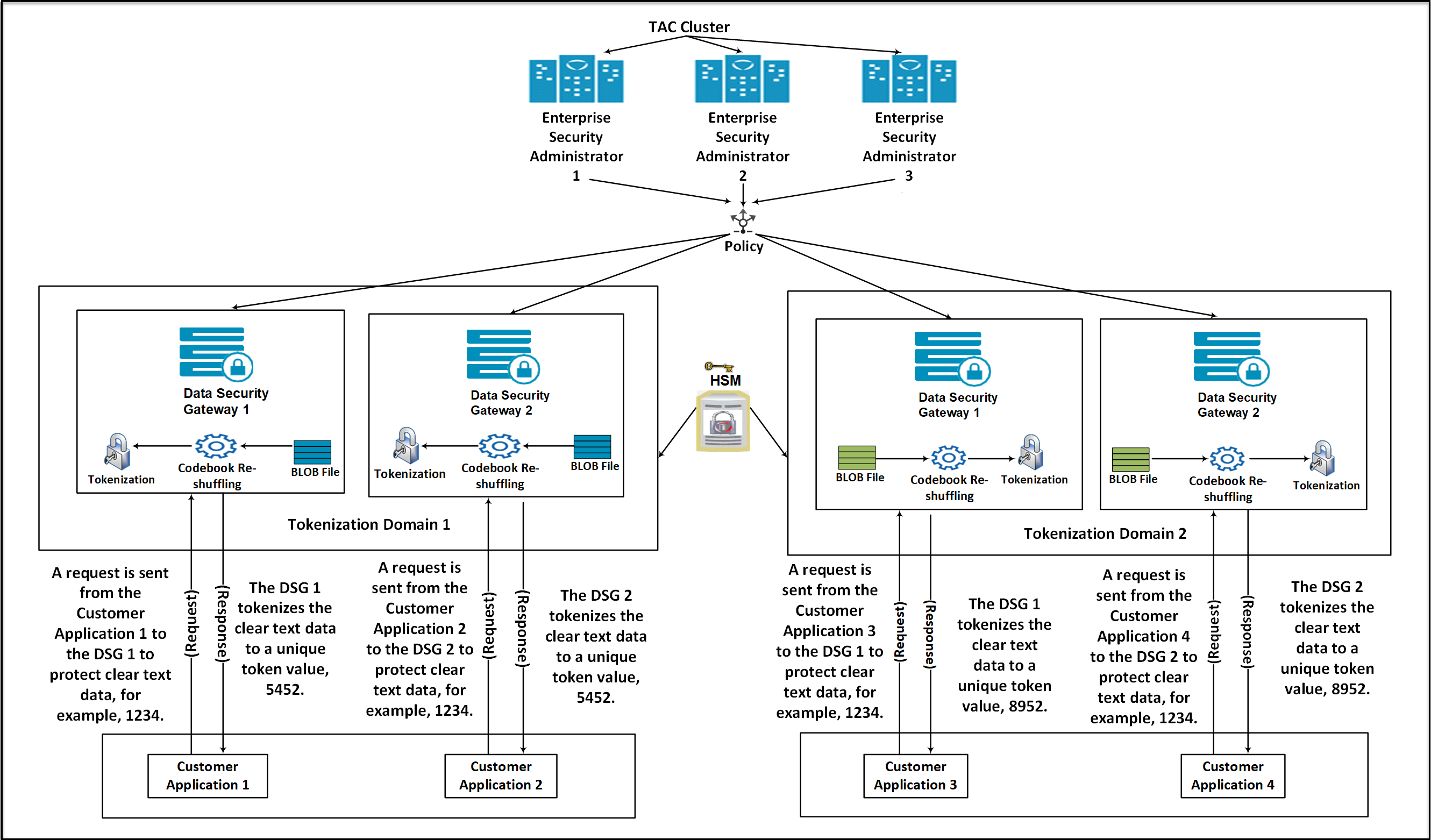
Consider a scenario where an organization has two tokenization domains, Tokenization Domain 1 and Tokenization Domain 2, which are distributed in two different tokenization domains. The Tokenization Domain 1 contains an ESA connected to multiple DSG nodes. A separate TAC for ESAs and DSGs is created.
On the ESA, create a tokenization data element. Codebooks are generated on the ESA when a tokenization data element is created.
Add the newly created tokenization data element to a policy.
Create a Binary Large Object (BLOB) file on each DSG node using the BLOB creation utility (BCU) that contains random bytes. The BLOB file will be encrypted automatically using an AES encryption key fetched from the HSM.
Deploy the policy created on the master ESA to the DSG nodes in Token Domain 1 and Token Domain 2. The DSG nodes download the policy information from the ESA. After the policy is deployed on the DSG, if the codebook reshuffling parameter is enabled, then the codebook will be shuffled again by using the BLOB file created on the DSG.
Create a Ruleset on the DSG nodes to protect the sensitive data.
After a request is sent from the client, the DSG processes and protects the sensitive data. It generates unique tokens for protected values across the tokenization domains.
The advantage offered by codebook reshuffling is that sensitive data on Token Domain 1 cannot be accessed by Token Domain 2. It cannot be accessed because it is protected by a different codebook, available only on the Token Domain 1. The unique tokens generated for the protected data on the Token Domain 1 can be used to derive an insightful analysis for an organization without compromising on any data security compliance and regulatory norms.
Codebook Reshuffling in the PEP Server
Codebook Reshuffling in the PEP server uses the BCU to create a Binary Large Object (BLOB) file that contains random bytes. The HSM encrypts these random bytes and sends it to the DSG. DSG saves these encrypted random bytes in a file. When the PEP server starts, it sends the encrypted random bytes to HSM for decryption. The HSM then decrypts the random bytes and sends it back to DSG. These random bytes are used by DSG to reshuffle the code books.
The file with random bytes is encrypted using an AES encryption key from the HSM and saved to the disk.
The PEP server loads the BLOB file from the disk and decrypts it using the key from the HSM. It then re-shuffles the supported codebooks, whenever a policy is published to shared memory. Based on the random bytes decrypted from the BLOB, codebook Reshuffling generates unique tokens for protected values across the tokenization domains.
Note: To configure the Codebook Reshuffling parameters in the pepserver.cfg file, contact Protegrity Support.
Ensure that you do not unprotect historically protected data using any token element as it causes data corruption if the shufflecodebooks parameter in the pepserver.cfg file is set to yes.
After the data is protected by enabling Codebook Reshuffling on the DSG, you must perform data security operations like protect, unprotect, and re-protect for the sensitive data by only using the Data Security Gateway (DSG) protector. Also, DSG does not support the migration of protected data, with the shufflecodebooks parameter in the pepserver.cfg file is set to yes, from the DSG to other protectors. An attempt to migrate the protected data and unprotecting it may cause data corruption.
The Codebook Reshuffling feature is tested and supported for the Safenet Luna 7.4 HSM devices. The procedure provided in this section is for the Safenet Luna 7.4 HSM devices.
To enable the reshuffling of codebooks in the PEP server:
Download the HSM library files. In this procedure, it is assumed that the HSM files are added to the /opt/protegrity/hsm directory.
Note: The HSM directory is not created on the DSG by default after DSG installation. Ensure that you use the following commands to create the HSM directory.
mkdir /opt/protegrity/hsmEnsure that the required ownership and permissions are set for the HSM library files in the /opt/protegrity/hsm directory by running the following commands.
chown -R service_admin:service_admin /opt/protegrity/hsm
chmod -R 744 /opt/protegrity/hsm
Ensure that the HSM library configuration files are available on the DSG.
Create a soft link to link the HSM shared library file using the following commands.
cd /opt/protegrity/defiance_dps/data
su -s /bin/sh service_admin -c "ln -s /opt/protegrity/hsm/<HSM shared library file> pkcs11.plm"
Create the environment settings file using the following commands.
echo "export <Variable Name>=<HSM Configuration file path> >> /opt/protegrity/defiance_
dps/bin/dps.env
chown service_admin:service_admin /opt/protegrity/defiance_dps/bin/dps.env
chmod 644 /opt/protegrity/defiance_dps/bin/dps.env
Export the HSM Configuration file parameter in the current session using the following command.
source ../bin/dps.envCreate the AES encryption key in the HSM using the following commands.
cd /opt/protegrity/defiance_dps/data
../bin/bcu -lib ./pkcs11.plm -op createkey -label <labelname> -slot <slotnumber> -userpin <SOME_USER_PIN>
Create a BLOB file using the BLOB creation utility (BCU), encrypt the BLOB file with the created encryption key, and save the BLOB file to the disk using the following command.
../bin/bcu -lib ./pkcs11.plm -op createblob -label <labelname> -slot <slotnumber> -size <size> -userpin <password> -file random.datCreate the credentials file for the PEP server to connect to the HSM using the following command.
../bin/bcu -op savepin -userpin <password> -file userpin.binEnsure that the required ownership and permissions are set for random.dat and userpin.bin files by using the following command.
chown service_admin:service_admin userpin.bin random.datCAUTION: Ensure that you backup the BLOB file and the user pin file and save it on your local machine. The BLOB file and the user pin files must not be saved on the DSG.
Ensure that you have set the shufflecodebooks configuration parameter to yes and the path to the file containing the random bytes in the pepserver.cfg configuration file using the following code snippet.
# shuffle token codebooks after they are downloaded.
# yes, no. default no.
shufflecodebooks = yes

# Path to the file that contains the random bytes for shuffling codebooks.
randomfile = ./random.dat
Note: The shufflecodebooks configuration parameter is available in the Policy Management section of the pepserver.cfg file.
Ensure that you have set the required path to the PKCS#11 provider library, slot number to be used on the HSM, and the required path to the userpin.bin file in the pepserver.cfg configuration file using the following code snippet.
# -----------------------------------
# PKCS#11 configuration
# Values in this section is only used
# when shufflecodebooks = yes
# -----------------------------------
[pkcs11]

# The path to the PKCS#11 provider library.
provider_library = ./pkcs11.plm

# The slot number to use on the HSM.
slot = 1 /Enter the slot number used at the time of the creation of the key/

# The scrambled user pin file.
userpin = ./userpin.bin
Note: The PKCS#11 configuration parameter is available in the PKCS#11 configuration section of the pepserver.cfg file.
Note: Ensure that the slot number added in step 8 of this procedure and the slot number added in step 12 are the same.
On the DSG Web UI, navigate to System > Services to restart the PEP server.
Re-protecting the Existing BLOB
This section describes the steps to reprotect the existing BLOB file with a new key. The user can encrypt the BLOB file by using the steps mentioned in the Codebook Reshuffling in the PEP Server section. These steps will allow the user to encrypt the BLOB using a key label of an AES key. After performing these operations, if the user wants to reprotect the BLOB with another key, then the user should create a new key and use the new key label to encrypt the BLOB. The reprotect operation provided will only reprotect the existing BLOB with a new key label and will not change the content in the BLOB.
To reprotect the existing BLOB:
Create the new AES encryption key in the HSM using the following commands.
./bcu -lib <safenet lib so file path> -slot <slotId> -userpin <userpin>
-op createkey -label <new_labelname>
Run the following command to reprotect the existing BLOB.
./bcu -lib <safenet lib so file path> -slot <slotId> -userpin <userpin>
-op reprotectblob -label <new_labelname> -file <blob filename>
Note: The BCU utility will not perform the reprotect operation of the BLOB, if the keys are used from different HSMs or from different slots or partitions.
Ensure that the required ownership and permission are set for the random.dat file by using the following commands.
chown service_admin:service_admin random.dat
chmod 640 random.dat
To have the changes made in the above steps reflected, login to the DSG Web UI and navigate to System > Services to restart the PEP server. You can view the success or failure logs of the reshuffling process on the PepServerLog screen on the DSG Web UI. To view the PepServerLog screen, navigate to Logs > PepServer.
On the PepServerLog screen, ensure that you have set the Log level to ALL in the pepserver.cfg file.
# ---------------------------------
# Logging configuration,
# Write application log to file as trace
# ---------------------------------
[logging]
# Logging level: OFF - No logging, SEVERE, WARNING, INFO, CONFIG, ALL
level = ALL
The following figure shows the PepServerLog after the BLOB file is encrypted with new key.
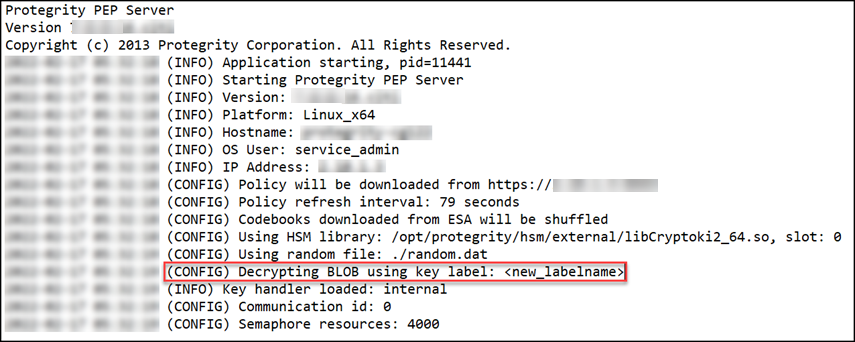
39.1 - Restore Backed up Files for Codebook Reshuffling
It is recommended to configure the HSM before restoring the backed up codebook re-shuffling configuration files.
The Codebook Re-shuffling feature is tested and supported for the Utimaco HSM and Safenet Luna 7.4 HSM devices. The procedure provided in this section is for the Utimaco HSM and Safenet Luna 7.4 HSM devices.
Login to the DSG Web UI.
On the DSG Web UI, navigate to Settings > System > File Upload.
Note: By default, the Max File Upload size is set to 25 MB on the DSG appliances. If the <filename>.tgz file size is more than 25 MB, the Max File Upload size must be changed. If this value is set to 2 GB, then the following steps can be ignored.
Perform the following steps to increase the Max File Upload size:
- On the DSG Web UI, navigate to Settings > Network > Web Settings.
- Under General Settings, ensure that the Max File Upload is set to 2 GB to accommodate the patch upload.
- Ensure that the steps 1 and 2 are performed on each DSG node in the cluster.
On the File Selection screen, select the <filename>.tgz file, which consists of the following backed up codebook re-shuffling files, and click Upload:
- BLOB (random.dat)
- dps.env
- User PIN (userpin.bin)
Login to the DSG CLI Manager.
Navigate to Administration > OS Console.
Enter the root password.
Navigate to the /products/uploads directory by running the following command.
cd /products/uploadsRun the following command to extract the contents of the <filename>.tgz file.
tar -xvpf <filename>.tgz -C /The contents of the <filename>.tgz file are extracted.
Setup the Token Domain for Codebook Re-shuffling by running the following commands.
cd /opt/protegrity/defiance_dps/data
su -s /bin/sh service_admin -c "ln -s /opt/protegrity/hsm/libCryptoki2_64.so pkcs11.plm"
Run the following command to source the dps.env file.
. /opt/protegrity/defiance_dps/bin/dps.envNote: The command has a dot followed by a space and then the path.
Ensure that you have set the shufflecodebooks configuration parameter to yes and the path to the file containing the random bytes in the pepserver.cfg configuration file using the following code snippet.
# shuffle token codebooks after they are downloaded.
# yes, no. default no.

shufflecodebooks = yes
# Path to the file that contains the random bytes for shuffling codebooks.
randomfile = ./random.dat
Ensure that you have set the required path to the PKCS#11 provider library, slot number to be used on the HSM, and the required path to the userpin.bin file in the pepserver.cfg configuration file using the following code snippet.
# -----------------------------------
# PKCS#11 configuration
# Values in this section is only used
# when shufflecodebooks = yes
# -----------------------------------
[pkcs11]

# The path to the PKCS#11 provider library.
provider_library = ./pkcs11.plm

# The slot number to use on the HSM.
slot = 1

# The scrambled user pin file.
userpin = ./userpin.bin
Note: The PKCS#11 configuration parameter is available in the PKCS#11 configuration section of the pepserver.cfg file.
On the DSG Web UI, navigate to System > Services to restart the PEP server.
The backed up Codebook Reshuffling configuration files are restored.
40 - Troubleshooting the DSG
TAC issues
Issue : Deleting registered DSG node from the ESA cluster screen (TAC) causes:
- ESA to point to the alternate DSG node.
- Secondary ESA will still reference the deleted DSG node, so node details won’t be visible.
Resolution: Run the ESA-ESA TAC replication job to restore cluster visibility.
For more information about TAC replication job, refer to the section TAC Replication Job.
Issue : If two different cluster operations are performed without any wait time, the changes may not be properly reflected in the ESAs and DSGs.
Resolution:
- Ensure a short interval between two distinct cluster operations for proper synchronization of changes.
- If changes are not properly synchronized, even after a short wait time, install the Consul service to resolve the issue. For more information about installing the Consul service, refer to the section Add/Remove Services.
DSG UI issues
DSG UI is not loading with an Internal Server error.
Issue: An Internal Server Error is displayed while accessing the DSG UI from ESA.
This issue occurs due to one of the following reasons:
- All the DSGs in the TAC are deleted
- The DSG node that is used to communicate with ESA is unhealthy. ESA then attempts to connect with another healthy node in the cluster. After multiple retries, if no healthy node with which ESA can communicate is found, this error is displayed on the screen.
Resolution:
- Run the ESA communication process on one DSG node.
For more information, refer to Setting up ESA communication. - Register the DSG node.
For more information, refer to Registering the DSG. - Add the DSG nodes to the cluster.
For more information, refer to Adding a DSG node
DSG UI is not loading with a certificate error.
Issue : The DSG UI does not load and a [SSL: TLSV1_ALERT_UNKNOWN_CA] entry is displayed in the logs.
This might occur as the certificates are not synchronized. The following are the few reasons for issue.
- ESA communication is not run.
- Resolution: The TAC is deleted and recreated.
- Resolution: If the TAC is deleted and recreated, run the set ESA communication process between the DSGs and ESA.
- If the set ESA communication is run, the certificates are synchronized multiple times.
- Resolution: Run the following steps:
- On the DSG UI, navigate to Cloud Gateway > {DSG Version} > Transport > Manage Certificates
- Click Change Certificates. A screen with the list of certificates is displayed.
- Based on the timestamp, select only the latest CA certficate from ESA.
- Unselect the other CA certificates from ESA. Ensure that you do not unselect other certificates in the list.
- Select Next. Click Apply.
- Resolution: Run the following steps:
DSG UI not loading with a NameResolutionError.
Issue : The DSG UI does not load and a NameResolutionError entry is displayed in the logs.
This might occur if the DSG or ESA are not accessible through their host names.
Resolution:
If DNS name server is not configured, ensure that FQDN of DSG is present in the /etc/hosts directory of ESA. Also, ensure that the FQDN of ESA is present in the /etc/hosts file of DSG.
For more information, refer to Update Host Details
DSG UI not loading as the DNS is not configured correctly.
Issue : The DSG UI does not load and a Failed to resolve 'protegrity-cg***.ec2.internal' ([Errno -2] Name or service not known)")) entry is displayed in the logs.
This might occur if the DSG or ESA are not accessible through their host names.
Resolution:
- Ensure that the DNS Name server is configured correctly.
DSG UI not loading with a certificate error.
Issue: An CERTIFICATE_VERIFY_FAILED error appears DSG appears in the logs.
This might occur if the DSG or ESA are not accessible through their host names. The issue can be mitigated as follows:
- Ensure that the DNS Name server is configured correctly.
- If DNS name server is not configured, ensure that FQDN of DSG is present in the /etc/hosts directory of ESA. Also, ensure that the FQDN of ESA is present in the /etc/hosts file of DSG.
For more information, refer to Update Host Details
DSG UI not loading with a KSA host error.
Issue: An error Failed to find new KSA host from the TAC is displayed in the logs.
The ESA reaches out to the DSG that is registered in the ksa.json file. If this DSG in not reachable, it attempts to connect with another healthy DSG in the cluster. If the attempt to connect with any healthy DSG node in the cluster fails, the issue occurs.
Resolution: Run the following steps:
- Check the health of all the nodes in the cluster.
- Check if the DSGs in the TAC are accessible.
- Check whether the set ESA communication between the DSG nodes and ESA was completed.
DSG UI not loading with a HTTP connection error
Issue: An error Request to X.X.X.X failed with error HTTPSConnectionPool(host='X.X.X.X', port=443): Max retries exceeded with url: /cpg/v1/ksa is displayed in the logs.
The ESA is not able to reach the DSG. Resolution: Run one of the following steps:
- Re-register the ESA with appropriate online DSG node
- Increase max retry count in the ksa.json file.
Unable to register DSG on ESA
Issue: An error Unable to add ptycluster user's SSH public key, Request failed due to 'Internal Server Error'. Please make sure host(protegrity-esa***.protegrity.com) have TAC enabled. is displayed in the logs.
Resolution: Ensure that the TAC is created on the DSG or ESA. Run the set ESA communication process for the DSG in the cluster.
Ruleset deployment
Rulesets are not deployed from ESA
Issue: When a ruleset is deployed from an ESA to DSG, the operation fails. A failure message is displayed in the logs.
This issue might occur due to one of the following reasons:
- One node in the TAC is deleted or unhealthy.
- TAC is deleted and recreated. Resolution: If the TAC is deleted and recreated, run the set ESA communication process again. Ensure that the certificates between ESA and DSG are synchronized.
Miscellaneous
Support logs are empty
Issue: When the support logs from a DSG Web UI are downloaded, the downloaded .tgz file is empty.
Resolution:
- On the ESA Web UI, ensure that the DSG Container UI service is up and running. If the service is stopped, restart the service. Download the support logs and check the entries.
- While installing a DSG patch on ESA, a details of the DSG node must be provided. Ensure that this DSG node is healthy. This DSG node must be accessible through its host name.
Other issues
Issue: An error
[SSL: TLSV1_ALERT_UNKNOWN_CA] tlsv1 alert unknown ca (_ssl.c:2546)is displayed in the logs.- Reason: Different CA certificates are present in the ESA nodes.
- Recovery Action: Ensure that all ESA nodes have the same CA certificates.
Issue: The following screen appears while installing the DSG.
Couldn't retrieve any matching DSG Host Address from xx.xx.xx.xx's server certificate
- ip-xx-xx-xx-xx.ec2.internal [absent from server certificate]
- protegrity-esaxxx.ec2.internal [absent from server certificate]
- protegrity-esaxxx [absent from server certificate]
- xx.xx.xx.xx [absent from server certificate]
Reason: The IP Address, Host Name, or FQDN is not found in the CA or SAN field of the CA certicate.
Recovery Action: Generate new certificates and check if the IP Address, Host Name, or FQDN is present in the CA certificate.
Issue: An error
HTTP Error 596: source is not whitelistedis displayed on the ESA container logs.- Reason: The issue occurs if the Update Host Settings for DSG step is not completed while performing ESA communication.
- Recovery Action:
Ensure the Update Host Settings for DSG step is selected when performing ESA communication.
For more information about ESA Communication, refer to Setting up ESA communication.
Issue: The usage metrics are not forwarded to Insight.
- Reason: The /var/log partition is full.
- Recovery Action:
Perform the following steps.
- Back up the gateway.log files.
- Ensure that the partition space is cleared. To free up the space, you can remove the rotated gateway log files.
- Delete or purge the *usagemetrics.pos* file from the */opt/protegrity/usagemetrics/bin directory*.
- On the Web UI, navigate to System > Services. Restart the **Usage Metrics Parser Service**.
Issue: When SaaS is accessed through the gateway, the following error is displayed.
HTTP Response Code 599: Unknown.- Reason 1: The SaaS server certificate is invalid.
- Recovery Action:
Perform one of the following steps.
- Ensure that the forwarding address is correct.
- Add the SaaS server certificate to the gateway’s trusted store.
- Reason 2: The system time on the DSG nodes is not in sync with the ESA.
- Synchronize the system time for all the DSG nodes performing the following steps.
- From the CLI Manager, navigate to Tools > ESA communication.
- Select **Use ESA’s NTP** to synchronize the system time of the node with ESA.
- Consider using an NTP server for system time across all DSG nodes and the ESA.
- Synchronize the system time for all the DSG nodes performing the following steps.
- Reason 3: The DNS configuration might be incorrect.
- Recovery Action:
Perform one of the following steps.
- Verify that the DNS configuration for the DSG node is set as required.
- Verify that the hostname addresses mentioned in the service configuration are accessible by the DSG node.
Issue: The SaaS web interface is not accessible through the browser. Following error is displayed.
HTTP Response Code 500: Internal Server Error.- Reason: The DSG node is not configured to service the requested host name.
- Recovery Action: Verify if the Cloud Gateway profiles and services are configured to accept and serve the requested hostname.
Issue: The following error message appears on the client application while accessing DSG.
404 : Not Found- Reason: The HTTP Extract Message rule configured on the DSG node cannot be invoked.
- Recovery Action:
Perform one of the following steps.
- Ensure that you have sent the request to the URI configured on the DSG. If the request is sent to the incorrect URI, then the request will not be processed.
- Verify the HTTP Method in the HTTP request.
Issue: The following error message appears in the gateway logs
Error;MountCIFSTunnel;check_for_new_files;error checking for new files, Connection timed out. Server did not respond within timeout.- Reason: The connection between the DSG and CIFS server is interrupted.
- Recovery Action: Restart the CIFS server and process the data.
Issue: Learn mode is not working.
- Reason: Learn mode is not enabled.
- Recovery action: Perform one of the following steps.
- Enable learn mode for the required service.
- Configure the following learn mode settings while creating the service.
- Mention the contents to be included in the *includeResource* and the *includeContentType* parameters.
For example, you can include the following resources and content types:"includeResource": "\\.(css|png|gif|jpg|ico|woff|ttf|svg|eot)(\\?|\\b)","includeContentType": "\\bcss|image|video|svg\\b", - Mention the contentsto be excluded in the *excludeResource* and the *excludeContentType*parameters.
For example, you can excludethe following resources and content types:"excludeResource": "\\.(css|png|gif|jpg|ico|woff|ttf|svg|eot)(\\?|\\b)","excludeContentType": "\\bcss|image|video|svg\\b",
- Mention the contents to be included in the *includeResource* and the *includeContentType* parameters.
Issue: Following message is displayed in the log
WarningPolicy;missing_host_key;Unknownssh-rsa host key for:f1b2e0bde5d34244ba104bab1ce66f96 - Reason: The gateway issues an outbound request to an SFTP server.
- Recovery action: The functionality of the DSG node is not affected. No action is required.
Set ESA communication is failing
Issue: While running the set ESA communication tool, the process fails. The following can one of the reasons for the failure:
- PIM initialization is not done on ESA. Workaround: Initialize the PIM on the ESA.
- A TAC is not created on DSG. Workaround: Create a cluster on a DSG and add the required nodes to the cluster.